BCM MX680RD User's Quick Start Card
Intel r680e pch
Hide thumbs
Also See for MX680RD:
- User manual (83 pages) ,
- User's quick start card (8 pages) ,
- User manual (121 pages)
Advertisement
Quick Links
MX680RD (71876)
Intel® R680E PCH
Supports LGA1700 Alder Lake-S
& Raptor Lake-S (13
Core™ i9, Core i7, Core i5, Core i3, Pentium, Celeron
(65W TDP
max) with DDR5-4800 SODIMM
Mini-ITX Motherboard
User's Quick Start Card
• Inspect the Package:
• Responsibility:
This manual is provided "As-Is" with no warranties of any kind, it will neither expressed or implied,
including, but not limited to the implied warranties or conditions of this product's fitness for any
particular purpose. In no event shall we be liable for any loss of profits, loss of business, loss of data,
interruption of business, or indirect, special, incidental, or consequential damages of any kind, even
the possibility of such damages arising from any defect or error in this manual or product. We reserve
the right to modify and update the user manual without prior notice.
WARNING: CMOS Battery Damage
Replace your system's CMOS RAM battery only with the identical CR-2032 3V Lithium-Ion coin cell
(or equivalent) battery type to avoid risk of personal injury or physical damage to your equipment.
Always dispose of used batteries according to the manufacturer's instructions, or as required by the
local ordinance (where applicable). The damage due to not following this warning will void your
motherboard's manufacturer warranty.
Perchlorate Material- Special Handling May Apply.
See
http://www.dtsc.ca.gov/hazardouswaste/perchlorate/
th
(12
Gen)
th
Gen,
BCM P/N# 71876
ONLY)
http://www.bcmcom.com
Version 1.02
ATTENTION: Incorrect BIOS Setup
If you do not know how to handle BIOS setup or how to set it up properly, it is strongly advisable that
you do not modify any of the settings than otherwise instructed in the User's Quick Start Card. Even
a seemingly small incorrect adjustment or modification in the BIOS setup can render your system
unstable or unusable. The incorrect BIOS setup is not covered by your motherboard's manufacturer
warranty.
• Additional Information:
Additional information on setting this board up can be found in the User's Manual from BCM website.
The
Online
User's Manual
can
be found
http://www.bcmcom.com. If your question is not answered in our FAQ/Knowledge Base, visit our
forums and post your messages or submit a new FAQ through FAQ Submittal form for us to add your
question in our FAQ with our answer.
WARNING: Electrostatic Sensitive Device (ESD)
Static electricity can easily damage your motherboard and will void your motherboard warranty. Keep
the motherboard and other system components in their anti-static packaging until you are ready to
install them. Touch a grounded surface before you remove any system component from its protective
anti-static packaging. Unpacking and installation should be done on a grounded, anti-static mat. The
operator should be wearing an anti-static wristband, grounded at the same points as the anti-static
mat. During configuration and installation touch a grounded surface frequently to discharge any static
electrical charge that may have built up in your body. Avoid touching the components when handling
the motherboard or a peripheral card. Handle the motherboard and peripheral cards either by the
edges or by the peripheral card case-mounting bracket.
WARNING: Misplaced Jumper Damage
Incorrect setting jumpers and connectors may lead to damage to your motherboard and will void your
motherboard warranty.
Please pay special attention not to connect these headers in wrong
directions. DO NOT change ANY jumpers while the motherboard has the power!
on
our
website
by
visiting
our
website:
Advertisement

Subscribe to Our Youtube Channel
Related Manuals for BCM MX680RD


Summary of Contents for BCM MX680RD
- Page 1 Core™ i9, Core i7, Core i5, Core i3, Pentium, Celeron warranty. (65W TDP max) with DDR5-4800 SODIMM Mini-ITX Motherboard • Additional Information: Additional information on setting this board up can be found in the User’s Manual from BCM website. User’s Quick Start Card http://www.bcmcom.com Version 1.02 Online User’s Manual...
-
Page 2: Application Note
3. Clear CMOS when a different model of CPU is installed: ii. Under “Security Device Support”, change it to “Enable”. If a different model of CPU is being installed with the same MX680RD board, it is recommended to c. Under “Save & Exit” option, choose “Save Changes and Exit”. - Page 3 1. In order to install the optional Realtek Audo Control Console, user needs to install the provided k. Insert USB keys that contains the Win10 installation files and BCM provided driver “MS Visual C++ 2015 (14.0.30704.0) first (by double click on the appx file to install).
-
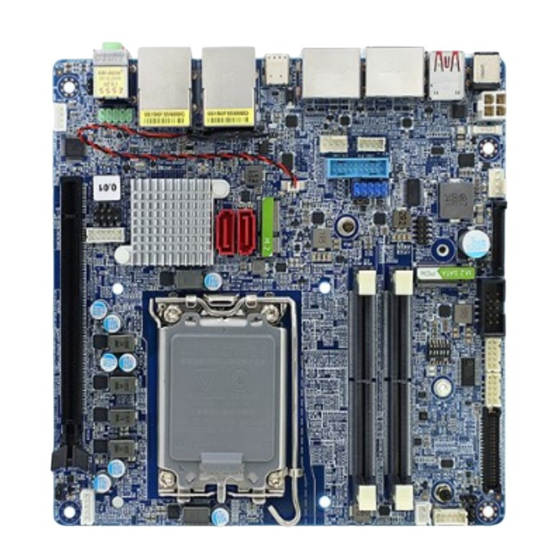
Page 4: Motherboard Layout
Motherboard Layout: Click on “Browse”, then point to the directory where the BCM provided driver “(OPTIONAL) • Board Layout: RST_19.2.0.1003”->”F6 (browse during Win installation)”->”VMD”->”f6vmdflpy-x64”, then click on (Top Side) “OK”. o. Click on the option “Intel RST VMD Controller 467F”, then click on “Next” to proceed. - Page 5 (Bottom Side) • Back Panel (Rear IO): Item Name Function Description DC_IN DC-in connector The connector is for DC-in (12V~24V) (19V recommended, 8A max) DC Mate Plug: DIA. 5.5mm (Outer) x 2.5mm (Inner). USB3_P910 USB 3.2 These two Universal Serial Bus (USB) ports are Connectors available for connecting USB 3.2 devices.
- Page 6 (Use only either the “DC-IN” connector at rear I/O, or this connector for Network (LAN) through a network hub. Refer to the (RJ-45) power connection of MX680RD). table below for the LAN port LED indications. Connectors ACT/Link LED Speed LED...
-
Page 7: Atx/At Mode Selection: Jpson1
• ATX/AT Mode Selection: JPSON1 • Fan Connectors: SYS_FAN1 • Front Panel Connector: F_PANEL1 • Serial Port Connectors: COM1, COM2 • Fan Connectors: CPU_FAN1 • COM Mode Setting for COM1, COM2: RI_SEL1... - Page 8 • M.2 Connectors: M2E1, M2E1, M2M2 • SATA 3.0 Ports: SATA1, SATA2 Top Side: • Front USB 3.2 Headers: USB3_P56 Bottom Side: Item Description Note • Front USB 2.0 Headers: USB1112 M2E1 M.2 Key-E Slot (2230) Supports PCIe x1, USB2.0, CNVi M2M1 M.2 Key-M Slot (2242/ 2280)
- Page 9 • LVDS panel connector: LVDS1 • LVDS Brightness Control Mode Selection: JLVDS_BKL1 • Front Panel Audio Connector: FP_AUDIO1 • LVDS panel backlight connector: JBKL1 • Audio Amplifier Connector: JAMP1 • LVDS Panel Voltage Selection: JBKLVOL1...
- Page 10 • Digital I/O (GPIO) Header: JDIO1 • Chassis Intrusion Connector: JCASE1 • SMBus Header: SMBUS1 • Save the Processor Socket Cover After removing the processor cover during processor installation, please save the processor socket cover. In the event that the desktop board needs to be returned for service or any time the processor is removed, the cover should be placed on the processor socket.
Need help?
Do you have a question about the MX680RD and is the answer not in the manual?
Questions and answers