
Related Manuals for Aydin Displays LCD Monitor

Summary of Contents for Aydin Displays LCD Monitor
-
Page 1: Users Manual
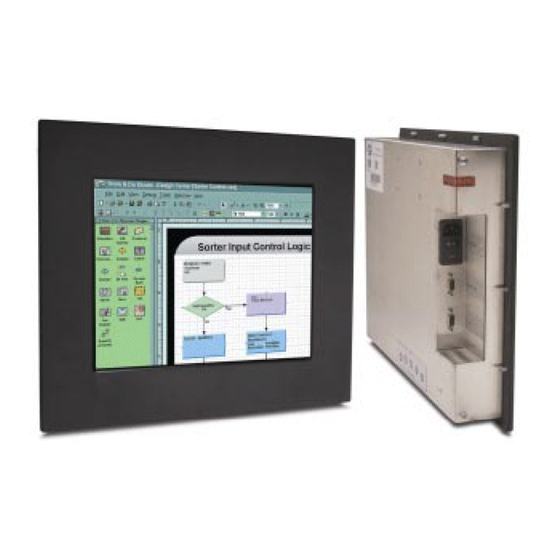
CAMBRIDGE USERS MANUAL CFP19 Family Panel Mount Rack Mount VESA Wall Mount LCD Monitor User Guide 150-CFP-190(-) -
Page 2: Table Of Contents
Contents Section 1 Display Set-up....................... 3 Product Safety Precautions ....................3 Included Parts ........................3 Connecting Your Display ....................4 Section 2 Getting Started......................5 Display Features ......................... 5 Adjusting the Display ......................5 Keyboard Layout & Functions ................... 5 Section 3 Touch Screen Set-up.................... -
Page 3: Section 1 Display Set-Up
Do not expose the display to direct sunlight or heat. Included Parts Open shipping container and lay all components on a flat clean surface. Your LCD monitor package will consist of the primary components listed below: • LCD Monitor •... -
Page 4: Connecting Your Display
LCD monitor. If this happens, you will need to adjust the computer to output a compatible video signal (see Appendix G). -
Page 5: Section 2 Getting Started
Getting Started Section Display Features • The LCD is capable of displaying 16.7M colors in a continuous spectrum. • The high contrast LCD enhances the image with no geometric distortion. • The LCD directly accepts an Analog 3, 4 or 5 Wire RGB with sync input. •... - Page 6 5. Push the Menu button a couple of times to return to the Main Menu to slect another function or to exit from the OSD. 150-CFP-190(-)
- Page 7 150-CFP-190(-)
- Page 8 150-CFP-190(-)
- Page 9 150-CFP-190(-)
-
Page 10: Section 3 Touch Screen Set-Up
Touch Screen Set-up Section Introduction to Touch Screens Touch screen interfaces have become the standard interface in the past 5 years. They are rugged, reliable, extremely flexible and easier than ever to implement! The universal acceptance of the Windows GUI (Graphical User Interface) along with the extensive use of a mouse interface has significantly accelerated the use of a touch interface. -
Page 11: Section 4 Mounting Instructions
Mounting Instructions Section Panel Mounting Procedure 1. Cut and drill the panel to the proper size (see panel cutout in Appendix H). Measurements are shown in inches. 2. If access to the side of monitor is not available following installation, attach the power and video cables to the side of the monitor at this time. -
Page 12: Section 5 Touble Shooting Tips
Image persistence occurs when a ghost of an image remains on the screen after the screen image has been changed. Unlike a CRT monitor, an LCD monitor’s image persistence is not permanent. To erase an image ghost, turn the monitor off for several hours. - Page 13 Display image is not Press the “Select” button to Auto Adjust the display. properly sized Adjust the Vertical and Horizontal size controls via the OSD (reference OSD Adjustments). Ensure that a supported mode is selected on the display card or system being used. Consult the display card or system manual for proper video.
-
Page 14: Section 6 Cleaning And Maintenance
Cleaning & Maintenance Section Cleaning Occasionally clean the display panel and cabinet with a soft cloth dampened (not soaked) with a mild (non-abrasive) glass cleaner. Keep turning a fresh side of the cloth toward the screen surface to avoid scratching it with accumulated grit. NOTE: The solvent should be applied only to the cloth, NOT directly on the monitor screen. -
Page 15: Section 7 Appendices
Appendices Section Appendix A – Video Pin Assignments Pin assignments for the HD15 Video Connector Pin 1 Red Video Pin 9 No Connection Pin 2 Green Video Pin 10 Sync Ground Pin 3 Blue Video Pin 11 Not Used Pin 4 Not Used Pin 12 Bi-Directional Data... -
Page 16: Appendix C - Dvi Video Pin Assignments
Appendix C – DVI Video Pin Assignments Pin 1 TMDS Data 2- Pin 2 TMDS Data 2+ Pin 3 TMDS Data 2/4 Shield Pin 4 TMDS Data 4- (NC) Pin 5 TMDS Data 4+ (NC) Pin 6 DDC Clock Pin 7 DDC Data Pin 8 No Connection... -
Page 17: Appendix F - General Specifications
Appendix F – CFP19 Specifications Active Screen Area 14.82” x 11.85” (376.32 x 301.056mm) Pixel Pitch .294mm Response Time 15/10ms typical Brightness 250 nits typical Contrast 600:1 Lamp Life Wide Dimming Range Optional Max Screen Resolution VGA/SXGA PC Video Input Separate Sync (5 Wire) Composite Sync (4 Wire) Sync on Green (3 Wire) -
Page 18: Appendix G - Supported Video Modes
Appendix G – Supported Video Modes Mode Resolution Clk [MHz] Horizontal freq Vertical freq Sync Mode [KHz] [Hz] E1_70 640x350 25.175 31.469 Digital Separate Sync E1_70 640x350 25.175 31.469 Sync On Green (with or without serrate pulse) E1_70 640x350 25.175 31.469 Composite Sync (with or without serrate pulse) E1_85... - Page 19 X_60 1024x768 65.000 48.363 Digital Separate Sync X_60 1024x768 65.000 48.363 Sync On Green (with or without serrate pulse) X_60 1024x768 65.000 48.363 Composite Sync (with or without serrate pulse) X_70 1024x768 75.000 56.476 Digital Separate Sync X_70 1024x768 75.000 56.476 Sync On Green (with or without serrate pulse) X_70...
-
Page 20: Appendix H - Mounting Dimensions
Appendix H – Mounting Dimensions CFP19P1 Outline Dimensions 150-CFP-190(-) - Page 21 Appendix H – Mounting Dimensions CFP19P1 Cutout Dimensions 150-CFP-190(-)
- Page 22 Appendix H – Mounting Dimensions CFP19R1 Rack Mount 150-CFP-190(-)
- Page 23 Appendix H – Mounting Dimensions CFP19W1 Wall Mount 150-CFP-190(-)
Need help?
Do you have a question about the LCD Monitor and is the answer not in the manual?
Questions and answers