
Subscribe to Our Youtube Channel
Related Manuals for Gefen GTV-VOLCONT-DA


Summary of Contents for Gefen GTV-VOLCONT-DA
- Page 1 2.1 Audio Amplifi er w/ Volume Stabilizer GTV-VOLCONT-DA User Manual www.gefentv.com...
- Page 3 Notice Gefen LLC reserves the right to make changes in the hard ware, packaging and any accompanying doc u men ta tion without prior written notice. For the latest fi rmware updates for this product, please visit Gefen’s download Web page at http://www.gefen.com/kvm/support/download.jsp...
-
Page 4: Table Of Contents
CONTENTS Introduction Operation Notes Features Front Panel Layout Front Panel Descriptions Back Panel Layout Back Panel Descriptions IR Remote Control Layout and Descriptions Installing the Battery Setting the IR Channel 11 Connection the 2.1 Audio Amplifi er w/ Volume Stabilizer Wiring Diagram 12 Operating the 2.1 Audio Amplifi... -
Page 5: Introduction
INTRODUCTION Congratulations on your purchase of the GefenTV 2.1 Audio Amplifi er w/ Volume Stabilizer. Your complete satisfaction is very important to us. GefenTV GefenTV is a unique product line catering to the growing needs for innovative home theater solutions. We specialize in total integration for your home theater, while also focusing on going above and beyond customer expectations to ensure you get the most from your hardware. -
Page 6: Operation Notes
OPERATION NOTES READ THESE NOTES BEFORE INSTALLING OR OPERATING THE GEFENTV2.1 AUDIO AMPLIFIER W/ VOLUME STABILIZER • GefenTV 2.1 Audio Amplifi er w/ Volume Stabilizer will use psycho- acoustic technology to adjust volume automatically. It is best used for TV programming where the level of sound rises and falls to an unacceptable level. -
Page 7: Features
FEATURES Dolby® Volume features: • Volume Leveler: Enables consistent volume levels at all times between TV channels and between program materials • Volume Modeler: Delivers the perception of a full-range audio experience at any volume level • Audio settings can be customized to suit your personal preferences and listening conditions. -
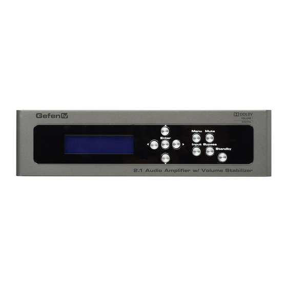
Page 8: Front Panel Layout
FRONT PANEL LAYOUT... -
Page 9: Front Panel Descriptions
FRONT PANEL DESCRIPTIONS Main LCD Display This display will show pertinent status information and will be used to make adjustments to features in the Menu System. Left Cursor Button This button is used to navigate the Menu System and change settings by moving the cursor to the left. -
Page 10: Back Panel Layout
BACK PANEL LAYOUT... -
Page 11: Back Panel Descriptions
BACK PANEL DESCRIPTIONS RS-232 Serial Port This port is used for serial communication using an RS-232 control device. Access to certain features are only available through the RS-232 interface. Analog L/R (RCA) Input Connect an RCA L/R stereo pair from the source to these two ports. Optical (TOSLINK) Input Connect an Optical cable from the source to this port. -
Page 12: Ir Remote Control
IR REMOTE CONTROL Layout and Descriptions Activity Indicator This LED will be activated momentarily each time a button is pressed. Power Off Turns off the unit. Power On Switches to the optical (TOSLINK) audio input. Bypass On Disables Dolby Volume control. Bypass Off Enables Dolby Volume control. - Page 13 IR REMOTE CONTROL Menu Places the unit in Menu Mode, allowing access to all menu systems. Optical Switches to the optical (TOSLINK) audio input. Coax Switches to the coax (S/PDIF) audio input. 10 L/R Switches to the analog L/R RCA audio input. 11 Mute Off Disables the volume muting.
-
Page 14: Installing The Battery
IR REMOTE CONTROL Installing the Battery The Remote Control unit ships with two batteries. One battery is required for operation and the other battery is a spare. Remove the battery cover on the back of the IR Remote Control unit. Insert the included battery into the open battery slot. -
Page 15: Wiring Diagram
Wiring Diagram for the 2.1 Audio Amplifi er w/ Volume Stabilizer DIGITAL (TOSLINK) AUDIO CABLE DIGITAL (COAX) AUDIO CABLE Audio Source ® ANALOG (RCA) AUDIO CABLE SUBWOOFER (RCA) AUDIO CABLE SPEAKER CABLE Audio Source RS-232 CABLE Audio Source GefenTV 2.1 Audio Amplifier w/Volume Stabilizer Speaker Speaker Subwoofer RS-232 Controller GTV-VOLCONT-DA... -
Page 16: Status Screen
OPERATING THE 2.1 AUDIO AMPLIFER W/ VOLUME STABILIZER Status Screen The Status Screen displays information regarding the current settings of the Volume Stabilizer The Status Screen is also used in conjunction with navigating the built-in Menu System. After powering on the Volume Stabilizer, the Standby Screen will be displayed. The Standby Screen indicates the currently selected A/V input, the current volume setting, the audio input format, and the audio processing mode: Audio Input... -
Page 17: Selecting The Audio Input
OPERATING THE 2.1 AUDIO AMPLIFER W/ VOLUME STABILIZER Selecting the Audio Input Use the Input Button to select between Coax (S/PDIF) or Optical (TOSLINK) inputs. Each time the Input Button is pressed, the Audio Amplifi er will cycle to the next input option. The currently selected audio input will be displayed in the Status Screen: ... -
Page 18: Bypass Mode
OPERATING THE 2.1 AUDIO AMPLIFER W/ VOLUME STABILIZER Bypass Mode Bypass mode is recommended when listening to music or watching movies which have a wide dynamic range. When Bypass mode is enabled, Dolby® Volume processing is disabled. Bypass mode can be enabled or disabled by using the Bypass button on the front panel. -
Page 19: Menu System
MENU SYSTEM Using the Menu System The 2.1 Audio Amplifi er w/ Volume Stabilizer comes with a built-in menu system which provides control over additional audio features. The following examples demonstrate some of the more common features of the Volume Stabilizer. Setting the Speaker Size Adjusting the speaker size determines how each speaker handles low frequency bands. - Page 20 MENU SYSTEM Subwoofer Crossover Frequency If the speaker size for Sub is set to OnSub, then the subwoofer crossover frequency can be adjusted. Speaker Crossover Frequency 50 Hz 60 Hz 90 Hz Press the ▼ button. The following screen will be displayed: ...
-
Page 21: Setting The Speaker Level
MENU SYSTEM Setting the Speaker Level Modifying the Speaker Level increases or decreases the audio output gain of a specifi c speaker. This feature is useful for equalizing the sound at the listening position. By default, each speaker’s output is set to 0 dB. The output can be adjusted by 1 dB increments between -10 dB and +10 dB. - Page 22 MENU SYSTEM Front Right Press the ▼ button. The following screen will be displayed: Use the ◄ and ► buttons on the front panel to adjust the speaker gain. Subwoofer Press the ▼ button on the front panel. The following screen will be displayed: ...
-
Page 23: Adjusting The Speaker Distance
MENU SYSTEM Adjusting the Speaker Distance Adjusting the speaker adds delay in the audio signal which allows the speaker to sound as if it is a certain distance away even when there is no space to physically position it father away from the listener. A 1ms delay is equivalent to moving the speaker away (from the listener) by 1 foot. -
Page 24: Adjusting The Tone Control
MENU SYSTEM Subwoofer Press the ▼ button. The following screen will be displayed: Use the ◄ and ► buttons on the front panel to adjust the speaker distance for the Subwoofer. Exiting the Speaker Distance Menu Press the ▼ button. The following screen will be displayed: ... - Page 25 MENU SYSTEM Press the Enter button. Use the ◄ and ► buttons on the front panel to adjust the amount of bass (low frequency boost) applied to the output audio signal: Treble Press the ▼ button. The following screen will be displayed: ...
-
Page 26: Miscellaneous Setup
MENU SYSTEM Miscellaneous Setup The Miscellaneous Setup Menu (Misc. Setup) provides controls for enabling or disabling Dolby® Volume, adjusting the Dolby® Volume threshold, down-mixing, line-out mode, IR channel, front-panel contrast setting, and output impedance. Miscellaneous Setup Menu Bypass 2CH Downmix Dolby Volume Level Lt/Rt Lo/Ro... - Page 27 MENU SYSTEM 2 Channel Downmix Press the ▼ button on the front panel to display the 2 Channel Downmix screen: Use the ◄ and ► buttons on the front panel to between Lo / Ro and Lt / Rt. If the downmix is set to Lo / Ro, then only the Left and Right channels will be mixed down to 2 channel stereo.
- Page 28 MENU SYSTEM FIX: Set the Line Out Mode to FIX if the volume will be controlled by an external amplifier. AMP: Set the Line Out Mode to AMP if the volume will be controlled by the GefenTV 2.1 Audio Amplifier w/ Volume Stabilizer. IR Channel From the Line Out Mode screen, press the ▼...
- Page 29 MENU SYSTEM Impedance Press the ▼ button. The following screen will be displayed: Use the ◄ and ► buttons on the front panel to change the impedance value. Exiting the Tone Control Menu Press the ▼ button. The following screen will be displayed: ...
-
Page 30: Rs-232 Serial Control
RS-232 SERIAL CONTROL 5 4 3 2 1 1 2 3 4 5 9 8 7 6 6 7 8 9 Only Pins 2 (RX), 3 (TX), and 5 (Ground) are used on the RS-232 serial interface RS-232 Settings Bits per second .................... 19200 Data bits ....................... - Page 31 RS-232 COMMANDS Commands Command Description 2-channel downmixing 2chmx Increases / decreases the amount of bass bass Reset unit to factory (default) settings dfl t Sets the distance for the Front Left speaker distfl Sets the distance for the Front Right speaker distfr Sets the distance for the Subwoofer distsb...
- Page 32 RS-232 COMMANDS 2CHMX Command The 2CHMX command down-mixes the output signal to two channels. Syntax 2chmx param1 Parameters: Value param1 Value Meaning LoRo Downmix LoRo LtRt Downmix Lt/Rt Notes: Use ? for param1 to retrieve the current value. Examples 2chmx ltrt >...
- Page 33 RS-232 COMMANDS BASS Command The BASS command sets the bass level. Syntax bass param1 Parameters: Level [-12 ...12] param1 Notes: The + or - character can also be used, instead of specifying a value, in order to increase or decrease the bass level by 1 dB. Use ? for param1 to retrieve the current value.
- Page 34 RS-232 COMMANDS DFLT Command The DFLT command sets the unit to the default settings. Syntax dfl t Parameters: None Example: dfl t > DEFAULT...
- Page 35 RS-232 COMMANDS DISTFL Command The DISTFL command sets the distance (in feet) for the Front Left speaker. Syntax distfl param1 Parameters: Distance [0 ... 33] param1 Notes: The + or - character can also be used, instead of specifying a value, in order to increase or decrease the distance by 1 foot intervals.
- Page 36 RS-232 COMMANDS DISTFR Command The DISTFR command sets the distance (in feet) for the Front Right speaker. Syntax distfr param1 Parameters: Distance [0 ... 33] param1 Notes: The + or - character can also be used, instead of specifying a value, in order to increase or decrease the distance by 1 foot intervals.
- Page 37 RS-232 COMMANDS DISTSB Command The DISTFB command sets the distance (in feet) for the Subwoofer. Syntax distsb param1 Parameters: Distance [0 ... 33] param1 Notes: The + or - character can also be used, instead of specifying a value, in order to increase or decrease the distance by 1 foot intervals.
- Page 38 RS-232 COMMANDS DV Command The DV command enables or disables the Dolby® Volume control. Syntax dv param1 Parameters: Value [ON, OFF] param1 Value Meaning Dolby® Volume On (Bypass Off) Dolby® Volume Off (Bypass On) Notes: Use ? for param1 to retrieve the current value. When using a ? for param1, do not include a space between the command and the parameter.
- Page 39 RS-232 COMMANDS DVL Command The DVL command sets the Dolby® Volume level. Syntax dvl param1 Parameters: Value param1 Value Meaning Dolby® Volume Low Dolby® Volume Med HIGH Dolby® Volume High Notes: Use ? for param1 to retrieve the current value. When using a ? for param1, do not include a space between the command and the parameter.
- Page 40 RS-232 COMMANDS FLR Command The FLR command sets the size for the Front Left / Front Right speakers. Syntax fl r param1 Parameters: Size [0 ... 1] param1 Value Meaning Small Front Speakers Large Front Speakers Notes: Use ? for param1 to retrieve the current value. When using a ? for param1, do not include a space between the command and the parameter.
- Page 41 RS-232 COMMANDS INFO Command The INFO command returns hardware and fi rmware version. The ? character must follow the command without a space. Syntax info? Parameters: param1 Example info? > FM 2.21 - HW 2.05 INPUT Command The INPUT command selects the audio input. Syntax input param1 Parameters:...
- Page 42 RS-232 COMMANDS INTYPE Command The INTYPE query command returns the audio input format. Syntax intype Parameters: None Notes: Depending upon the audio input format, the INTYPE command will return one of the following values: Value Meaning PCM 2CH PCM Stereo DOLBY 2CH Dolby Digital 2.1 DOLBY 5.1...
- Page 43 RS-232 COMMANDS IR Command The IR command sets the IR channel. Syntax IR param1 Parameters: Channel [1 ... 4] param1 Input Meaning IR Channel 1 IR Channel 2 IR Channel 3 IR Channel 4 Notes: Use ? for param1 to retrieve the current value. When using a ? for param1, do not include a space between the command and the parameter.
- Page 44 RS-232 COMMANDS LCMCNTRST Command The LCMCNTRST command sets the contrast level for the front panel LCD. Syntax > lcmcntrst param1 Parameters: Value param1 Value Meaning Increase brightness level by 1 Decrease brightness level by 1 Examples: lcmcntrst + > LCMCNTRST 3 lcmcntrst - >...
- Page 45 RS-232 COMMANDS LFV Command The LFV command sets the output gain of the Left Channel. Syntax lfv param1 Parameters: Value param1 Value Meaning Increase gain by 1 dB Decrease gain by 1 dB Notes: Use ? for param1 to retrieve the current value. When using a ? for param1, do not include a space between the command and the parameter.
- Page 46 RS-232 COMMANDS LINEOUT Command The LINEOUT command sets the audio output mode. When LINEOUT mode is set to FIX, then the external amplifi er is used to control the main output volume. When LINEOUT mode is set to AMP, then the 2.1 Audio Amplifer w/ Volume Stabilizer controls the main audio output volume.
- Page 47 RS-232 COMMANDS MUTE Command The MUTE command sets the audio mode. Syntax mute param1 Parameters: Mode param1 Mode Meaning Disable mute Enable mute TOGGLE Mute toggle Notes: Use ? for param1 to retrieve the current value. When using a ? for param1, do not include a space between the command and the parameter.
- Page 48 RS-232 COMMANDS POWER Command The POWER command turns the unit ON or OFF. Syntax power param1 Parameters: Mode param1 Mode Meaning Power save mode Power On TOGGLE Toggle the power state Notes: Use ? for param1 to retrieve the current value. When using a ? for param1, do not include a space between the command and the parameter.
- Page 49 RS-232 COMMANDS RST Command The RST command resets the unit. Syntax Parameters: None Example: > RESET Notes: The RST command cannot be used when the 2.1 Audio Amplifer w/ Volume Stabilizer is powered OFF.
- Page 50 RS-232 COMMANDS RTV Command The RTV command sets the output gain of the Right Channel. Syntax rtv param1 Parameters: Value param1 Value Meaning Increase gain by 1 dB Decrease gain by 1 dB Notes: Use ? for param1 to retrieve the current value. When using a ? for param1, do not include a space between the command and the parameter.
- Page 51 RS-232 COMMANDS SPKOM Command The SPKOM sets the output impedance when using external speakers. Syntax spkom param1 Parameters: Value [0 .. 2] param1 Value Meaning Impedance = 4 Ω Impedance = 6 Ω Impedance = 8 Ω Notes: Use ? for param1 to retrieve the current value. When using a ? for param1, do not include a space between the command and the parameter.
- Page 52 RS-232 COMMANDS STAT Command The STAT command enables or disables auto status feedback. If feedback is disabled (STAT OFF), then RS-232 will not echo parameter changes when made using the front panel controls. If feedback is enabled (STAT ON), then all changes made using the front panel controls will be echoed through RS-232.
- Page 53 RS-232 COMMANDS SUB Command The SUB command enables or disables the subwoofer. Syntax sub param1 Parameters: Mode param1 Mode Meaning Subwoofer Off Subwoofer On Notes: Use ? for param1 to retrieve the current value. When using a ? for param1, do not include a space between the command and the parameter.
- Page 54 RS-232 COMMANDS SUBF Command The SUBF command sets the Subwoofer crossover frequency. Syntax subf param1 Parameters: Value param1 Value Meaning Crossover freq. = 50 Hz Crossover freq. = 60 Hz Crossover freq. = 90 Hz Notes: Use ? for param1 to retrieve the current value. When using a ? for param1, do not include a space between the command and the parameter.
- Page 55 RS-232 COMMANDS SUBV Command The SUBV command sets the volume level of the Subwoofer. Syntax subv param1 Parameters: Value param1 Value Meaning Increase gain by 1 dB Decrease gain by 1 dB Notes: Use ? for param1 to retrieve the current value. When using a ? for param1, do not include a space between the command and the parameter.
- Page 56 RS-232 COMMANDS TREB Command The TREB command sets the treble level. Syntax treb param1 Parameters: Range [-12 ... 12] param1 Notes: The + or - character can also be used, instead of specifying a value, in order to increase or decrease the treble level by 1 dB intervals. Use ? for param1 to retrieve the current value.
- Page 57 RS-232 COMMANDS VOL Command The VOL command sets the master output gain. Syntax vol param1 Parameters: Range [-12 ... 12] param1 Notes: The + or - character can also be used, instead of specifying a value, in order to increase or decrease the master output gain by 1 dB intervals. Use ? for param1 to retrieve the current value.
-
Page 58: Menu System Summary
MENU SYSTEM SUMMARY Layout ... -
Page 59: Speaker Size
MENU SYSTEM SUMMARY Speaker Size Menu Enter ▲ ▲ Large Small ▲ ▲ Menu ▲ ▲ OnSub None ▲ ▲ Menu ▲ ▲ 50 Hz 60 Hz ▲... -
Page 60: Speaker Level
MENU SYSTEM SUMMARY Speaker Level Menu Enter ▲ ▲ Min: -10 db Max: +10 db ▲ ▲ Menu ▲ ▲ Min: -10 db Max: +10 db ▲... -
Page 61: Speaker Distance
MENU SYSTEM SUMMARY Speaker Distance Menu Enter ▲ ▲ Min: 0 ft. Max: 33 ft. ▲ ▲ Menu ▲ ▲ Min: 0 ft. Max: 33 ft. ▲ ▲ Menu ▲... -
Page 62: Tone Control
MENU SYSTEM SUMMARY Tone Control Menu Enter ▲ ▲ ▲ ▲ Menu ▲ ▲ Lo/Ro Lt/Rt ▲ ▲ Menu ▲ ▲ ▲ ▲ High Menu... -
Page 63: Miscellaneous Setup
MENU SYSTEM SUMMARY Miscellaneous Setup Menu Enter ▲ ▲ ▲ ▲ Menu ▲ ▲ LtRt LoRo ▲ ▲ Menu ▲ ▲ Medium ▲ ▲ High Menu... - Page 64 MENU SYSTEM SUMMARY ▲ ▲ ▲ ▲ ▲ ▲ Menu ▲ ▲ ▲ ▲ Menu ▲ ▲ ▲ ▲ Menu...
- Page 65 MENU SYSTEM SUMMARY ▲ ▲ ▲ ▲ 4 Ω 6 Ω ▲ ▲ 8 Ω Menu ▲ ▲ Menu ▲ ▲...
-
Page 66: Exit
MENU SYSTEM SUMMARY Exit Enter ▲ ▲ ▲ ▲ Menu ▲ ▲ ▲ ▲ To other sub-menu systems (see page 54) -
Page 67: Specifications
SPECIFICATIONS Speaker Output..............25 W per channel RMS Analog Audio Input............... (1) L/R, (2) RCA jacks Digital Audio Inputs............(1) TOSLINK, (1) S/PDIF Analog Audio Output..........(1) L/R + LFE, (3) RCA jacks Speaker Connectors..............L/R Binding Posts RS-232 Serial Port................DB-9, female SNR..................>... -
Page 68: Warranty
Gefen warrants the equipment it manufactures to be free from defects in material and workmanship. If equipment fails because of such defects and Gefen is notifi ed within two (2) years from the date of shipment, Gefen will, at its option, repair or replace the equipment, provided that the equipment has not been subjected to mechanical, electrical, or other abuse or modifi... - Page 72 Rev A1 20600 Nordhoff St., Chatsworth CA 91311 1-800-545-6900 818-772-9100 fax: 818-772-9120 www.gefentv.com support@gefentv.com This product uses UL or CE listed power supplies.
Need help?
Do you have a question about the GTV-VOLCONT-DA and is the answer not in the manual?
Questions and answers