Table of Contents
Advertisement
Quick Links
Advertisement
Table of Contents

Related Manuals for Gefen EXT-CAT5-1600HD


Summary of Contents for Gefen EXT-CAT5-1600HD
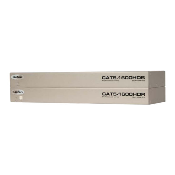
- Page 1 ® CAT5-1600HD EXT-CAT5-1600HD User Manual www.gefen.com...
- Page 2 Notice Gefen LLC reserves the right to make changes in the hard ware, packaging and any accompanying doc u men ta tion without prior written notice. CAT5-1600HD is a trademark of Gefen LLC © 2010 Gefen LLC, All Rights Reserved...
-
Page 3: Table Of Contents
CONTENTS Introduction Operation Notes Features Sender Panel Layout Sender Panel Descriptions Receiver Panel Layout Receiver Panel Descriptions Connecting and Operating the CAT5-1600HD Wiring Diagram Adjusting the Signal Quality 10 Network Cable Wiring Diagram 11 Rack Mount Installation 12 Specifi cations 13 Warranty... -
Page 4: Introduction
Gefen Gefen is a unique product line catering to the growing needs for innovative home theater solutions. We specialize in total integration for your home theater, while also focusing on going above and beyond customer expectations to ensure you get the most from your hardware. -
Page 5: Operation Notes
OPERATION NOTES READ THESE NOTES BEFORE INSTALLING OR OPERATING THE CAT5-1600HD • CAT-6a cables can be used up to 200 feet (60 meters). • CAT-5e cables can be used up to 150 feet (45 meters). • Shielded (STP) CAT-5e/CAT-6a is recommended. However, unshielded (UTP) CAT-5e/CAT-6a is acceptable. -
Page 6: Features
FEATURES Features • Extend any DVI source at 1920x1200 up to 200 feet (60 meters) using CAT- 6a cable. • Extends USB 2.0 compliant devices up to 300 feet • DVI is transmitted digitally for zero signal loss over CAT-5 cable •... -
Page 7: Sender Panel Layout
SENDER PANEL LAYOUT... -
Page 8: Sender Panel Descriptions
SENDER PANEL DESCRIPTIONS Power LED When this LED is lit, power is correctly supplied to the unit. USB Input Supplies USB connection from the host computer to the Sender. Connect a USB cable from an available USB port on the computer to this jack. Host Connected LED When this LED is lit, this indicates that the host computer and the Sender unit are connected together properly. -
Page 9: Receiver Panel Layout
RECEIVER PANEL LAYOUT... -
Page 10: Receiver Panel Descriptions
RECEIVER PANEL DESCRIPTIONS Power LED When this LED is lit, power is correctly supplied to the unit. EQ Trim Pot The EQ trim pot is used to equalize the signal to compensate for the extension distance and the quality/skew variances that are found in different CAT-5e / CAT- 6a cabling brands. -
Page 11: Connecting And Operating The Cat5-1600Hd
The remote computer can now be controlled from the Receiver unit. Wiring Diagram for the CAT5-1600HD CAT-6 CABLE (Up To 200 Ft) CAT-5 CABLE (Up To 200 Ft) USB CABLE DVI CABLE Computer Receiver DVI Monitor Sender USB Mouse USB Keyboard USB External HDD USB Printer EXT-CAT5-1600HD... -
Page 12: Adjusting The Signal Quality
CONNECTING AND OPERATING THE CAT5-1600HD Adjusting the Signal Quality The CAT5-1600HD has an EQ trim pot on the Receiver Unit to compensate for the extension distance and cable skew found in different CAT-5e / CAT-6a cabling brands. If there is no output video or if output video contains video artifacts and/or video noise such as snow, use the steps below to adjust the EQ trim pot. -
Page 13: Network Cable Wiring Diagram
NETWORK CABLE WIRING DIAGRAM Gefen recommends the TIA/EIA-568-B wiring option. Please adhere to the table below when fi eld-terminating the CAT-5e / CAT-6a cable for use with Gefen products. Color Orange / White Orange Green / White Blue Blue / White... -
Page 14: Rack Mount Installation
RACK MOUNT INSTALLATION Rack mount ears are provided for installation of this unit into a 1U rack mount space. Locate the side screws on the unit. Remove the front 2 screws that are located closest to the front of the unit. Using the removed screws, screw the rack mounting bracket into the unit. -
Page 15: Specifi Cations
SPECIFICATIONS Video Amplifi er Bandwidth.................165 MHz Single Link Range..............1080P, 1920 x 1200 Input Video Signal..................1.2V p-p Input DDC Signal................5V p-p (TTL) DVI Connector.......DVI-I (29 pin) female (DVI-D digital signal only) USB Input (Sender)............USB type “B” connector USB Output (Receiver)..........four USB type “A” connectors Link Connectors (2).................RJ-45 Shielded Power Supply....................5V DC Power Consumption..............20W (max.) per unit... -
Page 16: Warranty
Gefen warrants the equipment it manufactures to be free from defects in material and workmanship. If equipment fails because of such defects and Gefen is notifi ed within two (2) years from the date of shipment, Gefen will, at its option, repair or replace the equipment, provided that the equipment has not been subjected to mechanical, electrical, or other abuse or modifi... - Page 17 Rev B2 20600 Nordhoff St., Chatsworth CA 91311 1-800-545-6900 818-772-9100 fax: 818-772-9120 www.gefen.com support@gefen.com...
Need help?
Do you have a question about the EXT-CAT5-1600HD and is the answer not in the manual?
Questions and answers