
Subscribe to Our Youtube Channel
Related Manuals for Godex C-650Plus II


Summary of Contents for Godex C-650Plus II
- Page 1 User Manual C-650Plus II © Godex Europe GmbH – Arnzhäuschen 36 – 42929 Wermelskirchen - Germany...
-
Page 2: User Manual
The symbol shown above, applied to the product or on its packing, indicates that, at end of life, the product is not to be thrown away, or disposed as unsorted municipal waste, but separately collected. Godex encourages owners of information technology (IT) equipment to responsibly recycle their equipment when it is no longer needed. - Page 3 Godex advises the customers not to use products for which the compliance to this safety rules are not warranted. Finally seek your dealer or contact a GODEX office and be sure that are provided you the original Godex branded consumables.
-
Page 4: Eec Regulations
User Manual Canadian D.O.C. Radio Interference Regulation This digital apparatus complies with the Canadian ICES-003 Class B limits for radio frequency emissions. Cet appareil numérique est conforme aux limites de Classe B de la norme NMB-003 du Canada. EEC Regulations This equipment conforms to the essential requirements of EU Directives 2006/95/EC, 2004/108/EC. -
Page 5: Table Of Contents
Canadian D.O.C. Printer Setup Flow Chart Radio Interference Regulation Printer Setup through USB and RS232/C EEC Regulations Ports Table of Contents Godex CDC RS-232 Emulation Driver Printer Presentation Installation Unpacking the Printer FBP-650PII Setup Utility Installation Printer Parts Remote Setup... -
Page 6: Printer Presentation
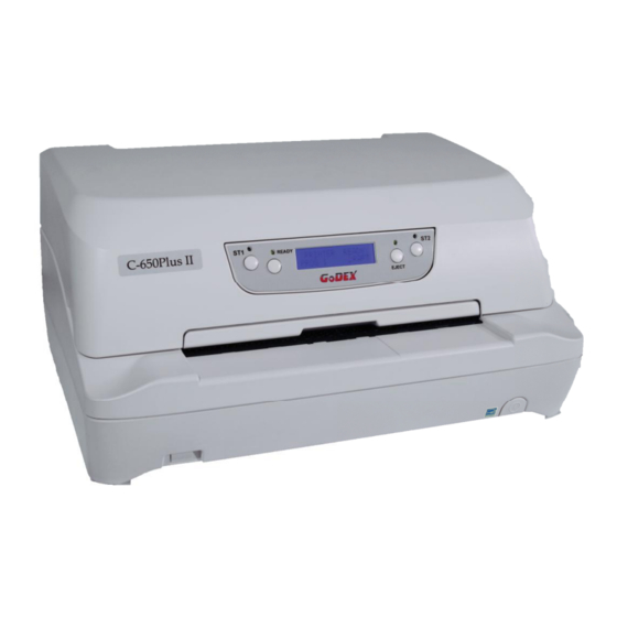
User Manual Printer Presentation This dot-matrix printer is a multi-purpose printer for front office applications. Its compact structure is designed for integration in an ergonomic environment. The printer provides a high level of reliability, form-handling accuracy and data integrity. Its main features are: Printing on a wide range of paper media: different types of cut sheets and multi-parts. -
Page 7: Printer Parts
User Manual Printer Parts Never remove any printer part unless it is expressly indicated in this manual. Front View... -
Page 8: Rear View
User Manual Rear view Inside view Inside View... -
Page 9: Printer Installation
User Manual Printer Installation Choosing a Suitable Location Consider the following points when you choose the location for your printer: The distance between the printer and the host computer must not exceed the length of the interface cable; The location must be sturdy, horizontal and stable; Your printer must not be exposed to direct sunlight, extreme heat, cold, dust or humidity;... -
Page 10: Installing The Ribbon Cartridge
Installing the Ribbon Cartridge In order to avoid damaging the print head or mechanical gearings, this printer accepts only original Godex ribbon cartridges. Therefore, if you install a not original cartridge, the printer may not work. Remove the cartridge from its bag. - Page 11 User Manual Open the upper mechanical frame. Locate the open green lever in the left side of the printer. Unhook the green lever with the left hand towards the rear of the printer in the open position. Then rise up the lever to its maximum position in order to completely open the head assembly.
- Page 12 User Manual The printer is now ready to install the ribbon cartridge. Turn the tension knob in the direction of the arrow to tighten the ribbon. Insert the upper cartridge pins onto the corresponding grooves on both sides of the upper mechanical frame.
- Page 13 User Manual Insert the green plastic ribbon mask onto the print head. Pay attention to match the two pins (2) on both sides of the green ribbon mask with the grooves (1) on both sides of the print head. Push the green ribbon mask up until it clicks into place.
-
Page 14: Paper Handling
User Manual Paper Handling This printer is designed for versatile and reliable paper handling. The flat-bed mechanism allows the handling of special documents, such as multiple invoices, postcards, labels and tickets. The print head detects the paper edges automatically, the sheet can therefore be inserted in any position within the detection area according to the rules described in the following paragraph. -
Page 15: The Operator Panel
User Manual The Operator Panel The operator panel is located in the middle of the printer cover and is composed of function keys and leds with which you can easily check the printer status and select the functions. Function Keys NORMAL MODE SETUP MODE SPECIAL MODE... -
Page 16: Leds
User Manual Leds NORMAL MODE SETUP MODE SPECIAL MODE Lit if paper presence, Unlit without paper If the printer is in Setup Blinks, together with the (no Olivetti). Mode, this led indicates ST2 led, if a printer error “Error When using the IBM 4722, IBM 9068 and which setup page... -
Page 17: Software Driver Selection
User Manual Software Driver Installation At this point it is necessary to configure your printer for your application package. The installation procedures depend upon the host environment. The printer is Plug&Play, therefore when it is connected to a computer under Windows O.S., it automatically discovers the new hardware and it looks in the systems the proper drivers. -
Page 18: Connection To The Host
User Manual Connection to the Host This printer can be connected to the host by means of the following available interface ports: 1. Parallel standard Centronics or bi-directional IEEE 1284 type interface 2. Serial RS-232/C interface 3. USB 2.0 full speed interface Proceed as follows: Make sure that both the host and the printer are turned off. -
Page 19: Setting The Interface Parameters
In case you need to modify the standard parameters see Setup” later in this section. USB Interface Once the Godex FPB-650PII driver has been correctly installed, printer can be immediately used with USB port. “Printer Setup” For a complete description of the printer setup procedure see the paragraph later in this manual. -
Page 20: Printer Setup
User Manual Printer Setup The Printer Setup is used to configure the printer parameters and to print a Self Test page, to check the settings and the printer installation, and to perform the Print Offset Tuning. The default configuration of this printer matches most of the commonly used environments, but it may be necessary to change some printer parameters. -
Page 21: Printing The Self Test Page
User Manual Printing the Test Page The Self Test page is useful to test, if the printer has been correctly installed, and allows to see the current parameter settings. 1. With the printer in the Setup Mode, insert a single sheet in A4 or Letter format. 2. - Page 22 User Manual...
-
Page 23: Printing The Printer Setup Forms
User Manual Printing the Printer Setup Forms If you already have the preprinted forms for the printer setup, go to “Filling in the Printer Setup Forms” later in this manual. 1. With the printer in Setup Mode, insert a blank sheet in A4 or Letter format. 2. - Page 24 User Manual...
- Page 25 User Manual...
-
Page 26: Filling The Printer Setup Forms
User Manual Filling in the Printer Setup Forms To change the values of the parameters, fill in the marker ( ) beside the value you want to set with a black or blue ball-point pen or a fiber-pen. Do not use pencils. AUTOFEED SIGNAL ( ) disabled * enabled... - Page 27 User Manual Setup Parameter Values Description INTERFACE TYPE parallel, serial, opt, usb, Selects the interface type. In case of printer with automatic* optional interface ports are installed, they are listed to be selected. Choosing ‘automatic’ the interface type is selected between all the available interface ports depending on data coming from host.
- Page 28 User Manual Setup Parameter Values Description PROTOCOL EPSON 570*, IBM X24E* Defines the printer protocol. X24E AGM, IBM 2390, NOTE: For the IBM 4722 and 9068 protocols, if OLI. PR40+, OLI. PR2*, the software driver uses the controlled link of OLI.
- Page 29 User Manual Example: How to set the Left Margin to 20. LEFT MARGIN █2 ( )0 ( )1 ( )3 ( )4 ( )5 ( )6 ( )7 ( )8 ( )9 █0 ( )1 ( )3 ( )4 ( )5 ( )6 ( )7 ( )8...
- Page 30 User Manual Setup Parameter Values Description CODE PAGE CP437*, CP437G, 96GREEK, Selects the code page for both the IBM CP850, CP851, CP852, CP853, and the EPSON emulations. CP855, CP857, CP858, CP860, CP862, CP863, CP864, CP865, CP866, CP867, CP876, CP877, CP1098, CP1250, CP1251, CP1252, CP1257, GOST, TASS, MAZOWIA, CP437SL, UKRAIN, KOI8-U, 8859/1, 8859/2, 8859/3,...
- Page 31 User Manual Setup Parameter Values Description SLASHED ZERO No*, yes Selects the printing character for zero, with a slash (yes) or without (no). EJECT ON FF no, yes* Performs a form feed according to the selected page format (no) or ejects a cut sheet loaded into the printer (yes).
-
Page 32: Offset Adjustments
User Manual Offset Adjustments For a precise adjustment of the position of the printed characters on a preprinted form, the printer allows to easily adjust the first line and the first printing column as follows: When the printer is in Setup Mode, insert a blank sheet into the printer press the ST1 key until the leds are in the configuration showed in previous SETUP STATUS table. -
Page 33: Reading The Preprinted Setup Forms
User Manual The Vertical Offset Tuning values correspond to 1/60 inches and set the vertical offset of the first print line starting from the default standard position at 1 mm from the upper paper margin. The Horizontal Offset Tuning values correspond to 1/60 inches and set the horizontal offset of the first print line starting from the default standard position at 3 mm from the left paper margin. -
Page 34: Printer Setup Flow Chart
User Manual Printer Setup Flow Chart Printer Ready Setup Mode Printer OFF # Parameters are set Self Test ●... -
Page 35: Printer Setup Through Usb And Rs232/C Ports
The printer Setup parameters can be changed through normal Setup as described in previous chapter or through USB or Serial 232/C port. For this purpose is necessary install the ”Godex CDC RS-232 Emulation” driver creating a virtual serial port and the “FPB-650PII Setup” software, Windows based utility able to configures the printer through USB (directly) or RS232/C Serial connection (directly or via a serial/USB adapter). - Page 36 User Manual If the installation is positively ended, in the Windows hardware resources a new COMn port will be found.
-
Page 37: Fbp-650Pii Setup Utility Installation
User Manual FBP-650PII Setup utility installation Once the Godex CDC RS-232 Emulation driver has been installed, found the Setup.exe file and double click on it. Follow the steps displayed in the below masks in order to correctly install the utility. -
Page 38: Read Nvm
User Manual Note (*) The first available port number used by the Setup utility is taken from the system registry and can be different from the one displayed. When the Read/Write/Restore MFG action will be run, the following message will be displayed by the operator panel LCD : REMOTE SETUP... -
Page 39: Send Setup
User Manual Write NVM After reading the configuration, it is possible to do all the possible changes simply select the new values. When all modification are done, the new configuration can be stored in the printer NVM pressing the Write NVM action key. -
Page 40: Troubleshooting
User Manual Troubleshooting Paper Problems The straight paper path of this printer is designed for trouble-free handling of a great variety of documents. Paper Jam In case a paper jam condition occurs, proceed as follows: Open the printer cover. And rise the upper mechanical frame as explained in the chapter: Installing the Ribbon Cartridge, page 5. -
Page 41: Paper Damaged After Printing
User Manual In case it is not possible to remove the jammed paper because you cannot reach it with your hand or it is embedded so that you cannot move it, rotate the paper belt to free the paper. Carefully pull down the green lever following the step 3, 4, and 5 in reverse order in order to securely close the Upper Mechanical Frame.If you do not close the Upper Mechanical Frame, the printer does not print correctly. -
Page 42: Error Handling
Recoverable error message description Upper line message Indication Solution Lower line message The ribbon cartridge installed Verify if the ribbon cartridge is a Godex is not genuine or it is wrongly genuine one. RIBBON BROKEN installed. Check that the ribbon is correctly inserted REPLACE RIBBON “Installing the Ribbon... -
Page 43: Not-Recoverable Errors
User Manual Not-Recoverable errors When an error of this kind occurs: 1. The printer is halted with all the four leds flashing. 2. With operator panel with display, the following messages will be displayed; the first line indicates the error, while the second line gives more details concerning the error conditions. Power-off and Power-on the printer. -
Page 44: Ribbon Cartridge Problems
The ribbon cartridge is not an The printer checks the inserted cartridge, to avoid print original Godex cartridge or it is damaging the print head assembly due to incorrect an exhausted cartridge. ribbon feeding. Insert or replace with an original Godex ribbon cartridge. -
Page 45: Paper Specifications
User Manual Paper Specifications The documents must all guarantee the following characteristics: Use paper matching the indicated characteristics. They must have well defined top and left edges, with a square angle tolerance of 0.1° on all edges. The radius on a corner of the form must be within 9.5 mm from the left or right edge. The form to be printed must not contain foreign material. -
Page 46: Technical Specifications
User Manual Technical Specifications Printing Technology 24 pin serial dot matrix printer (needle diameter 0,25 mm) Printing Speed 520 cps (@10 cpi) Draft 400 cps 200 cps 133 cps 94 columns @10 cpi – 112 columns @ 12 cpi – 141 columns @ 15 cpi Line Length Paper Handling Single Sheet, envelopes, labels, (paper weight from 40gr/m... -
Page 47: Serial Interface Connection
User Manual Serial Interface Connection Solder side Solder side view view To PC IBM To printer compatible Female connector Female connector...
Need help?
Do you have a question about the C-650Plus II and is the answer not in the manual?
Questions and answers