Table of Contents
Advertisement
Quick Links
Advertisement
Table of Contents

Related Manuals for Grizzly G0492


Summary of Contents for Grizzly G0492
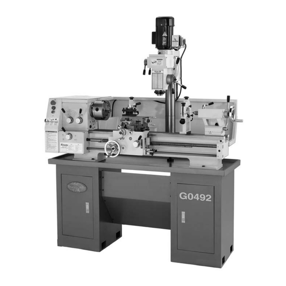
- Page 1 12" X 36" COMBO LATHE/MILL OWNER'S MANUAL COPYRIGHT © AUGUST, 2006 BY GRIZZLY INDUSTRIAL, INC. WARNING: NO PORTION OF THIS MANUAL MAY BE REPRODUCED IN ANY SHAPE OR FORM WITHOUT THE WRITTEN APPROVAL OF GRIZZLY INDUSTRIAL, INC. #CR8520 PRINTED IN CHINA...
- Page 2 ���� ������ �������� �������� ������ ������������ �� ��� ������ ������ ���������� ����������� ��� ������� �� ���� ������������������ ������� �� ����� ���������� ��� ������ ��� ������������ ����� �� ���� ������ ��� ������ �� ������� �������� ������� ��������� ����������� ������������� �� ������ ���...
-
Page 3: Table Of Contents
INTRODUCTION ... 3 Foreword ... 3 Contact Info ... 3 Machine Data Sheet ... 4 Identification ... 6 SECTION 1: SAFETY... 7 Safety Instructions for Machinery ... 7 Additional Safety Instructions for Lathe/Mills ... 9 Glossary of Terms ... 10 SECTION 2: CIRCUIT REQUIREMENTS ... - Page 4 7500 Series Parts List ... 65 Mill Column Diagram ... 66 8000 Series Parts List ... 67 Accessories and Labels Diagram ... 68 9000 Series Parts List ... 69 WARRANTY AND RETURNS ... 70 G0492 12" X 36" Combo Lathe/Mill...
-
Page 5: Introduction
INTRODUCTION Foreword We are proud to offer the Model G0492 12" X 36" Combo Lathe/Mill. This machine is part of a grow- ing Grizzly family of fine metalworking machinery. When used according to the guidelines set forth in this manual, you can expect years of trouble-free, enjoyable operation and proof of Grizzly’s com-... -
Page 6: Machine Data Sheet
Customer Service #: (570) 546-9663 • To Order Call: (800) 523-4777 • Fax #: (800) 438-5901 MODEL G0492 12" X 36" COMBO LATHE/MILL Product Dimensions: Approximate Net Weight ...1200 lbs. Overall Dimensions ... 67-3/4" Wide x 26-3/4" Deep x 72" Tall Footprint ... - Page 7 Drill Chuck ...1-13mm JT-33 4-Jaw Chuck ... 8" 3-Jaw Chuck ... w/Int. & Ext. Jaws, 6" Faceplate: ... 8" Tool Holder ...4-Way Turret Tool Post Change Gears ... Steel Dead Centers ... MT5 & MT3 G0492 12" X 36" Combo Lathe/Mill...
-
Page 8: Identification
K. Milling Rack Handles Steady Rest M. Tailstock N. Lead Screw Identification G0492 12" X 36" Combo Lathe/Mill. P. Chip Tray and Drip Pan Q. Longitudinal and Cross slide Lever R. Spindle ON/OFF Rotation Lever S. Thread Dial Half Nut Lever U. -
Page 9: Section 1: Safety
������������������� �� ������ ���� � ����� �������� ���������� ���� ��������� ���� �������� ������ ���������������������������������������� ���������������������������������������� G0492 12" X 36" Combo Lathe/Mill �� ������ ��� ������� ���������� ���� ���������� ���������� ������ ���� ������ ���������� ���������������� �� ���� ������ ��������� ��� ����... - Page 10 �� ���������� ��� ���� ������������ ���� ����� ��� ������� ���� ��������� ����������� � ������������������������������������������ ��������������������������������������������� �������� ��� ���� ������� ����� �� ����������� ��������������������������������� ��������� ���� ��� ��� ������� ����� ���� ������ ����� ����� ������ ��������� G0492 12" X 36" Combo Lathe/Mill...
-
Page 11: Additional Safety Instructions For Lathe/Mills
If normal safety precautions are overlooked or ignored, seri- ous personal injury may occur. G0492 12" X 36" Combo Lathe/Mill PREVENTING APRON-CHUCK CRASH: Always release automatic feeds after completing a job. -
Page 12: Glossary Of Terms
The following is a list of common definitions, terms and phrases used throughout this manual as they relate to this lathe/mill and metalworking in general. Become familiar with these terms for assembling, adjusting or operating this machine. Your safety is VERY important to us at Grizzly! Arbor: A machine shaft that supports a cutting tool. -
Page 13: Section 2: Circuit Requirements
DO NOT connect the machine to the power source until instructed to do so. Amperage Draw Combined, both of the G0492 Lathe/Mill motors draw the following amps under maximum load: Both Motors Operating ... 17 Amps Circuit Requirements... -
Page 14: Section 3: Set Up
Ignoring this warning may lead to serious personal injury or death. Unpacking and Lifting The Model G0492 was carefully packed when it left our warehouse. If you discover the machine is damaged after you have signed for delivery, please immediately call Customer Service at (570) 546-9663 for advice. -
Page 15: Inventory
— Change Gear (50-tooth, Installed) ... 1 — Change Gear (52-tooth) ... 1 — Change Gear (60-tooth, Installed) ... 1 G0492 12" X 36" Combo Lathe/Mill Figure 3. Installed accessories. Figure 4. Packaged accessories. In the event that any nonproprietary parts are missing (e.g. -
Page 16: Site Considerations
Lack of ventilation while using these sol- vents could cause seri- ous personal health risks or fire. Take precautions from this hazard by only using cleaning solvents in a well ventilated area. ��� ��������� ����� ��� G0492 12" X 36" Combo Lathe/Mill... -
Page 17: Section 4: Lathe Operations
OMMEND that you read books, trade maga- zines, or get formal training before begin- ning any projects. Regardless of the con- tent in this section, Grizzly Industrial will not be held liable for accidents caused by lack of training. NOTICE Complete the Test Run &... -
Page 18: Test Run & Break-In
11. Change the lubricant in the headstock with Mobil DTE Feed Lever Half-Nut Lever Spindle Rotation ON/OFF lever. Figure 8. Apron control levers. problem is not readily apparent, Oil or with an equivalent. ® G0492 12" X 36" Combo Lathe/Mill... -
Page 19: Mounting The Chuck And The Faceplate
(see Figure 9). Figure 9. Simple chuck cradle made of scrap lumber. G0492 12" X 36" Combo Lathe/Mill Use a 14mm wrench and loosen the three hex bolts that secure the chuck to the spindle Figure 10. -
Page 20: Replacing The Jaws
Repeat the steps on the remaining jaws. — If installed correctly, the three jaws will converge together at the center of the chuck. — If the jaws do not come together, repeat this procedure until they do. G0492 12" X 36" Combo Lathe/Mill... -
Page 21: Using The Four-Jaw Chuck
(see Figure 14). Figure 14. Clamping workpiece. G0492 12" X 36" Combo Lathe/Mill Turn each jaw until it just makes contact with the workpiece. In an opposing pattern, tighten each jaw in small increments. -
Page 22: Using The Faceplate
-20- Figure 16. Faceplate installed. Use a minimum of three independent clamping devices when turning eccentric workpieces. Failure to provide adequate clamping will cause workpiece to eject. G0492 12" X 36" Combo Lathe/Mill... -
Page 23: Using The Tailstock
Offset Adjustment Offset Scale Figure 17. Tailstock and quill lock handles in locked position. G0492 12" X 36" Combo Lathe/Mill Drilling with the Tailstock To install the MT#3 drill chuck: With the tailstock locked, unlock the quill lock lever. Turn the quill feed handle clockwise to extend the quill about one inch. -
Page 24: Cutting Shallow Tapers With Tailstock
Adjustment true to the spindle axis. Keep in mind that the point will have to be refinished whenever it is removed and returned to the chuck. Figure 21. Tailstock centering dead center. G0492 12" X 36" Combo Lathe/Mill... - Page 25 (see Figure 22). Figure 22. Tailstock adjustment option #1. G0492 12" X 36" Combo Lathe/Mill —If the stock diameter is thinner at the tailstock end, the tailstock needs to be moved away from you half the distance of the amount of the taper (see Figure 23).
-
Page 26: Using The Centers
Figure 25. Faceplate and dead center setup. NOTICE Failure to keep dead center point well lubricated will gall the dead center and workpiece. G0492 12" X 36" Combo Lathe/Mill... -
Page 27: Using The Steady Rest
After prolonged use, the fingers will show wear. Either mill or file the tips for a new con- tact surface. G0492 12" X 36" Combo Lathe/Mill Using the Follow The follow rest in Figure 27 is mounted on the saddle and follows the movement of the tool. The follow rest requires only two fingers, as the cut- ting tool acts as the third. -
Page 28: Using The Compound Rest
This is accomplished by rotating the top handle counterclockwise and then rotating the tool post to the desired position. Rotate the top handle clockwise to lock the tool into position. Figure 29. Four-way tool post. G0492 12" X 36" Combo Lathe/Mill... -
Page 29: Using The Manual Feed Handwheels
Angle adjustment is held by two hex nuts on the base of the compound rest. G0492 12" X 36" Combo Lathe/Mill Setting the Spindle To determine and set the needed spindle... - Page 30 — The RPM Lever selects the RPM within that range. -28- Note: You may need to rotate the chuck by hand to get the gears to engage. RPM Lever RPM/Range Chart Figure 32. Spindle speed selector levers. G0492 12" X 36" Combo Lathe/Mill Range Lever...
-
Page 31: Setting The Power Feed Rate
Note: All change gears are stamped with the number of teeth they have. G0492 12" X 36" Combo Lathe/Mill Loosen the lash adjuster (Figure 33) and swing the assembly out of the way. Remove the required E-clips, lubricate, and swap out the appropriate change gears. -
Page 32: Setup For Threading
1 or 2 1 or 2 11.5 1 or 2 12.5 1 or 2 1 or 2 1 or 2 1 or 2 1 or 2 1 or 2 Figure 38. Thread dial table. G0492 12" X 36" Combo Lathe/Mill... -
Page 33: Change Gear Chart
Change Gear Chart -31- G0492 12" X 36" Combo Lathe/Mill... -
Page 34: Section 5: Mill Operations
Figure 39. Start switch location. -32- Turn the spindle ON and run it a minimum of 10 minutes. Repeat this step on the other three RPM ranges. Milling Speed Levers Quill Feed Lever Figure 40. Gearbox and controls. G0492 12" X 36" Combo Lathe/Mill... -
Page 35: Positioning The Headstock
Lock Nut Figure 42. Headstock lock nut. Using the Mill Table The mill table of the Model G0492 can be moved in two axes—cross slide and longitudinal feed. Each of these axes are controlled by graduated handwheels to accurately position the workpiece in relation to the tool. -
Page 36: Installing Cutters
Prepare to catch the arbor, and unscrew the drawbar until the arbor drops into your hand. Drawbar Figure 45. The drawbar. NOTICE G0492 12" X 36" Combo Lathe/Mill... -
Page 37: Setting The Spindle Rpm
Use the following formula to determine the needed RPM for your operation: (Cutting Speed x 4) / Tool Diameter = RPM G0492 12" X 36" Combo Lathe/Mill Note: You will only be able to get an approxi- mate RPM value with the variable speed knob. -
Page 38: Section 6: Maintenance
To control surface rust on machined surfaces, wipe the unprotected metal as required with a rust inhibiting oil. Headstock Oil Fill Plug Figure 49. Headstock fill plug. Headstock Oil Level Sight Glass G0492 12" X 36" Combo Lathe/Mill... -
Page 39: Belt Adjustment Or Replacement
Change Gear Spindle (1 ball oiler on end of shaft) • Gear Spindle Ball Oiler (1 ball oiler, see Figure 48) • Gearbox (4 ball oilers on top) Figure 51. Typical ball fitting locations. Figure 52. Lead screw end cap bushing. G0492 12" X 36" Combo Lathe/Mill -37-... -
Page 40: Section 7: Service
Tighten the jam nuts when finished. Cross Slide Gib Adjustment Point Saddle Gib Adjustment Points Figure 55. Gib adjustment points. Figure 56. Half-nut gib adjustment location. G0492 12" X 36" Combo Lathe/Mill... -
Page 41: Electrical Component And Connection Index
Electrical Component and Connection Index Figure 57. G0492 Electrical panel. -39- G0492 12" X 36" Combo Lathe/Mill... -
Page 42: Electrical Connections
Figure 60. Contactor wiring (KM2 and KM3). Figure 58. Contactor wiring (KM1). Figure 61 Contactor wiring (KM2 and KM3). Figure 59. Junction block wiring. Figure 62 Junction block wiring. Figure 63 Junction block wiring. -40- G0492 12" X 36" Combo Lathe/Mill... - Page 43 Electrical Connections Figure 67. Transformer output connection. Figure 64. Motor connection. Figure 68. Transformer input connection. Figure 65. Start capacitor. Figure 66. Mill power switch. Figure 69. Lathe motor direction limit switches. -41- G0492 12" X 36" Combo Lathe/Mill...
-
Page 44: 220V Wiring Diagram
Electrical Connections Emergency Stop Switch Power Lamp Jog Button Figure . Lathe controls. Figure . Lathe control panel wiring. 220V Wiring Diagram -42- G0492 12" X 36" Combo Lathe/Mill... -
Page 45: Troubleshooting
3. Too much play in gibs. Gear change 1. Gears not aligned in headstock. levers will not shift into position. G0492 12" X 36" Combo Lathe/Mill Troubleshooting Possible Solution 1. Use the spindle direction ON/OFF lever. 2. Turn the main power panel switch ON. - Page 46 4. Lower the tool position. 1. Realign the tailstock to the headstock spindle bore center line. 1. Remove jaws, clean and lubricate chuck threads, and replace jaws. 1. Adjust gear positions. 2. Replace. 3. Tighten. screw(s) slightly, lubricate G0492 12" X 36" Combo Lathe/Mill...
- Page 47 2. Chips have loaded up on bedways. 3. Bedways are dry and in need of lubrication. 4. Longitudinal stops are interfering. 5. Gibs are too tight. G0492 12" X 36" Combo Lathe/Mill Troubleshooting Possible Solution 1. Inspect keys and setscrews. Replace or tighten if necessary.
-
Page 48: Section 8: Accessories
1 Qt. Gel ® 12 oz Spray ® T-9 12 oz Spray ® T-9 4 oz Spray ® Gun Treatment 12 oz Spray ® Gun Treatment 4.5 oz Spray ® G0492 12" X 36" Combo Lathe/Mill... -
Page 49: Section 9: Parts
P04920002 CONTACTOR (LC1-D1201, B5, 24V, 50HZ) P04920003 CONTACTOR (LC1-D1201, B5, 24V, 50HZ) P04920004 TRANSFORMER (JBK5-63), (INPUT 220V +/- 5%, OUTPUT 24V) G0492 12" X 36" Combo Lathe/Mill Electrical Box (0000 Series Parts) PART # P04920006 P04920007 P04920008 P04920009 P04920010 10-1... -
Page 50: Lathe Change Gear Housing Diagram
Lathe Change Gear Housing Diagram (1000 Series Parts) -48- G0492 12" X 36" Combo Lathe/Mill... -
Page 51: 1000 Series Parts List
P04921031 IDLER SHAFT 1032 PW06M FLAT WASHER 12MM 1033 PEC12M E-CLIP 12MM 1034 P04921034 IDLER SHAFT G0492 12" X 36" Combo Lathe/Mill PART # DESCRIPTION 1035 P04921035 LONG SPLINED WEAR BUSHING 1036 P04921036 CHANGE GEAR (60-TOOTH) 1037 P04921037 SPACER SLEEVE... -
Page 52: Leadscrew Gearbox Diagram
Leadscrew Gearbox Diagram (2700 Series Parts) -50- G0492 12" X 36" Combo Lathe/Mill... -
Page 53: 2700 Series Parts List
PK126M KEY 5 X 5 X 32 2724 P04922724 SHAFT 2725 P8102 BEARING 8102 2726 P04922726 FLANGE HUB G0492 12" X 36" Combo Lathe/Mill PART # DESCRIPTION 2727 PSB24M CAP SCREW M5-.8 X 16 2728 P8102 BEARING 8102 2729 P04922729... -
Page 54: Thread Dial Diagram
Thread Dial Diagram (3000 Series Parts) -52- G0492 12" X 36" Combo Lathe/Mill... -
Page 55: 3000 Series Parts List
P04923052 OUTPUT SHAFT 3053 P04923053 HUGE GEAR (68-TOOTH) 3054 P04923054 GEAR (33-TOOTH) 3055 P04923055 GEAR (56-TOOTH) G0492 12" X 36" Combo Lathe/Mill PART # DESCRIPTION 3056 KEY 5 X 5 X 60 PK128M 3057 P04923057 SPACER SLEEVE 3058 P04923011 BALL BEARING 203... -
Page 56: Compound Rest And Tool Post Diagram
���� ���� ���� ���� ���� ���� ���� ���� ���� ���� ���� ���� ���� ���� ���� ���� ���� ���� ���� ���� ���� ���� ���� ���� ���� ���� ���� ���� ���� ���� ���� ���� ���� -54- G0492 12" X 36" Combo Lathe/Mill... -
Page 57: 3500 Series Parts List
CAP SCREW M6-1 X 16 3517 P04923517 END BLOCK 3518 P04923518 SCALE HUB 3519 P04923519 FLAT SPRING 3520 P04923520 G0492 12" X 36" Combo Lathe/Mill PART # DESCRIPTION 3521 P04923521 SPANNER NUT 3522 P04923522 TAPERED PIN 3523 P04923523 HANDLE ASSY... -
Page 58: Bed Diagram
Bed Diagram (4000 Series Parts) -56- G0492 12" X 36" Combo Lathe/Mill... -
Page 59: 4000 Series Parts List
P04924039 L-BLOCK SMALL 4040 P04924040 CARRIAGE 4041 P04924041 WIPER 4042 P04924042 WIPER 4043 P04924028 BALL OILER 6MM G0492 12" X 36" Combo Lathe/Mill PART # DESCRIPTION 4044 P04924044 CROSS NUT 4045 P04924045 WORKTABLE 4046 P04924046 LONGITUDINAL FEED SCREW 4047 P04924047... -
Page 60: Steady Rest And Follow Rest Diagram
���� ���� ���� ���� ���� ���� ���� ���� ���� ���� ���� ���� ���� ���� ���� ���� ���� ���� ���� ���� ���� ���� ���� ���� ���� ���� ���� ���� ���� ���� ���� ���� ���� -58- G0492 12" X 36" Combo Lathe/Mill... -
Page 61: 4500 Series Parts List
P04924510 STEADY REST HEAD 4511 PW01M FLAT WASHER 8MM 4512 P04924512 STEADY REST BASE 4513 P04924513 FEMALE KNOB M8-1.25 G0492 12" X 36" Combo Lathe/Mill PART # DESCRIPTION 4514 P04924514 SPECIAL EYE BOLT 4515 PW04M FLAT WASHER 10MM 4516 PN02M HEX NUT M10-1.5... -
Page 62: Tailstock Diagram
5723 5722 5717 5721 5720 5719 5718 5714 5730 5713 5712 5739 5731 5711 5710 5732 5740 5733 5741 5709 5734 5708 5707 5706 5735 5705 5704 5703 5736 5702 5701 5737 5738 -60- G0492 12" X 36" Combo Lathe/Mill... -
Page 63: 5700 Series Parts List
TAILSTOCK HOUSING 5719 P04925719 TAILSTOCK STEM 5720 PK125M KEY 4 X 4 X 28 5721 P04925721 FLANGE HUB G0492 12" X 36" Combo Lathe/Mill PART # DESCRIPTION 5722 P04921028 BALL OILER 6MM 5723 PSB33M CAP SCREW M5-.8 X 12 5724... -
Page 64: Apron Diagram
Apron Diagram (6000 Series Parts) -62- G0492 12" X 36" Combo Lathe/Mill... -
Page 65: 6000 Series Parts List
PFH25M FLAT HD SCR M4-.7 X 12 6038 P04926038 KNOB M8-1.25 FEMALE 6039 P04926039 LEVER 6040 P04926040 LEVER HUB G0492 12" X 36" Combo Lathe/Mill PART # DESCRIPTION 6041 P04926041 COMPRESSION SPRING 6042 P04926042 STEEL BALL 6.5MM 6043 P04926043 SPECIAL SET SCREW M6-1.0 X 8... -
Page 66: Headstock Diagram
Headstock Diagram (7500 Series Parts) -64- G0492 12" X 36" Combo Lathe/Mill... -
Page 67: 7500 Series Parts List
P04927543 MOTOR 220V 3/4 HP 7543-1 P04927543-1 CAPACITOR 200UF/250VAC 7543-2 P04927543-2 FAN COVER 7543-3 P04927543-3 FAN 7543-4 P04927543-4 POWER SWITCH (KJD12, 230VAC, 5E4) G0492 12" X 36" Combo Lathe/Mill PART # DESCRIPTION 7543-5 P04927543-5 POWER SWITCH BOX 7544 PW04M FLAT WASHER 10MM... -
Page 68: Mill Column Diagram
8013 8012 8011 8010 8009 8008 8007 8006 8005 8004 8003 8002 8001 -66- (8000 Series Parts) 8014 8015 8016 8027 8026 8025 8017 8018 8030 8019 8029 8020 8028 8021 8022 8023 8024 G0492 12" X 36" Combo Lathe/Mill... -
Page 69: 8000 Series Parts List
TANG WASHER 8013 P04928013 SPANNER NUT M30-1.5 8014 PN41M ACORN NUT M10-1.5 8015 P04928015 HAND WHEEL G0492 12" X 36" Combo Lathe/Mill PART # DESCRIPTION 8016 P8103 BALL BEARING 8103 8017 PK69M KEY 4 X 4 X 12 8018 P04928018... -
Page 70: Accessories And Labels Diagram
9048 9006 9007 9022 9015 9010 9047 9046 9008 9001 9033 9045 9023 9044 9021 9011 9039 9040 9041 9038 9024 9034 9037 9032 9025 9026 9030 9043 9028 9027 9035 9031 9029 -68- G0492 12" X 36" Combo Lathe/Mill... -
Page 71: 9000 Series Parts List
P04929016 DEAD CENTER MT#3 9017 P04929017 THREE-JAW CHUCK INT. JAWS 9020 P04929020 ARBOR JT-33 TO MT#3 9021 P04929021 SPOT PAINT G0492 12" X 36" Combo Lathe/Mill PART # DESCRIPTION 9022 P04929022 DRILL CHUCK KEY 9023 P04929023 BACK SPLASH 9024 P04929024... -
Page 72: Warranty And Returns
WARRANTY AND RETURNS Grizzly Industrial, Inc. warrants every product it sells for a period of 1 year to the original purchaser from the date of purchase. This warranty does not apply to defects due directly or indirectly to misuse, abuse, negligence, accidents, repairs or alterations or lack of maintenance. - Page 73 ��� �������������������������������������������������������������������������������������� ����� �� ����� ��� ����� ���� ���� � ������� � ���� ��������� ��������������������������������������������������������������������� ��������������������������������������������������������������������������������� ��������������������������������������������������������������������������������� ��������������������������������������������������������������������������������� G0492 12" X 36" Combo Lathe/Mill �������� ���� � ���� ������� � ���� �������� ���� ����������������� ���� ��������������� ���� ������������������� ���� �������������������...
- Page 74 ���������������������� ���������������������� ����������������������������������� ������� ����������� ���� ���� ��� ���� ����������� �� ���������� ����������������������������������� ������������������������������������� �������������������������������������� �������������������������������������� ����� ����� ����...
- Page 76 ��� ������ ��� ���� ���� ������� ����� ��� ������� ����� ��� �������� ��� ������� � ������ �������� � ������ ������� ������ �� ����� � ������ �������� ������ ��� ���� ���� ����� ��� � � �������� ������ ��� � ����� ������ �...
Need help?
Do you have a question about the G0492 and is the answer not in the manual?
Questions and answers