
Related Manuals for Grizzly G0492


Summary of Contents for Grizzly G0492
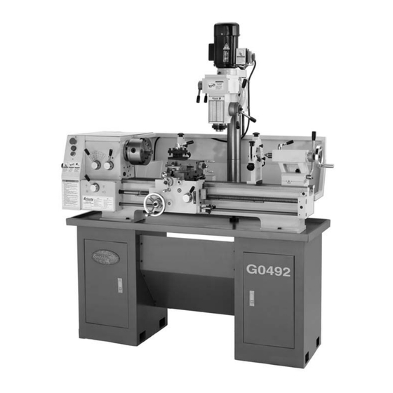
- Page 1 MODEL G0492 12" X 36" COMBO LATHE/MILL OWNER'S MANUAL WARNING: NO PORTION OF THIS MANUAL MAY BE REPRODUCED IN ANY SHAPE OR FORM WITHOUT THE WRITTEN APPROVAL OF GRIZZLY INDUSTRIAL, INC.
-
Page 3: Table Of Contents
INTRODUCTION ... 2 SECTION 1: SAFETY ... 7 SECTION 2: CIRCUIT REQUIREMENTS ... 11 SECTION 3: SET UP ... 12 SECTION 4: LATHE OPERATIONS ... 15 SECTION 5: MILL OPERATIONS ... 32 Table of Contents SECTION 6: MAINTENANCE ... 36 SECTION 7: SERVICE ... -
Page 4: Introduction
INTRODUCTION Foreword Contact Info www. grizzly.com... -
Page 5: Machine Data Sheet
Customer Service #: (570) 546-9663 · To Order Call: (800) 523-4777 · Fax #: (800) 438-5901 MODEL G0492 12" X 36" METAL LATHE W/ MILLING HEAD Weight... 1200 lbs. Length/Width/Height... 67-3/4 x 26-3/4 x 72 in. Foot Print (Length/Width)... 59-1/4 x 16-1/2 in. - Page 6 Type... TEFC Capacitor Start Induction Horsepower...1-1/2 HP Voltage...220V Prewired...220V Phase... Single Amps...7.5A Speed...1725 RPM Cycle...60 Hz Number Of Speeds... 1 Power Transfer ...V-Belt Bearings... Shielded and Lubricated Chuck Type...3-Jaw, 4-Jaw Chuck Size... 6, 8 in. Faceplate Size...8 in. Tailstock Taper... MT#3 Tailstock Travel...
- Page 7 Bed Const... Hardened and Ground Cast Iron Headstock Const... Cast Iron Body Const... Cast Iron Frame Const...Cast Iron Headstock Gears Const...Steel Stand Const...Formed Steel Paint... Epoxy Bed Width...6-1/2 in. Floor To Center Height...43-1/2 in. Lead Screw Diameter...1 in. Lead Screw TPI...5 Lead Screw Length...
- Page 8 Identification...
-
Page 11: Additional Safety For Lathe/Mills
Additional Safety for Lathe/Mills UNDERSTANDING THE MACHINE: CLEANING MACHINE: USING CORRECT TOOLING: ELIMINATING A PROJECTILE HAZARD: SECURING A WORKPIECE: AVOIDING OVERLOADS: MAINTAINING A SAFE WORKPLACE: Like all machinery there is potential danger when operating this machine. Accidents are frequently caused by lack of familiarity or failure to pay attention. -
Page 12: Glossary Of Terms
Glossary of Terms Arbor: Backlash: Collet: Cross Slide: Cutting Speed: Dial Indicator: Dividing Head: Down Milling or Climb Milling: End Mill: Facing: Feed: Fixture: VERY Gib: Headstock: Lathe Center: Leadscrew: Spindle: Tailstock: Tool Post: Turret: Ways:... -
Page 13: Section 2: Circuit Requirements
SECTION 2: CIRCUIT REQUIREMENTS 220V Singe-Phase Operation Serious personal injury could occur if you connect the machine to power before com- pleting the setup process. DO NOT connect the machine to the power until instructed later in this manual. Electrocution or fire could result if machine is not grounded and installed in compliance with electrical... -
Page 14: Section 3: Set Up
SECTION 3: SET UP Set Up Safety The Model G0492 weighs approximately 1200 lbs. You will need power lifting equip- ment and assistance to remove this machine from the pallet and position it. Inspect all lifting equipment and make sure that all is... - Page 15 Inventory Installed Accessories (Figure 3) ... Qty. Packaged Accessories (Figure 4) Figure 3. Figure 4. NOTICE Some hardware/fasteners on the inventory list may arrive pre-installed on the machine. Check these locations before assuming that any items from the inventory list are miss- ing.
-
Page 16: Site Considerations
Site Considerations Floor Load Placement Location Figure 5 Unsupervised children and visitors inside your shop could cause serious per- sonal injury to themselves. Lock all entrances to the shop when you are away and DO NOT allow unsupervised children or visitors in your shop at any time! Figure 5. -
Page 17: Section 4: Lathe Operations
OMMEND that you read books, trade maga- zines, or get formal training before begin- ning any projects. Regardless of the con- tent in this section, Grizzly Industrial will not be held liable for accidents caused by lack of training. NOTICE Complete the Test Run &... -
Page 18: Test Run & Break-In
Test Run & Break-In NOTICE Make sure all power feed levers and dials are disengaged before starting the lathe/ mill! Thoroughly familiarize yourself with all the controls and their functions before using any power feed! NEVER SHIFT LATHE/MILL GEARS WHEN MACHINE IS OPERATING. To begin the test run &... -
Page 19: Mounting The Chuck And The Faceplate
Mounting the Chuck and the Faceplate To remove and install the chuck or face plate: Figure 9. Figure 10. Figure 10. Figure 9 Securely clamp your workpiece and remove the chuck key! Thrown objects from a lathe/ mill can cause serious injury or death to the operator and to bystanders many feet away. -
Page 20: Replacing The Jaws
Replacing the Jaws Figure 11 Figure 11. Figure 12. Note: The chuck need not be removed from the spindle to swap the jaws. To remove a set of jaws: Figure 12 Figure 13. Figure 13... - Page 21 Using the Four-Jaw Chuck To install the four-jaw chuck: Mounting the Chuck and Faceplate Page 17 To load a workpiece in the four-jaw chuck: Figure 14 Figure 14. Figure 15 Figure 15. Securely clamp your workpiece and remove the chuck key! Thrown objects from a lathe/ mill can cause serious injury or death to the operator and to...
-
Page 22: Using The Faceplate
Using the Faceplate To install the faceplate: Mounting the Chuck and Faceplate Page 17 To load a workpiece: Note: Depending on the workpiece, some additional support may be needed. Make sure your clamping application will not fail! Securely clamp your workpiece and remove the chuck key! Thrown objects from a lathe/ mill can cause serious injury... -
Page 23: Using The Tailstock
Using the Tailstock Figure 17 To use the tailstock: Figure 17. Drilling with the Tailstock To install the MT#3 drill chuck: Figure 18 Figure 18. -
Page 24: Aligning Tailstock
Cutting Shallow Tapers with Tailstock To setup the tailstock to cut tapers: Note: To return the tailstock back to the original position, repeat the process until the centered position is indicated on the scale. Figure 19. Figure 20. Aligning Tailstock To align the tailstock: Figures 19 Note: As long as the dead center remains in... - Page 25 Figure 22 Figure 22. Figure 23. Figure 23...
-
Page 26: Using The Centers
Using the Centers To install a dead or live center: Figure 24 Figure 24. Note: Make sure there is a center drilled hole in the end of the workpiece for the dead cen- ter. To install the MT#5 dead center in the spin- dle: Figure 25 Note: When using the dead center in the... - Page 27 Using the Steady Using the Follow Rest Rest Figure 27 To use the steady rest: Figure 26 Figure 26. Figure 27. Figure 26 Figure 26...
-
Page 28: Using The Tool Post
Using the Using the Tool Post Compound Rest Figure 29 To set the angular position: Figure 28 Figure 29. Figure 28. -
Page 29: Using The Manual Feed Handwheels
Using the Manual Feed Handwheels Figure 30 Figure 30. Longitudinal Handwheel Cross Slide Handwheel Compound Rest Handwheel Setting the Spindle To determine and set the needed spindle RPM for cutting: Figure 31 Cutting Speeds for High Speed Steel (HSS) Cutting Tools Note: For carbide cutting tools, double the cutting speed. - Page 30 (Cutting Speed x 4) = RPM Diameter of Cut Figure 32 Note: You may need to rotate the chuck by hand to get the gears to engage. Figure 32.
- Page 31 Setting Power Feed Rate NOTICE Feed rate is based on spindle RPM. Pay close attention to the feed rate you have chosen and be ready to disengage the apron. Failure to do this may cause the carriage to crash into the chuck. To set and engage the power feed: Change Gear Chart Figure 33...
-
Page 32: Setup For Threading
Setup for Threading To setup for threading: Change Gear Chart Figure 36 Note: All change gears are stamped with the number of teeth they have. Figure 36. Page 31 Dial Table Figure 33 Figure 37 Figure 35 Figure 37. Figure 38 THREAD DIAL TABLE LEAD SCREW PITCH 5 T.P.I. - Page 33 Change Gear Chart Change Gear Chart...
-
Page 34: Section 5: Mill Operations
SECTION 5: MILL OPERATIONS Test Run & Break-In NOTICE Failure to follow start up and spindle break- in procedures will cause rapid deterioration of spindle and other related parts, and never shift gears while lathe or mill is running. To begin the start up procedure: ON Figure 39 Figure 39. -
Page 35: Using The Mill Table
Positioning the Headstock To position the spindle head vertically: Figure 41 Figure 41. The headstock is heavy. Make sure that you support the headstock before you loosen the lock nuts. Ignoring this warning may allow the headstock to uncontrolla- bly swing over to the right or left causing injury or severe lathe/mill damage. -
Page 36: Installing Cutters
Installing Cutters To install a cutter in the spindle: Figure 45 Note: Overtightening the drawbar makes removal difficult and stretches the threads of the arbor and the drawbar. Figure 44. Figure 45. Figure Removing Cutters To remove a cutter from the spindle: NOTICE DO NOT completely unscrew the drawbar prior to striking the drawbar or the initial... -
Page 37: Using The Mill
Setting the Spindle NOTICE Never shift gears while lathe or mill is running; otherwise, the gear teeth will be chipped or broken. To determine and set the mill to the needed cutting RPM: Figure 46 Cutting Speeds for High Speed Steel (HSS) cutting tools: Figure 46. -
Page 38: Section 6: Maintenance
SECTION 6: MAINTENANCE Basic Maintenance Check for the following conditions and repair or replace when necessary: Figure 49. General Lubrication Figure 48 Figure 50. General Cleaning Figure 48. Figures 49 and 50... -
Page 39: Belt Adjustment Or Replacement
Figure 51 Figure 52 Figure 48 Figure 51. Figure 52. Belt Adjustment or Replacement To replace or adjust the V-belts: Figure 53 Figure 53 Figure 53. Figure... -
Page 40: Section 7: Service
SECTION 7: SERVICE Cross Slide Backlash Adjustment Note: Avoid the temptation to overtighten the cross slide backlash screw. Overtightening will cause excessive wear to the sliding block and lead screw. Figure 54 Figure 54. Note: Reducing backlash to less than 0.001" is impractical and reduces the life of the cross slide. -
Page 41: Electrical Components
Electrical Components Figure Figure Figure Figure Figure Figure 57. Figure 61 Figure Figure Figure... -
Page 42: Electrical Connections
Electrical Connections Figure 60. Figure 58. Figure 61 Figure 59. Figure 62 Figure 63... - Page 43 Electrical Connections Figure 67. Figure 64. Figure 68. Figure 65. Figure 66. Figure 69.
-
Page 44: 220V Wiring Diagram
Electrical Connections Figure Figure 220V Wiring Diagram... -
Page 45: Troubleshooting
Troubleshooting Motor & Electrical... - Page 46 Troubleshooting Operation and Work Results...
- Page 47 Troubleshooting Operation and Work Results (Continued)
-
Page 48: Section 8: Accessories
SECTION 8: ACCESSORIES H2689—R8 Quick Change Collet Set Figure 72. G9760—20-PC. 2 & 4 Flute TiN End Mill Set. Figure 73. H4959—Coolant Dispenser Figure 74. ® G5562—SLIPIT 1 Qt. Gel G5563—SLIPIT ® 12 oz Spray ® G2871—Boeshield T-9 12 oz Spray G2870—Boeshield ®... -
Page 49: Section 9: Parts
SECTION 9: PARTS 0000 Series Parts List PART # DESCRIPTION P04920001 CONTACTOR (LC1-D0910, B5, 24V, 50HZ) P04920002 CONTACTOR (LC1-D1201, B5, 24V, 50HZ) P04920003 CONTACTOR (LC1-D1201, B5, 24V, 50HZ) P04920004 TRANSFORMER (JBK5-63), (INPUT 220V +/- 5%, OUTPUT 24V) Electrical Box (0000 Series Parts) PART # P04920006 P04920007... -
Page 50: Lathe Change Gear Housing Diagram
Lathe Change Gear Housing Diagram (1000 Series Parts) -
Page 51: 1000 Series Parts List
1000 Series Parts List PART # DESCRIPTION 1001 PS38M PHLP HD SCR M4-.7 X 10 1002 PLW02M LOCK WASHER 4MM 1003 PN04M HEX NUT M4-.7 1004 P04921004 HINGE 1005 P04921005 DOOR 1005-1 P04921005-1 CHANGE GEAR CHART 1006 PVA71 V-BELT A-71 4L710 1007 P04921007 MOTOR PULLEY... -
Page 52: Leadscrew Gearbox Diagram
Leadscrew Gearbox Diagram (2700 Series Parts) -
Page 53: 2700 Series Parts List
2700 Series Parts List PART # DESCRIPTION 2701 P04922701 COVER PLATE 2702 PS05M PHLP HD SCR M5-.8 X 8 2703 P04922703 BALL OILER 8MM 2704 P04922704 SPECIAL SET SCREW M5-.8 X 6 2705 P04922705 SHAFT 2706 PK08M KEY 5 X 5 X 16 2707 P04922707 GEAR (20-TOOTH) - Page 54 Lathe Headstock Diagram (3000 Series Parts)
-
Page 55: 3000 Series Parts List
3000 Series Parts List PART # DESCRIPTION 3001 P04923001 SPANNER NUT M16-1.5 3002 P04923002 TANG WASHER 3003 PW08M FLAT WASHER 16MM 3004 PK08M KEY 5 X 5 X 16 3005 P04923005 SPINDLE PULLEY 3006 P04923006 TAPER ROLLER BEARING 60206 3007 PSB33M CAP SCREW M5-.8 X 12 3008... -
Page 56: Compound Rest And Tool Post Diagram
Compound Rest and Tool Post Diagram (3500 Series Parts) -
Page 57: 3500 Series Parts List
3500 Series Parts List PART # DESCRIPTION 3501 P04923501 FEMALE KNOB 5/16-18 3502 P04923502 LEVER 5/16-20 3503 P04923503 TOOL POST BOLT M10-1.5 X 20 3504 P04923504 LEVER HUB 3505 P04923505 SPACER 3506 P04923506 FOUR-WAY TOOL POST 3507 P04923507 SLIDE 3508 P04923508 DETENT PIN 3509... -
Page 59: 4000 Series Parts List
4000 Series Parts List PART # DESCRIPTION 4001 P04924001 4002 P04924002 RACK SET 4003 P04924003 TAPER PIN 4004 PSB11M CAP SCREW M8-1.25 X 16 4005 P04924005 CHOCK 4006 P04924006 SPECIAL FLAT WASHER 4007 PS08M PHLP HD SCR M5-.8 X 12 4008 PSS12M SET SCREW SCR M6-1 X 25... -
Page 60: Steady Rest And Follow Rest Diagram
Steady Rest and Follow Rest Diagram (4500 Series Parts) -
Page 61: 4500 Series Parts List
4500 Series Parts List PART # DESCRIPTION 4501 P04924501 PINNED KNOB 4502 P04924502 ADJUSTMENT STUD 4503 P04924503 TAPERED PIN 4504 P04924504 BRASS-TIPPED FINGER 4505 P04924505 SPECIAL SET SCREW M6-1 4506 PN01M HEX NUT M6-1 4507 P04924507 THUMB KNOB M6-1.0 X 20 4508 P04924508 CLEVIS PIN 8 X 32MM... -
Page 62: Tailstock Diagram
Tailstock Diagram (5700 Series Parts) 5729 5728 5715 5727 5726 5725 5724 5716 5723 5722 5717 5721 5720 5719 5718 5714 5730 5713 5712 5739 5731 5711 5710 5732 5740 5733 5741 5709 5734 5708 5707 5706 5735 5705 5704 5703 5736 5702... -
Page 63: 5700 Series Parts List
5700 Series Parts List PART # DESCRIPTION 5701 P04925701 SPECIAL SET SCREW M5-.8 X 8 5702 P04925702 COMPRESSION SPRING 5703 P04925703 BALL OILER 5704 P04925704 STEEL BALL 8MM 5705 PR03M EXT RETAINING RING 12MM 5706 P04925706 DOWEL NUT 5707 PSB12M CAP SCREW M8-1.25 X 40 5708 P04925708... -
Page 64: Apron Diagram
Apron Diagram (6000 Series Parts) -
Page 65: 6000 Series Parts List
6000 Series Parts List PART # DESCRIPTION 6001 PK81M KEY 6 X 6 X 12 6002 P04926002 GEAR SHAFT 6003 P04926003 LOCK COLLAR 6004 PSS04M SET SCREW M6-1 X 12 6005 P04926005 SPECIAL SET SCREW M6-1.0 X 12 6006 P04926006 WORM GEAR 6007 P04926007... - Page 66 Mill Headstock Diagram (7500 Series Parts)
-
Page 67: 7500 Series Parts List
7500 Series Parts List PART # DESCRIPTION 7501 PR12M EXT RETAINING RING 35MM 7502 P04927502 ROLLER BEARING 207 7503 P04927503 SHAFT SLEEVE 7504 P04927504 CLUSTER GEAR 7505 P04927505 BALL BEARING 50207 7506 P04927506 BEARING LOOP 7507 PR12M EXT RETAINING RING 35MM 7508 P04927508 DRAW BAR 7/16-20... -
Page 68: Mill Column Diagram
Mill Column Diagram 8013 8012 8011 8010 8009 8008 8007 8006 8005 8004 8003 8002 8001 PART # DESCRIPTION 8001 P04928001 PEDESTAL 8002 P04928002 TAPER PIN 8003 PLW05M LOCK WASHER 12MM 8004 PSB92M CAP SCREW M12-1.75 X 40 8005 PLW05M LOCK WASHER 12MM 8006 PSB119M... - Page 69 REF PART # DESCRIPTION 8501 P04928501 OIL PAN 8502 P04928502 LEFT BOTTOM BOX 8503 P04928503 CONNECTION BOARD 8504 PS08M PHLP HD SCR M5-.8 X 12 8505 PW02M FLAT WASHER 5MM 8506 P04928506 LEFT BRACKET 8507 PN06M HEX NUT M5-.8 8508 PW02M FLAT WASHER 5MM 8509 P04928509 RIGHT BRACKET...
-
Page 70: Accessories And Labels Diagram
Accessories and Labels Diagram (9000 Series Parts) -
Page 71: 9000 Series Parts List
LFT DOOR W/HINDGES AND LOCK 9031 P04929031 COMPLETE RT CABINET W/DOOR 9032 P04929032 COMPLETE LFT CABINET W/DOOR 9033 P04929033 RUBBER MAT 9034 P04929034 GRIZZLY LOGO PLATE 9035 P04929035 G0492 LABEL 9037 P04929037 DATA LABEL 9038 P04929038 GENERAL WARNING LABEL 9039 P04929039... -
Page 72: Warranty And Returns
WARRANTY AND RETURNS 1 year...
Need help?
Do you have a question about the G0492 and is the answer not in the manual?
Questions and answers