Table of Contents
Advertisement
Quick Links
Download this manual
See also:
User Manual
Advertisement
Table of Contents

Subscribe to Our Youtube Channel
Related Manuals for Kramer VS-5x5


Summary of Contents for Kramer VS-5x5
- Page 1 K R AM ER ELECTRONICS LTD. USER MANUAL MODEL VS-5x5 5x5 Video Audio Matrix Switcher P/N: 2900-055001 Rev 6...
-
Page 3: Table Of Contents
Kramer Protocol 2000 Figures Figure 1: VS-5x5 Video Audio Matrix Switcher - Front Panel Figure 2: VS-5x5 Video Audio Matrix Switcher - Rear Panel Figure 3: Connecting the VS-5x5 5x5 Video Audio Matrix Switcher ... -
Page 4: Introduction
GROUP 7: Scan Converters and Scalers; GROUP 8: Cables and Connectors; GROUP 9: Room Connectivity; GROUP 10: Accessories and Rack Adapters; and GROUP 11: Sierra Products. Congratulations on purchasing your Kramer VS-5x5 5x5 Video Audio Matrix Switcher, which is ideal for the following typical applications: •... -
Page 5: Getting Started
• Avoid interference from neighboring electrical appliances that may adversely influence signal quality • Position your Kramer VS-5x5 away from moisture, excessive sunlight and dust Firmware Upgrade For instructions on upgrading the firmware, see the document: Upgrading the VS-5x5 Firmware. -
Page 6: Overview
RS-485 or RS-232 serial commands transmitted by a touch screen system, PC, RC-IR3 or other serial controller The VS-5x5 is housed in a 19” 1U rack mountable enclosure, with rack “ears” included and is fed from a 100-240V AC universal switching power supply. -
Page 7: Figure 1: Vs-5X5 Video Audio Matrix Switcher - Front Panel
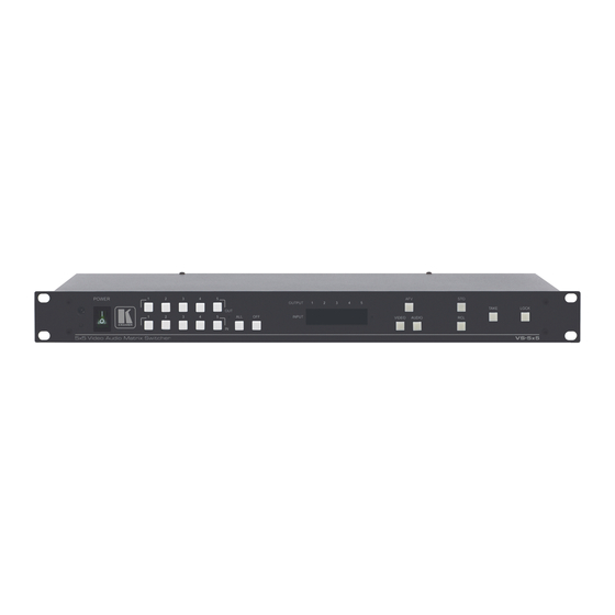
Figure 1: VS-5x5 Video Audio Matrix Switcher - Front Panel Feature Function IR Receiver The yellow LED is illuminated when receiving signals from the infrared remote control transmitter POWER Switch Illuminated switch for turning the unit ON or OFF OUT Buttons... -
Page 8: Figure 2: Vs-5X5 Video Audio Matrix Switcher - Rear Panel
Press to reset the unit to its original factory settings, or after firmware upgrade FLASH PROG Button Using a screwdriver if required, push in for “Program” to upgrade to the latest Kramer firmware or release for Normal (the factory default) RS-485 Terminal Block Port Pin G is for ground connection;... -
Page 9: Installing In A Rack
Installing in a Rack VS-5x5 - Installing in a Rack... -
Page 10: Connecting The Vs-5X5 5X5 Video Audio Matrix Switcher
To connect the VS-5x5, do the following: Switch OFF the power on each device before connecting it to your VS-5x5. After connecting your VS-5x5, switch on its power and then switch on the power on each device. DO NOT push in the rear panel Flash Program “Program”... -
Page 11: Connecting To The Vs-5X5 Via Rs-232
5. Connect the power cord. We recommend that you use only the power cord that is supplied with this machine Figure 3: Connecting the VS-5x5 5x5 Video Audio Matrix Switcher Connecting to the VS-5x5 via RS-232 You can connect to the unit via a crossed RS-232 connection, using for example, a PC. -
Page 12: Connecting A Pc Or Controller To The Rs-485 Port
Figure 5: Straight Cable RS-232 Connection with a Null Modem Adapter Connecting a PC or Controller to the RS-485 Port You can operate the VS-5x5 via the RS-485 port from a distance of up to 1200m (3900ft) using any device equipped with an RS-485 port (for example, a PC). For successful communication, you must set the RS-485 machine number and bus termination. -
Page 13: Connecting A Balanced/Unbalanced Stereo Audio Input/Output
OFF for External Vertical Interval Source (default) Source Section 11, instruction # 7 Reserved Reserved RS-485 ON for RS-485 line termination with 120Ω; Termination OFF for no RS-485 line termination VS-5x5 - Connecting the VS-5x5 5x5 Video Audio Matrix Switcher... -
Page 14: Setting The Machine
The MACHINE # determines the position of a VS-5x5 unit, specifying which VS-5x5 unit is being controlled when several VS-5x5 units connect to a PC or serial controller. Set the MACHINE # on a VS-5x5 unit via DIPS 1, 2, 3 and 4, according to the following table. -
Page 15: Controlling Via Rs-232 And Rs-485
Controlling via RS-232 and RS-485 You can cascade up to 8 VS-5x5 units with control from a PC or serial controller. To cascade up to 8 individual VS-5x5 units, via RS-232 and RS-485, do the following: 1. Connect the composite video sources and acceptors, as well as the appropriate stereo audio sources and acceptors, as Section 5.4... -
Page 16: Figure 10: Cascade Configuration For Rs-232/Rs-485 Control
Figure 10: Cascade Configuration for RS-232/RS-485 Control VS-5x5 - Controlling via RS-232 and RS-485... -
Page 17: Operating The Vs-5X5
PC, or other serial controller • RC-IR3 infrared remote control transmitter Displaying Unit Characteristics The VS-5x5 unit characteristics are displayed in the following circumstances: • Immediately (and automatically) after switching on the power; and • When simultaneously pressing the 3 “IN” buttons 1, 2 and 3, for 3 seconds The following information is displayed in the 7-segment display: •... -
Page 18: Choosing The Audio-Follow-Video Or Breakaway Option
7-segment display, relate to the video section Switching OUT-IN Combinations To switch a video/audio input to a video/audio output, do the following: 1. Press an OUT button (1, 2, 3, 4 or ALL). The 7-segment display flashes. VS-5x5 - Operating the VS-5x5... -
Page 19: Confirming Settings
Confirming Settings Choose to work in the AT ONCE or the CONFIRM mode. When the VS-5x5 operates in the AT ONCE mode (TAKE button is not lit), pressing an OUT-IN combination implements the switch immediately. In the CONFIRM mode (TAKE button is lit), the TAKE button must be pressed to authorize the switch. -
Page 20: Storing/Recalling Input/Output Configurations
Figure 12: Storing and Recalling using the Input / Output Buttons The gray numbers (1 to 10) in Figure 12 that illustrate the corresponding store/recall configuration numbers, are for the purpose of illustration only and do not appear on the buttons VS-5x5 - Operating the VS-5x5... - Page 21 The memory recalls the stored data from that reference. Tip: If you cannot remember which of the 10 input/output configurations is the one that you want, set the VS-5x5 to the CONFIRM mode and manually scan all the input/output configurations until you locate it.
-
Page 22: Locking The Front Panel
Locking the Front Panel To prevent changing the settings accidentally or tampering with the unit via the front panel buttons, lock your VS-5x5. Unlocking releases the protection mechanism. Nevertheless, even though the front panel is locked you can still operate via RS-232 or RS-485, as well as via... -
Page 23: Technical Specifications
19" x 7" x 1U (W, D, H) rack mountable WEIGHT: 2.7 kg (6 lbs.) approx. ACCESSORIES: Power cord, null-modem adapter, Windows®-based Kramer control software, RC-IR3 infrared remote control transmitter Specifications are subject to change without notice at http://www.kramerelectronics.com VS-5x5 - Technical Specifications... -
Page 24: Table Of Hex Codes For Serial Communication
This table lists the Hex values for switching via RS-232/RS-485 a single machine (MACHINE # 1): Switching Audio Channels Switching Video Channels IN 1 IN 2 IN 3 IN 4 IN 5 VS-5x5 - Table of Hex Codes for Serial Communication... -
Page 25: Tables Of Hex Codes For Audio Input/Output Gain Control
This command is sent once, and the “audio inputs gain adjustment” mode continues until instruction 42 changes to the “audio outputs gain adjustment” mode. The next table lists the Hex values for the audio gain control of the 5 inputs. VS-5x5 - Tables of Hex Codes for Audio Input/Output Gain Control... - Page 26 INPUTS VS-5x5 - Tables of Hex Codes for Audio Input/Output Gain Control...
-
Page 27: Tables Of Hex Codes For Audio Output Gain Control
The command is sent once, and the “audio outputs gain adjustment” mode continues until instruction 42 changes to the “audio inputs gain adjustment” mode. The next table lists the Hex values for the audio gain control of the 5 outputs. VS-5x5 - Tables of Hex Codes for Audio Input/Output Gain Control... - Page 28 OUTPUTS *In the Mute state, the audio output is physically disconnected from the input VS-5x5 - Tables of Hex Codes for Audio Input/Output Gain Control...
-
Page 29: Kramer Protocol 2000
Kramer Protocol 2000 The VS-5x5 is compatible with Kramer’s Protocol 2000 (version 0.5) (below). This RS-232 / RS-485 communication protocol uses four bytes of information as defined below. For RS-232, a null-modem connection between the machine and controller is used. The default data rate is 9600 baud, with no parity, 8 data bits and 1 stop bit. - Page 30 0 - Panel unlocked PANEL 1 - Panel locked REQUEST WHETHER PANEL IS LOCKED AUDIO PARAMETER INPUT Bit: 0 - Gain SETTINGS FOR I0 - 0=input; 1=output INSTRUCTIONS 22, I1 - Left 24, 25 I2 - Right VS-5x5 - Kramer Protocol 2000...
- Page 31 NOTE 8 - The reply to the "REQUEST WHETHER SETUP IS DEFINED" is as in TYPE 3 above, except that here the OUTPUT is assigned with the value 0 if the setup is not defined; or 1 if it is defined. VS-5x5 - Kramer Protocol 2000...
- Page 32 NOTE 18 – After this instruction is sent, the unit responds to the ASCII command set. The ASCII command to operate with the HEX command set must be sent in order to return to working with HEX codes. VS-5x5 - Kramer Protocol 2000...
- Page 33 NOTE 23 – Further information needed in instructions 21, 22, 25 and 26, is sent using instruction 42 – which is sent prior to the instruction. For example, to request the audio gain value of right input # 9, send hex codes and then send HEX codes VS-5x5 - Kramer Protocol 2000...
- Page 34 1. Any product which is not distributed by us or which is not purchased from an authorized Kramer dealer. If you are uncertain as to whether a dealer is authorized, please contact Kramer at one of the agents listed in the Web site www.kramerelectronics.com.
- Page 35 For the latest information on our products and a list of Kramer distributors, visit our Web site where updates to this user manual may be found. We welcome your questions, comments, and feedback. Web site: www.kramerelectronics.com E-mail: info@kramerel.com SAFETY WARNING...
Need help?
Do you have a question about the VS-5x5 and is the answer not in the manual?
Questions and answers