Table of Contents
Advertisement
Quick Links
Advertisement
Table of Contents

Related Manuals for Kramer VS-81HD


Summary of Contents for Kramer VS-81HD
- Page 1 Kramer Electronics, Ltd. USER MANUAL Model: VS-81HD 8x1 HD/SD-SDI Switcher...
-
Page 2: Table Of Contents
Kramer Protocol 2000 Figures Figure 1: VS-81HD 8x1 HD/SD-SDI Switcher Figure 2: Connecting the VS-81HD 8x1 HD/SD-SDI Switcher Figure 3: VS-81HD MACHINE ID Dipswitches Figure 4: Connecting a PC without using a Null-modem Adapter Figure 5: Controlling via RS-485 (for example, using an RC-3000) - Page 3 Tables Table 1: VS-81HD 8x1 HD/SD-SDI Switcher Features Table 2: MACHINE ID Dipswitch Settings Table 3: Technical Specifications of the VS-81HD 8x1 HD/SD-SDI Switcher Table 4: Protocol Definitions Table 5: Instruction Codes for Protocol 2000 Contents KRAMER: SIMPLE CREATIVE TECHNOLOGY...
-
Page 4: Introduction
GROUP 6: Accessories and Rack Adapters; GROUP 7: Scan Converters and Scalers; and GROUP 8: Cables and Connectors 2 Download up-to-date Kramer user manuals from the Internet at this URL: http://www.kramerelectronics.com 3 The complete list of Kramer cables is on our Web site at http://www.kramerelectronics.com Introduction... - Page 5 Getting Started KRAMER: SIMPLE CREATIVE TECHNOLOGY...
-
Page 6: Overview
Has an OFF button to disconnect the outputs Has a front panel lock button The VS-81HD, which is housed in a 19" 1U rack mountable enclosure, and is fed from a 100-240 VAC universal switching power supply, can be controlled via the:... -
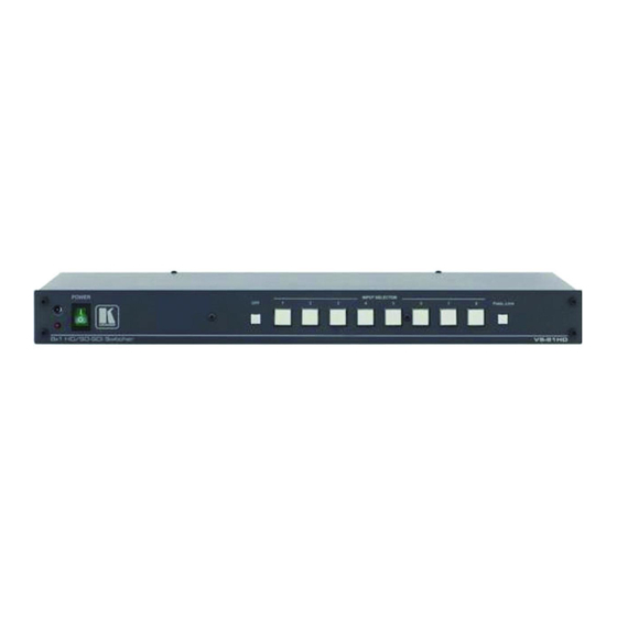
Page 7: Figure 1: Vs-81Hd 8X1 Hd/Sd-Sdi Switcher
Your VS-81HD 8x1 HD/SD-SDI Switcher Figure 1: VS-81HD 8x1 HD/SD-SDI Switcher KRAMER: SIMPLE CREATIVE TECHNOLOGY... -
Page 8: Table 1: Vs-81Hd 8X1 Hd/Sd-Sdi Switcher Features
Your VS-81HD 8x1 HD/SD-SDI Switcher Table 1: VS-81HD 8x1 HD/SD-SDI Switcher Features Feature IR Receiver POWER Switch OFF Button INPUT SELECTOR Buttons PANEL LOCK Button IN BNC Connector TERM Button LOOP BNC Connector INPUTS BNC Connectors OUTPUTS SDI BNC Connectors... -
Page 9: Using The Ir Transmitter
This distance can be extended to up to 60 meters when used with three extension cables Before using the external IR receiver, be sure to arrange for your Kramer dealer to insert the internal IR connection cable that fits into the REMOTE IR opening on the rear panel. -
Page 10: Installing On A Rack
Always mount the machine in the rack before you attach any cables or connect the machine to the power If you are using a Kramer rack adapter to situations where kit (for a machine that is not 19"), see the Rack Adapters user manual for... -
Page 11: Connecting Your Vs-81Hd 8X1 Hd/Sd-Sdi Switcher
7. Connect the power cord 1 Switch OFF the power on each device before connecting it to your VS-81HD. After connecting your VS-81HD, switch on its power and then switch on the power on each device 2 When only one output is required, connect that output, and leave the other output unconnected 3 Not illustrated in Figure 2 4 Push in to terminate the input. -
Page 12: Figure 2: Connecting The Vs-81Hd 8X1 Hd/Sd-Sdi Switcher
Connecting Your VS-81HD 8x1 HD/SD-SDI Switcher Figure 2: Connecting the VS-81HD 8x1 HD/SD-SDI Switcher... -
Page 13: Dipswitch Settings
The MACHINE ID determines the position of a VS-81HD unit, specifying which VS-81HD unit is being controlled when several VS-81HD units connect to a PC or serial controller. Set the Machine number on a VS-81HD unit via MACHINE ID DIPS 1, 2, 3 and 4, according to Table 2. -
Page 14: Controlling Via Rs-232 (For Example, Using A Pc)
To connect a PC to the VS-81HD unit, using the Null-modem adapter provided with the machine (recommended): Connect the RS-232 DB9 rear panel port on the VS-81HD unit to the Null-modem adapter and connect the Null-modem adapter with a 9-wire... -
Page 15: Controlling Via The Rs-485 Port
VS-81HD units. (If using shielded twisted pair cable, the shield is usually connected to the “G” (Ground) PIN of the first unit). 2. Set the first VS-81HD unit as MACHINE # 1 and the following seven VS-81HD units as MACHINE # 2 to MACHINE # 8, according to Table 2. -
Page 16: Controlling Via Ethernet
6.4.1 Connecting the ETHERNET Port directly to a PC (Crossover Cable) You can connect the Ethernet port of the VS-81HD to the Ethernet port on your PC, via a crossover cable with RJ-45 connectors. This type of connection is recommended for identification of the factory default... -
Page 17: Connecting The Ethernet Port Via A Network Hub (Straight-Through Cable)
Figure 7: Internet Protocol (TCP/IP) Properties Window 6.4.2 Connecting the ETHERNET Port via a Network Hub (Straight-Through Cable) You can connect the Ethernet port of the VS-81HD to the Ethernet port on a network hub or network router, via a straight-through cable with RJ-45 connectors. 6.4.3 Configuring the Ethernet Port After connecting the Ethernet port, you have to install and configure it. -
Page 18: Controlling Via The Remote Connector
Connecting Your VS-81HD 8x1 HD/SD-SDI Switcher 6.5 Controlling via the REMOTE Connector The dry contact remote control pins operate in a similar way to the input selector button. Using the contact closure remote control lets you route an input to the outputs by remote control. To do so, temporarily connect the required input (from 1 to 8) pin on the REMOTE terminal block connector to the GND (ground) pin. -
Page 19: Operating The Vs-81Hd
1 For details of how to route an input to an output using the REMOTE connector, see section 6.5 2 Nevertheless, even though the front panel is locked you can still operate via RS-232 or RS-485, as well as via the Kramer... -
Page 20: Technical Specifications
Universal, 100-240VAC, 50/60Hz 22VA DIMENSIONS: 19 inch (W), 7 inch (D), 1U (H) rack mountable WEIGHT: 1.5kg. (3.3lbs.) approx. ACCESSORIES: Power cord, Null-modem adapter 1 Specifications are subject to change without notice Technical Specifications of the VS-81HD 8x1 HD/SD-SDI Switcher... -
Page 21: Kramer Protocol 2000
Kramer Protocol 2000 The VS-81HD is compatible with Kramer’ s Protocol 2000 (version 0.50) (below). This RS-232/RS-485/Ethernet (app. level) communication protocol uses four bytes of information as defined below. For RS-232, a null-modem connection between the machine and controller is used. The default data rate is 9600 baud, with no parity, 8 data bits and 1 stop bit. -
Page 22: Table 5: Instruction Codes For Protocol 2000
This code is also returned to the PC if an RS-232 instruction is sent while the machine is being programmed via the front panel. Reception of this code by the switcher is not valid. Kramer Protocol 2000 , DEFINITION FOR SPECIFIC INSTRUCTION... -
Page 23: Kramer Protocol
NOTE 16 - The reply to the “REQUEST WHETHER PANEL IS LOCKED” is as in NOTE 4 above, except that here the OUTPUT is assigned with the value 0 if the panel is unlocked, or 1 if it is locked. Kramer Protocol 2000 , 81 (i.e. 128dec+ 22dec for 2nd byte, and 128dec+ 16dec for 3rd byte). - Page 24 EXCLUSION OF DAMAGES The liability of Kramer for any effective products is limited to the repair or replacement of the product at our option. Kramer shall not be liable for: 1. Damage to other property caused by defects in this product, damages based upon inconvenience, loss of use of the product, loss of time, commercial loss;...
- Page 25 For the latest information on our products and a list of Kramer distributors, visit our Web site: www.kramerelectronics.com, where updates to this user manual may be found. We welcome your questions, comments and feedback. Safety Warning: Disconnect the unit from the power supply before opening/servicing.
Need help?
Do you have a question about the VS-81HD and is the answer not in the manual?
Questions and answers