Kramer VS-1616D User Manual
16x16 digital matrix switcher
Hide thumbs
Also See for VS-1616D:
- User manual (165 pages) ,
- Installation instructions (2 pages) ,
- User manual (51 pages)
Table of Contents
Advertisement
Quick Links
Download this manual
See also:
User Manual
Advertisement
Table of Contents

Related Manuals for Kramer VS-1616D


Summary of Contents for Kramer VS-1616D
- Page 1 Kramer Electronics, Ltd. USER MANUAL Model: VS-1616D 16x16 Digital Matrix Switcher...
-
Page 2: Table Of Contents
Safety Instructions Shielded Twisted Pair/Unshielded Twisted Pair About the Power Connect™ Feature Recycling Kramer Products Defining the VS-1616D 16x16 Digital Matrix Switcher Using the IR Transmitter Installing the VS-1616D in a Rack Connecting the VS-1616D 16x16 Digital Matrix Switcher Port Numbering 6.1.1... - Page 3 10.4.1 Testing the Projector Output 10.4.2 Testing the Output Signal Path to the Projector 10.4.3 Testing the Input and Output Signal Path to the Projector I/O Card Hardware Installation Instructions Upgrading the VS-1616D Firmware Technical Specifications Default Communication Parameters Factory Default EDID 15.1...
- Page 4 Figures Figure 1: VS-1616D 16x16 Digital Matrix Switcher Front Panel Figure 2: VS-1616D Front Panel Numeric Keypad Figure 3: VS-1616D 16x16 Digital Matrix Switcher Rear Panel Showing DVI cards Figure 4: Connecting the VS-1616D Figure 5: Sample Port Numbering Figure 6: EDID Numbering Assignment...
-
Page 5: Introduction
Introduction Introduction Welcome to Kramer Electronics! Since 1981, Kramer Electronics has been providing a world of unique, creative, and affordable solutions to the vast range of problems that confront the video, audio, presentation, and broadcasting professional on a daily basis. In recent years, we have redesigned and upgraded... -
Page 6: Getting Started
• Unpack the equipment carefully and save the original box and packaging materials for possible future shipment • Review the contents of this user manual 2.1 Quick Start The following quick start chart summarizes the basic setup and operation steps. KRAMER: SIMPLE CREATIVE TECHNOLOGY... - Page 7 Getting Started...
-
Page 8: Overview
Section 13 3 The VS-1616D is a sophisticated device but has been designed to be as simple as possible to operate. Due to space limitations on the front panel 32 input/output selector buttons are instead substituted by a keypad. For details of how to route inputs to outputs, see Section 7.2... -
Page 9: Recommendations For Best Performance
(often associated with low quality cables) • Avoid interference from neighboring electrical appliances that may adversely influence signal quality and position your Kramer VS-1616D in a location free from moisture and away from excessive sunlight and dust 3.1 Recommendations for Best Performance To achieve the best performance: •... -
Page 10: About The Power Connect™ Feature
Defining the VS-1616D 16x16 Digital Matrix Switcher 3.2 About the Power Connect™ Feature The Power Connect™ feature here means that the VS-1616D can supply power to the TP transmitters and receivers (for example, the PT-573 and PT-574) as long as the devices are within 90m (270ft) of each other. -
Page 11: Figure 1: Vs-1616D 16X16 Digital Matrix Switcher Front Panel
Defining the VS-1616D 16x16 Digital Matrix Switcher Figure 1: VS-1616D 16x16 Digital Matrix Switcher Front Panel Note: Buttons 14, 15 and 16 function as the TAKE, MENU and LOCK buttons respectively... -
Page 12: Figure 2: Vs-1616D Front Panel Numeric Keypad
Defining the VS-1616D 16x16 Digital Matrix Switcher Table 1: VS-1616D 16x16 Digital Matrix Switcher Front Panel Features Feature Function Press to exit the current operation EDID Press to assign EDID channels Press to store the current setup in a preset... -
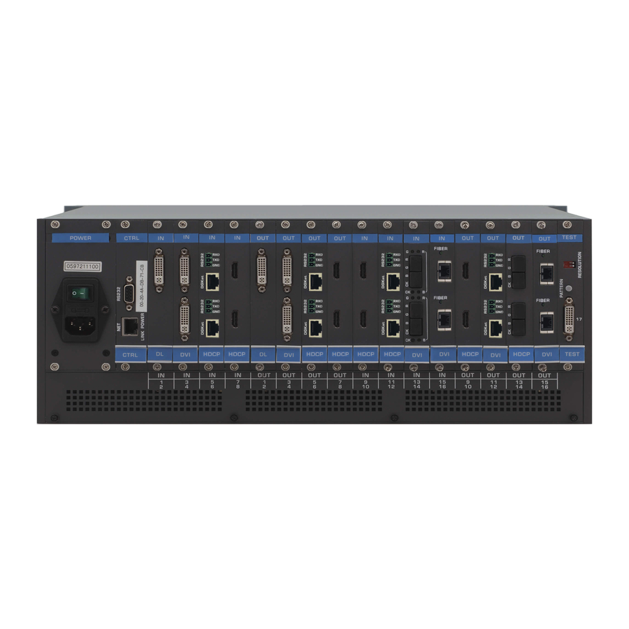
Page 13: Figure 3: Vs-1616D 16X16 Digital Matrix Switcher Rear Panel Showing Dvi Cards
Defining the VS-1616D 16x16 Digital Matrix Switcher Figure 3 Table 3 define the rear panel of the VS-1616D showing DVI cards installed as an example. Figure 3: VS-1616D 16x16 Digital Matrix Switcher Rear Panel Showing DVI cards... -
Page 14: Using The Ir Transmitter
Defining the VS-1616D 16x16 Digital Matrix Switcher Table 3: VS-1616D 16x16 Digital Matrix Switcher Rear Panel Features Feature Function AC Mains Power Module Fuse holder and power cord socket. Connect to the AC mains supply RS-232 9-pin D-sub Port Connects to the remote operation PC or remote controller (see Section 6.4... -
Page 15: Installing The Vs-1616D In A Rack
Installing the VS-1616D in a Rack Installing the VS-1616D in a Rack This section provides instruction on rack mounting the VS-1616D. -
Page 16: Connecting The Vs-1616D 16X16 Digital Matrix Switcher
3. If required, connect a PC or remote controller to the RS-232 port (see Section 6.4) and/or the Ethernet port (see Section 1 Switch off the power for each device before connecting it to your VS-1616D 2 In this example only two inputs and two outputs are connected KRAMER: SIMPLE CREATIVE TECHNOLOGY... -
Page 17: Port Numbering
5. If necessary, review and set the system configuration using the Menu (see Section 8 Note: Given an input signal that is HDCP encoded, the VS-1616D will output a signal only if the output port to which it is switched supports HDCP. -
Page 18: Edid Numbering Examples
From IN 8 None (error message displayed) Note: AV data flow is: source > VS-1616D > display. EDID information flow is: display > VS-1616D > source, which means that the EDID input is the display side and the EDID output is the AV source side. This is the reverse of the AV data flow direction. -
Page 19: Audio Mode Selection On Hdmi Plus Audio Cards
Source (default) Only the DVI uses the analog (external) audio 6.4 Connecting to the VS-1616D via RS-232 You can connect to the VS-1616D via an RS-232 connection using, for example, a PC. Note that a null-modem adapter/connection is not required. -
Page 20: Connecting To The Vs-1616D Via Ethernet
To connect to the VS-1616D via RS-232: • Connect the RS-232 9-pin D-sub rear panel port on the VS-1616D unit via a 9-wire straight cable (only pin 2 to pin 2, pin 3 to pin 3, and pin 5 to pin 5 need to be connected) to the RS-232 9-pin D-sub port on your PC 6.5 Connecting to the VS-1616D via Ethernet... -
Page 21: Figure 9: Local Area Connection Properties Window
Connecting the VS-1616D 16x16 Digital Matrix Switcher Figure 9: Local Area Connection Properties Window 6. Select Use the following IP Address and enter the details as shown in Figure 10. You can use any IP address in the range 192.168.1.1 to 192.168.1.255 (excluding 192.168.1.39) that is provided by your IT... -
Page 22: Connecting To The Ethernet Port Via A Network Switch/Hub
7. Click OK. 6.5.2 Connecting to the Ethernet Port via a Network Switch/Hub To connect to the Ethernet port on the VS-1616D via a network switch/hub: • Connect the PC to the Ethernet network switch/hub using a straight through cable... -
Page 23: Operating Your Video Matrix Switcher
Figure 11: Default Startup Status Display Sequence The VS-1616D does not have separate output and input buttons. Instead, the front panel includes a numeric keypad within the Selector Buttons area . This numeric keypad lets you enter both the output and input numbers as well as various numeric configuration values (see Section 7.2... -
Page 24: Viewing The Display
7.2 Using the Selector Buttons For numbers between 1 and 9, the VS-1616D can handle two digit numbers as well as single digit numbers. When entering a single digit number (for example 5), you can either press 0 followed by 5, or 5 followed by ENT. -
Page 25: Toggling Between The At Once And Confirm Modes
Operating Your Video Matrix Switcher • Pressing an OUT-IN combination implements the switch without further user confirmation • You save time as execution is immediate and actions require no user confirmation • No protection is offered to correct an erroneous action In the Confirm mode: •... -
Page 26: Switching One Input To One Output
The inputs switch to the respective outputs as shown on the LCD display and the TAKE LED is lit. 1 In this example, input 9 is set to switch to output 6 and input 5 is set to switch to output 7 KRAMER: SIMPLE CREATIVE TECHNOLOGY... -
Page 27: Turning An Output Off
Operating Your Video Matrix Switcher 7.4.3 Turning an Output Off Turning an output off means that there is no input switched to this output. This is indicated on the display by the Input being blank underneath the relevant Output. To turn an output off: 1. -
Page 28: Locking The Front Panel Buttons
The front panel buttons are unlocked Using the Configuration Menus The configuration menus let you configure the VS-1616D to best suit your needs. There are two configuration menus: • Setup Menu—those that are accessed on a regular basis (for example, storing setups and setting the delay), see Section 8.1... -
Page 29: Figure 12: Menu Tree
Using the Configuration Menus Figure 12: Menu Tree The following rules apply to the menu operation: • If no selection is made within approximately 15 seconds, the operation times-out and the display reverts to the output/input display • At any point in the Menu, press ESC to move up one level or press BREAKAWAY to exit the Menu altogether •... -
Page 30: Using The Setup Menu
3. Using the numeric keys, enter the output to be turned off. The TAKE button flashes. 4. Press TAKE. The selected output is turned off. The display reverts to the output/input display showing that the selected output is turned off with the input being blank. KRAMER: SIMPLE CREATIVE TECHNOLOGY... -
Page 31: Setup Menu-7: Edid, Assignment To An Input
8.1.3 Setup Menu—7: EDID, Assignment to an Input This option assigns an EDID to between one and eight inputs in non-volatile storage. More than eight EDID assignments must be assigned in multiple batches. Each input on the VS-1616D has a factory default EDID loaded (see Section 15). -
Page 32: Setup Menu-9: Delay, Setting For An Output
3. Using the numeric keys, enter the preset (1 to 59) in which to store the current setup. The following is displayed: Wait ….. After a few seconds, if the preset is not empty, the following is displayed: SETUP NOT EMPTY CONFIRM KRAMER: SIMPLE CREATIVE TECHNOLOGY... -
Page 33: Setup Menu-6: Recall Setup Xx, Recalling A Preset
• Interface configuration (see Section 8.2.5 • Interface reply configuration ( Section 8.2.6 • Protocol switching ( Section 8.2.7 • Storing the default setup ( Section 8.2.8 • Resetting the VS-1616D ( Section 8.2.9 • Firmware revision display ( Section 8.2.10... -
Page 34: Config Menu-Input Signal Detection Display
Press BREAKAWAY to exit the Config Menu Wait approximately 15 seconds for the operation to time out Press MENU to move to the next Config Menu option 1 The LCD display shows the current status of the selected menu item KRAMER: SIMPLE CREATIVE TECHNOLOGY... -
Page 35: Config Menu-Input Port Parameter Setting
Using the Configuration Menus 8.2.2 Config Menu—Input Port Parameter Setting This option sets input port specific parameters. Ports that show an X have no parameters available to modify. Ports that show a 0 have parameters available to modify. The parameters that are available, such as, audio balance, depend on the type of card installed and whether the card is an input or an output card. - Page 36 3.5mm mini jack AUD-Embedded: HDMI audio is selected AUD-Ex-Digital: S/PDIF audio is selected (only works on HDMI plus S/PDIF card) AUD-Ex-Analog: Analog audio from the 3.5mm mini jack is selected (only works on HDMI plus analog audio card) KRAMER: SIMPLE CREATIVE TECHNOLOGY...
-
Page 37: Config Menu-Output Load Detection Display
Using the Configuration Menus VGA Input Card Parameter Description Default 1.DE (Auto, Manual, Do-Auto) Auto 2.Phase (Manual, Do-Auto) Manual 20.Brightness (0–63) 21.Contrast (0–63) 22.Hue (0–63) 23.Saturation (0–63) 30.Phase adjustment (0–255) 36. Reset SubBoard Re-power: power cycle the port Re-power Factory: perform a factory reset to default values of the port 42.Video Format (VGA, RGBHV, RGsB, RGBS, YUV) 64.Hor-Total Pixels... -
Page 38: Config Menu-Output Port Parameter Setting
10. Repeat from Step 6 to modify other parameters 11. Do one of the following: Press BREAKAWAY to exit the Config Menu Wait approximately 15 seconds for the operation to time out Press MENU to exit to the parameter list KRAMER: SIMPLE CREATIVE TECHNOLOGY... - Page 39 Using the Configuration Menus The following tables list the output port types and their relevant parameters HDMI plus Analog Audio Output Card Parameter Description Options 36.Reset SubBoard Re-power: power cycle the port Re-power Factory default: perform a factory reset to default values of the port 81.Volume Sets the audio output volume (0–100) 84.Audio Balance...
-
Page 40: Config Menu-Interface Configuration
2. Press MENU until the following is displayed: interface REPLY configuration current interface REPLY – ON This indicates the current Reply configuration status. 3. Press ENT to enter the Reply Submenu. The following is displayed: interface REPLY configuration 1:turn REPLY ON 2:never REPLY KRAMER: SIMPLE CREATIVE TECHNOLOGY... -
Page 41: Config Menu-Protocol Switching
A message is displayed indicating the new status of the Reply configuration. After a few seconds the next option on the Config Menu is displayed. 8.2.7 Config Menu—Protocol Switching The VS-1616D supports Kramer Protocol 3000 and Protocol 2000. To switch from Protocol 3000 (default) to Protocol 2000: 1. Press MENU twice. -
Page 42: Config Menu-Total Matrix Reset
Once more TAKE to confirm 6. Press TAKE. The following is displayed: Matrix erased!!! Please, wait … The matrix and device configuration are erased. After a few seconds the next option on the Config Menu is displayed. KRAMER: SIMPLE CREATIVE TECHNOLOGY... -
Page 43: Config Menu-Display Firmware Versions
Configuring the Number of Installed Input and Output Ports After installing or removing a module you need to set the number of input and output ports so that the VS-1616D recognizes the new configuration. Refer to Section 6.1 for an explanation of port numbering before setting the number of input and output ports. -
Page 44: Installing And Using The Test Module To Troubleshoot Video Problems
10 Installing and Using the Test Module to Troubleshoot Video Problems The VS-1616D includes a test module which can act as a video signal generator and can be used to diagnose video issues in an operating environment. The test module must be installed in the configuration before it can be used. When installing the test module, the number of configured inputs and outputs must be increased by one. -
Page 45: Setting The Pattern Of The Generated Video
The test module may be used in various ways to isolate video problems. The following examples are based on the signal paths shown in Figure 14 and a VS-1616D device installed as follows: • 16 inputs and 16 outputs • The test module is installed and configured (see Section 10.1 •... -
Page 46: Testing The Projector Output
2. Connect Output 1 to the projector. 3. Set the generated video resolution (see Section 10.2 4. Set the pattern for the generated video (see Section 10.3 5. Verify that the projector output is as expected. KRAMER: SIMPLE CREATIVE TECHNOLOGY... -
Page 47: Testing The Input And Output Signal Path To The Projector
7. Verify that the projector output is as expected. 11 I/O Card Hardware Installation Instructions The VS-1616D I/O cards mount in one of the 16 slots on the rear of the VS-1616D chassis. Slots are numbered from left to right and must be filled consecutively from left to right, without leaving empty slots. -
Page 48: Upgrading The Vs-1616D Firmware
8. Using a Phillips screwdriver, tighten the retaining screws at the top and bottom of the card to secure it to the chassis. 9. Power on the VS-1616D and follow the procedure to configure the new card (see Section 9 10. -
Page 49: Technical Specifications
Technical Specifications 13 Technical Specifications Table 9 lists the technical specifications of the VS-1616D. Table 9: Technical Specifications of the 16x16 Digital Matrix Switcher BANDWIDTH: Supports up to 3.2Gbps bandwidth per channel (limited by the card installed) MAX RESOLUTION: Up to UXGA; 1080p, 1920x1200... -
Page 50: Table 10: Technical Specifications Of Vs-1616D Compatible Cards
2 VGA on 15-pin HD connectors 1 Multi-mode glass fiber cables with LC connections must be used, such as the Kramer C-4LC/4LC 2 Multi-mode glass fiber cables with SC connections must be used, such as the Kramer C-SC/SC/OM3 3 Twisted pair cables with RJ-45 connections must be used, such as the Kramer BC-DGKat623... -
Page 51: Default Communication Parameters
Default Communication Parameters 14 Default Communication Parameters Table 11 lists the default communication parameters for the VS-1616D. Table 11: Default Communication Parameters for the VS-1616D EDID EDID data is passed between Output 1 and Input 1 RS-232 Protocol 2000/3000 Baud Rate:... -
Page 52: Hdcp Input Card
Green chromaticity..Gx 0.286 - Gy 0.610 Blue chromaticity..Bx 0.146 - By 0.069 White point (default)..Wx 0.284 - Wy 0.293 Additional descriptors... None Timing characteristics Horizontal scan range..31-94kHz Vertical scan range..50-85Hz Video bandwidth..170MHz CVT standard..... Not supported KRAMER: SIMPLE CREATIVE TECHNOLOGY... - Page 53 Factory Default EDID GTF standard..... Not supported Additional descriptors... None Preferred timing..Yes Native/preferred timing.. 1920x1080p at 60Hz (16:9) Modeline...."1920x1080" 148.500 1920 2008 2052 2200 1080 1084 1089 1125 +hsync +vsync Detailed timing #1..1920x1200p at 60Hz (16:10) Modeline...."1920x1200" 154.000 1920 1968 2000 2080 1200 1203 1209 1235 +hsync -vsync Standard timings supported 720 x 400p at 70Hz - IBM VGA 720 x 400p at 88Hz - IBM XGA2...
-
Page 54: Hdmi Input Card
640 x 480p at 72Hz - VESA 640 x 480p at 75Hz - VESA 800 x 600p at 56Hz - VESA 800 x 600p at 60Hz - VESA 800 x 600p at 72Hz - VESA 800 x 600p at 75Hz - VESA KRAMER: SIMPLE CREATIVE TECHNOLOGY... - Page 55 Factory Default EDID 832 x 624p at 75Hz - Apple Mac II 1024 x 768i at 87Hz - IBM 1024 x 768p at 60Hz - VESA 1024 x 768p at 70Hz - VESA 1024 x 768p at 75Hz - VESA 1280 x 1024p at 75Hz - VESA 1152 x 870p at 75Hz - Apple Mac II 1360 x 765p at 60Hz - VESA STD...
-
Page 56: Hdmi Plus Audio Input Card
1280 x 960p at 60Hz - VESA STD 1280 x 1024p at 60Hz - VESA STD 1400 x 1050p at 60Hz - VESA STD 1680 x 1050p at 60Hz - VESA STD 1600 x 1200p at 60Hz - VESA STD KRAMER: SIMPLE CREATIVE TECHNOLOGY... -
Page 57: Dvi Dual Channel Input Card
Factory Default EDID EIA/CEA-861 Information Revision number..3 IT underscan..... Not supported Basic audio....Supported YCbCr 4:4:4....Not supported YCbCr 4:2:2....Not supported Native formats... 1 Detailed timing #1..720x480p at 60Hz (4:3) Modeline...."720x480" 27.000 720 736 798 858 480 489 495 525 -hsync -vsync Detailed timing #2.. - Page 58 Detailed timing #4..1280x720p at 60Hz (16:9) Modeline...."1280x720" 74.250 1280 1390 1430 1650 720 725 730 750 +hsync +vsync Detailed timing #5..1280x720p at 50Hz (16:9) Modeline...."1280x720" 74.250 1280 1720 1760 1980 720 725 730 750 +hsync +vsync KRAMER: SIMPLE CREATIVE TECHNOLOGY...
-
Page 59: Dgkat Input Card
Factory Default EDID CE video identifiers (VICs) - timing/formats supported 720 x 576p at 50Hz - EDTV (4:3, 16:15) 1280 x 720p at 50Hz - HDTV (16:9, 1:1) 1920 x 1080i at 60Hz - HDTV (16:9, 1:1) 1920 x 1080i at 50Hz - HDTV (16:9, 1:1) 1280 x 720p at 60Hz - HDTV (16:9, 1:1) [Native] 1920 x 1080p at 60Hz - HDTV (16:9, 1:1) 1920 x 1080p at 50Hz - HDTV (16:9, 1:1) - Page 60 NB: NTSC refresh rate = (Hz*1000)/1001 CE audio data (formats supported) LPCM 3-channel, 24-bits at 44/48 kHz CE speaker allocation data Channel configuration..3.0 Front left/right..Yes Front LFE....No Front center..... Yes Rear left/right..No KRAMER: SIMPLE CREATIVE TECHNOLOGY...
-
Page 61: Hdbaset Input Card
Factory Default EDID Rear center....No Front left/right center.. No Rear left/right center... No Rear LFE....No CE vendor specific data (VSDB) IEEE registration number. 0x000C03 CEC physical address..1.0.0.0 Maximum TMDS clock..165MHz Raw data 00,FF,FF,FF,FF,FF,FF,00,2E,4D,00,02,01,00,00,00,0C,10,01,03,81,46,27,78,0A,D5,7C,A3,57,49,9C,25, 11,48,4B,FF,FF,80,8B,C0,81,00,95,00,81,40,81,80,90,40,B3,00,A9,40,0E,1F,00,80,51,00,1E,30,40,80, 37,00,6F,13,11,00,00,1E,28,3C,80,A0,70,B0,23,40,30,20,36,00,06,44,21,00,00,1A,00,00,00,FC,00,56, 53,2D,31,36,68,43,61,74,35,65,0A,20,00,00,00,FD,00,32,55,1F,5E,11,00,0A,20,20,20,20,20,20,01,92, 02,03,1A,41,47,11,13,05,14,84,10,1F,23,0A,06,04,83,05,00,00,65,03,0C,00,10,00,8C,0A,D0,8A,20,E0, 2D,10,10,3E,96,00,58,C2,21,00,00,18,01,1D,80,18,71,1C,16,20,58,2C,25,00,C4,8E,21,00,00,9E,01,1D, 80,D0,72,1C,16,20,10,2C,25,80,C4,8E,21,00,00,9E,01,1D,00,72,51,D0,1E,20,6E,28,55,00,C4,8E,21,00,... - Page 62 CE vendor specific data (VSDB) IEEE registration number. 0x000C03 CEC physical address..1.0.0.0 Maximum TMDS clock..165MHz Report information Date generated... 14/07/2013 Software revision..2.60.0.972 Data source....File Operating system..6.1.7601.2.Service Pack 1 Raw data 00,FF,FF,FF,FF,FF,FF,00,2E,4D,00,02,01,00,00,00,0C,10,01,03,81,46,27,78,0A,D5,7C,A3,57,49,9C,25, 11,48,4B,FF,FF,80,8B,C0,81,00,95,00,81,40,81,80,90,40,B3,00,A9,40,01,1D,00,72,51,D0,1A,20,6E,28, KRAMER: SIMPLE CREATIVE TECHNOLOGY...
-
Page 63: Vga Input Card
Factory Default EDID 55,00,7E,88,42,00,00,1A,28,3C,80,A0,70,B0,23,40,30,20,36,00,06,44,21,00,00,1A,00,00,00,FC,00,56, 53,2D,31,36,48,44,42,53,54,0A,20,20,00,00,00,FD,00,32,55,1F,5E,11,00,0A,20,20,20,20,20,20,01,D3, 02,03,1A,71,47,11,13,05,14,84,10,1F,23,0A,06,04,83,05,00,00,65,03,0C,00,10,00,8C,0A,D0,8A,20,E0, 2D,10,10,3E,96,00,58,C2,21,00,00,18,01,1D,80,18,71,1C,16,20,58,2C,25,00,C4,8E,21,00,00,9E,01,1D, 80,D0,72,1C,16,20,10,2C,25,80,C4,8E,21,00,00,9E,01,1D,00,72,51,D0,1E,20,6E,28,55,00,C4,8E,21,00, 00,1E,01,1D,00,BC,52,D0,1E,20,B8,28,55,40,C4,8E,21,00,00,1E,00,00,00,00,00,00,00,00,00,00,00,90 15.8 VGA Input Card Monitor Model name....VGA-IN2-F16 Manufacturer..... KRM Plug and Play ID..KRM040B Serial number.... 17056 Manufacture date..2011, ISO week 48 Filter driver.... None ------------------------- EDID revision.... 1.3 Input signal type.. -
Page 64: Communication Protocols
11,48,4B,FF,FF,80,31,40,45,40,61,40,71,4F,81,8F,81,40,81,80,8B,C0,D6,09,80,A0,20,E0,2D,10,10,60, A2,00,04,03,00,00,00,18,02,3A,80,18,71,38,2D,40,58,2C,45,00,10,09,00,00,00,1E,00,00,00,FC,00,56, 47,41,2D,49,4E,32,2D,46,31,36,0A,20,48,3F,40,30,62,B0,32,40,40,C0,13,00,6F,13,11,00,00,1E,00,0C 16 Communication Protocols 16.1 Protocol 3000 The VS-1616D can be operated using serial commands from a PC, remote controller or touch screen using the Kramer Protocol 3000. This section describes the: • Kramer Protocol 3000 syntax (see Section 16.1.1... -
Page 65: Command Terms
You can directly enter all commands using a terminal with ASCII communications software, such as HyperTerminal, Hercules, etc. Connect the terminal to the serial or Ethernet port on the Kramer device. To enter CR press the Enter key. ( LF is also sent but is ignored by command parser). -
Page 66: Command Forms
Communication Protocols For commands sent from some non-Kramer controllers like Crestron, some characters require special coding (such as, /X##). Refer to the controller manual. 16.1.5 Command Forms Some commands have short name syntax in addition to long name syntax to allow faster typing. -
Page 67: Protocol 2000
Communication Protocols Short Command Description Permission Form PROT-VER? Read device protocol version Common PRST-LST? PLST? Read saved presets list Switch PRST-RCL PRCL Recall saved preset Switch PRST-STO PSTO Store current connections to preset Switch PRST-VID? PVID? Read video connections from saved preset Switch RESET Reset device... - Page 68 Communication Protocols IN 8 IN 9 IN 10 IN 11 IN 12 IN 13 IN 14 IN 15 IN 16 KRAMER: SIMPLE CREATIVE TECHNOLOGY...
- Page 70 For the latest information on our products and a list of Kramer distributors visit www.kramerelectronics.com where updates to this user manual may be found. We welcome your questions, comments and feedback. Safety Warning: Disconnect the unit from the power supply before opening/servicing.
Need help?
Do you have a question about the VS-1616D and is the answer not in the manual?
Questions and answers