ACTi ACM-5611 Hardware User Manual
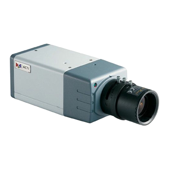
Megapixel ip ir d/n poe box camera
Hide thumbs
Also See for ACM-5611:
- Specifications (2 pages) ,
- Quick installation manual for compact flash 1gb/2gb (10 pages)
Advertisement
Advertisement
Table of Contents

Related Manuals for ACTi ACM-5611


Summary of Contents for ACTi ACM-5611
- Page 1 Megapixel IP IR D/N PoE Box Camera ACM-5611 Ver. 120312 Hardware User’s Manual...
-
Page 3: Trademarks
PRECAUTIONS Read these instructions All the safety and operating instructions should be read before the product is operated. Heed all warnings All warnings on the product and in the instruction manual should be adhered to. The symbol indicates the following items, please carefully read the description next to each symbol. - Page 4 and can radiate radio frequency energy and, if not installed and used in accordance with the instruction manual, may cause harmful interference to radio communications. Operation of this equipment in a residential area is likely to cause harmful interference in which case the user will be required to correct the interference at his own expense.
-
Page 5: Table Of Contents
Table of Contents PRECAUTIONS________________________________________________ 0-1 Trademarks ________________________________________________________________ 0-1 Liability ___________________________________________________________________ 0-1 FCC/CE Regulation __________________________________________________________ 0-1 INTRODUCTION ______________________________________________ 1-1 Package Contents _______________________________________________ 1-1 Features and Benefits ____________________________________________ 1-2 Safety Instructions ______________________________________________ 1-4 Physical Description _____________________________________________ 1-6 Basic Connections _______________________________________________ 1-9 Product Specification ___________________________________________ 1-10... -
Page 7: Introduction
INTRODUCTION 1.1 Package Contents ACM-5611 Product CD Terminal Blocks for Power & DI/O Warranty Card Accessory *For the mounting block, please attach it flat side to the front. There are two types of mounting blocks, and this device uses the white version. Please do not use the black verison. -
Page 8: Features And Benefits
1.2 Features and Benefits This IP device is a cutting-edge digital video transmission device. It can compress and transmit real time images with outstanding images quality (SXGA, 1280x1024) at reasonable bandwidth through a standard TCP/IP network. That is because it is Ethernet ready and has the powerful ARM9 SoC with excellent system performance to offer dual streams of MPEG4/MJPEG, and both formats offer megapixel resolution. - Page 9 powerful surveillance program is included in the package and is very free to use. Users can easily utilize the existing PC to be a digital video recorder. Schedule recording and manual recording keep every important image recorded in the local hard disk. Reliable and accurate motion detection with instant warning makes you responsive in every condition.
-
Page 10: Safety Instructions
1.3 Safety Instructions Don’t use the power supply with other voltages This device is likely to be damaged or damage other equipments / personnel, if you use a power supply with different voltage than the one included with this device. All warranty of this product will be voided in the situations above. - Page 11 If the video product does not operate normally by following the operating Instructions in this manual. Adjust only those controls that are covered by the instruction manual as an improper adjustment . Other controls may result in damage and will often require extensive work by a qualified technician to restore the video product to its normal operation.
-
Page 12: Physical Description
1.4 Physical Description Ethernet Port The IP device connects to the Ethernet via a standard RJ45 connector. Supporting NWAY, this IP device can auto detect the speed of local network segment (10Base-T/100Base-TX Ethernet). Reset Button Step 1: Switch off IP device by disconnecting the power cable Step 2: Press and continue to hold the Reset Button. - Page 13 provides the interface to: •1 transistor output - For connecting external devices such as relays and LED:s. Connected devices can be activated by Output buttons on the Live View page or by an Event Type. The output will show as active (in Event Configuration >...
-
Page 14: Power Input
connector (also green) on the camera. 3.3V FUSE 1A DC TO DC CONVERTER POWER INPUT EARTH GND DC POWER RELAY DEVICE DIODE CAMERA Power Input If your power input is DC12V. -
Page 15: Basic Connections
1.5 Basic Connections Follow the procedures below to connect the IP device to the respective apparatuses. 1. Connect the power adaptor to IP device 2. Connect IP device’s ethernet port to an Ethernet (RJ45 connectors). If your IP device has PoE built-in, you can regard it as a PD and connect it directly to a PSE device like PoE switch. -
Page 16: Product Specification
1.6 Product Specification 1-10...
Need help?
Do you have a question about the ACM-5611 and is the answer not in the manual?
Questions and answers