
Related Manuals for Lorex LH400 LINK SERIES


Summary of Contents for Lorex LH400 LINK SERIES
-
Page 1: User Manual
LOREX Link H.264, INTERNET REMOTE VIEWING, LIGHT TOUCH DIGITAL VIDEO SURVEILLANCE RECORDER USER MANUAL English Version 2.0 MODEL: LH400 LINK SERIES www.lorextechnology.com © Copyright 2010 Lorex Technology Inc. - Page 2 Thank you for purchasing this product. Lorex is committed to providing our customers with a high quality, reliable security solution. This manual refers to the following model(s): • LH400 Series (4/8/16 channel configurations) For more information on this product, firmware updates, and accessory products, please visit us at: www.lorextechnology.com...
-
Page 3: Important Safeguards
Important Safeguards In addition to the careful attention devoted to quality standards in the manufacturing process of your video product, safety is a major factor in the design of every instrument. However, safety is your responsibility too. This sheet lists important information that will help to assure your enjoyment and proper use of the video product and accessory equipment. -
Page 4: General Precautions
Service 13. Servicing - Do not attempt to service this video 19. Cleaning - Unplug the video product from the wall equipment yourself as opening or removing covers outlet before cleaning. Do not use liquid cleaners or may expose you to dangerous voltage or other aerosol cleaners. - Page 5 General Precautions 1. All warnings and instructions in this manual should be followed. 2. Remove the plug from the outlet before cleaning. Do not use liquid aerosol detergents. Use a water dampened cloth for cleaning. 3. Do not use this unit in humid or wet places. 4.
- Page 6 • Internet Remote Functions****: View, Search &Playback, Back-up and Setup • Apple MAC compatible** - single channel live viewing using the Safari web browser • Lorex DDNS (Dynamic Domain Name System) service keeps you connected anywhere at all times • E-mail alerts keeps you informed when events occur (DDNS registration required) * Instant mobile viewing using Blackberry™, iPhone™...
-
Page 7: Table Of Contents
TABLE OF CONTENTS Getting Started ..........1 Basic Setup . - Page 8 Installing Lorex Client 8.0 ........
- Page 9 Health ..............46 Clearing Health Status .
- Page 10 Advanced Search ..............89 Appendix M: Lorex Easy Connect Internet Remote Viewing ... 90 What is Easy Connect? .
-
Page 11: Getting Started
GETTING STARTED The system comes with the following components: LOREX LINK DIGITAL VIDEO RECORDER POWER SUPPLY REMOTE CONTROL MOUSE OCTOPUS CABLE ETHERNET CABLE INSTRUCTION MANUAL, [16-CHANNEL ONLY] QUICKSTART GUIDE, & SOFTWARE CD HARD DRIVE SIZE, NUMBER OF CHANNELS, AND CAMERA CONFIGURATION MAY VARY BY MODEL. -
Page 12: Basic Setup
BASIC SETUP 1. Connect the cameras a. Connect BNC cameras to the BNC ports on the rear panel (4/8-channel models). a. 16-CHANNEL MODELS ONLY: Connect the single end of the octopus cable to the VIDEO IN1-16 port Figure 1.0 Connect BNC cameras to the system (see figure 1.1). -
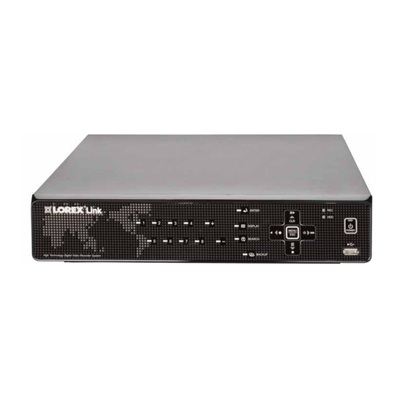
Page 13: Front Panel
FRONT PANEL Figure 1.5 Front panel (8-channel model shown) 1. Channel buttons: Press to view channels individually in full-screen. : Press to increase values in menu options. : Press to switch between full-screen single channel, quad, and split-screen display views. : Press to confirm menu options. - Page 14 Front Panel Front Panel (cont’d.) Figure 1.6 Front panel (8-channel model shown) : Press to perform the following: Live viewing • : Open the Log menu • Playback : Stop playback : Press to perform the following: Live viewing • : Start/stop scheduled recording (Recording Schedule must already be configured;...
-
Page 15: Rear Panel
REAR PANEL Figure 1.7 Rear panel (8-channel model shown) 1. CAMERA IN: Camera input ports for BNC cameras (4/8-channel); VIDEO IN 1-16 only : Port for octopus cable (16-channel models —see figure 1.8) 2. VIDEO OUT: Video output (BNC) to connect the system to a secondary monitor or DVR. 3. -
Page 16: Remote Control
REMOTE CONTROL LED Indicator: Flashes red with every button-press. POWER: Press to power the system ON/OFF (password required). Navigation/Menu: • : Press to move cursor up • : Press to move cursor down • : Press to move cursor left •... -
Page 17: Mouse Control
MOUSE CONTROL The mouse is the primary control device for the system. To connect a USB mouse: • Connect a USB / PS/2 mouse to the USB port on the rear panel— connect the mouse to the USB port on the front panel. The USB port on the front panel is strictly intended for data transfer. -
Page 18: Using The System
USING THE SYSTEM To power the system ON/OFF: 1. Connect the power cable to the port on the rear panel. 2. Press the button on the front panel or remote control. POWER You need to press the Power button for initial startup only . -
Page 19: Enabling/Disabling Quick Setup
Using the System Using Quick Setup (cont’d.) If "CIF + FRAME" recording mode is selected, only channel 1 will record in frame—the NOTE: remaining channels will record in CIF. 3. Under the RECORD tab, select RECORDING DAYS. Press the +/ - buttons and select 12 HOURS, 1~6 DAYS, 1~20 WEEKS, or NONE. -
Page 20: On-Screen Display
Using the System On-Screen Display The system shows the following for all display views: Figure 4.0 Main system display 1. Recording: "REC" indicates that continuous recording is enabled on at least one channel. If REC does not appear on the onscreen display the system is NOT RECORDING. NOTE: 2. -
Page 21: Using The Virtual Remote
Using the System Using the Virtual Remote Right-click anywhere on the screen to open the Virtual Remote. The Virtual Remote gives you quick access to many of the system’s features using only a USB mouse (included). Quick Function Keys • Time Search •... -
Page 22: Playback
Using the System Playback During playback, you can right-click anywhere on the screen to open a condensed version of the Virtual Remote. Navigation/Menu • : Move cursor up • : Move cursor down • : Move cursor left • : Move cursor right •... -
Page 23: Setting The Time
Using the System Setting the Time It is highly recommended to set the time on the system prior to doing any recording. All recording must be stopped on the system in order to set the time. NOTE: Remember to change REMINDER: the time one hour ahead, or one hour backward, according to daylight... -
Page 24: Multi-Screen Display
Using the System Multi-Screen Display The system can display channels in full-screen single channel, quad, and multi split-screen displays. Split-Screen 2 Split-Screen 1 Quad Full-Screen (16-channel models only) Repositioning Channels You can reposition the channels on the display screen. This can be very useful when monitoring a live location(s). -
Page 25: Zoom
Using the System Zoom Use the system’s built-in 2X digital zoom to get a closer look at images in full-screen (full-screen mode only). To use zoom: 1. From live viewing, press the number buttons on the front panel or remote control to select a channel to view in full-screen. -
Page 26: Recording
RECORDING By default, the system is set to immediately record at startup from connected cameras— continuous recording. It is highly recommended to keep continuous recording on at all times. The system can perform Continuous Recording, Event Recording, and Schedule Recording. However, the system can only perform one type of recording at a given time. -
Page 27: Motion
Recording Motion Motion Detection must be applied to specific cameras. If you assign Motion Detection to a camera, that camera will only record when a motion event is triggered. The camera enabled with Motion Detection will have a number on the OSD (see figure 8.1). WHITE •... -
Page 28: Alarm
Recording Alarm When an alarm is triggered, the system will continue to record, but can apply unique recording parameters that you can set in the Alarm menu (Main Menu>Alarm). For details, see “ALARM” on page 24. Press the CANCEL/ESC button on the remote control, front panel, or Virtual Remote to NOTE: clear the alarm icon. -
Page 29: Playback
PLAYBACK View recorded video on the system through playback mode. Figure 9.0 Playback display view To begin playback: 1. Press the button on the remote control. The system will play the last few minutes of the most recently recorded video. 2. -
Page 30: Search
SEARCH Search for recorded video data on the system using the Time Search menu. To open the Time Search menu: • Press the button on the front panel or remote control Figure 10.0 Time Search menu To search for recorded video: 1. -
Page 31: Using The Main Menu
USING THE MAIN MENU To open the Main Menu: • Press the MENU button on the front panel or the remote control Quick Setup must be disabled in order to view the full system Main Menu. For more NOTE: details see “Enabling/Disabling Quick Setup” on page 9. Figure 11.0 System Main Menu 1. -
Page 32: Display
Using the Main Menu DISPLAY Sequential Setup Configure Sequential Setup (Auto Sequence) Use the Display menu to configure settings. the OSD and Auto Sequence settings. Figure 12.1 Auto Sequence setup Figure 12.0 Display menu To configure Sequential Setup settings: To change display settings: 1. -
Page 33: Camera
Using the Main Menu CAMERA MOTION Configure various camera settings, Configure the motion grid and such as brightness, contrast, title, motion sensitivity for specific and covert. channels. If motion detection is applied to a NOTE: camera, the system will record from that camera when motion is detected. -
Page 34: Record
Using the Main Menu • Press enable/disable motion sensitivity. 3. Press to save your settings. Press ENTER Disabled blocks are colored grey . Active to close remaining menu CANCEL/ESC turquoise-colored blocks will be when motion windows. is detected. Move an object in front of the ALARM selected camera to test sensitivity and enable/disable the appropriate blocks... -
Page 35: Schedule
Using the Main Menu SCHEDULE 2. Under ALARM SETUP, configure the following: Set four recording modes in a daily • RECORD TIME: Set from 10~300 seconds (in or weekly schedule. increments of 10 seconds). Daily has priority over a Weekly NOTE: •... -
Page 36: Stopping Scheduled Recording
Using the Main Menu 5. Press the button to save your ENTER settings. The Schedule sub-menu closes. The assigned mode appears in the main Schedule window. 6. Press to close remaining CANCEL/ESC menu windows. 7. To enable the recording schedule, press on the front panel or on the Figure 17.2 Split the overnight recording time... -
Page 37: Network
Using the Main Menu EMAIL NETWORK Configure settings for email notification of Configure network and DDNS events on the system. options. Figure 18.1 Email menu Figure 18.0 Network menu (IP setup) To configure email settings: 1. Under USE, select (your To configure IP Setup: DEFAULT SMTP... -
Page 38: Ddns
Using the Main Menu DDNS EASY CONNECT Configure Lorex DDNS settings. Configure Easy Connect Settings. You must register for the FREE Lorex To enable Easy Connect: NOTE: DDNS service at http://www.lorexddns.net 1. Select ON (default) and press ENTER to prior to configuring DDNS settings. -
Page 39: System
RECORD MODE • : Displays the current resolution Figure 19.1 Account menu on the system. To edit, you must use Lorex Client 8.0 remote client software (included). For details, To configure user and account settings: see “SYSTEM” on page 65. -
Page 40: Disk
Using the Main Menu DISK Overwrite Disk overwrite will overwrite the oldest data on the internal HDD once it full. To enable/disable disk overwrite: 1. Under the DISK, select OVERWRITE select . If OFF, the system will stop ON/OFF recording once the HDD is full. By default, the system is set to NOTE: overwrite. -
Page 41: Update
The system supports most major NOTE: • MODEL: The model of the system brands of USB flash drives with a capacity • DOMAIN NAME: Your Lorex DDNS domain of 10 MB ~ 16 GB. name • MAC: The physical address of the DVR on... -
Page 42: Backup
BACKUP Backup critical video data on your system to a USB flash drive, external USB HDD, or an external USB CD/DVD-RW drive (not included). The system supports most major brands of USB flash drives with a capacity of 10 MB ~ NOTE: 4 GB. -
Page 43: External Usb Hdd
Backup External USB HDD ATTENTION: You must STOP ALL RECORDING on the system prior to backing up any video data to an external USB HDD or external USB CD/DVD-RW drive. The stability of the system is a priority, therefore you will be prompted to stop recording when backing up large amounts of data to an external HDD or CD/DVD-RW drive. -
Page 44: Time Search And Backup
Backup 6. Under ACTION, select and press . If your backup data spans more than one disc, START ENTER the system will eject the completed disc and prompt you to insert a new blank disc. Backup will continue as normal. 7. -
Page 45: Viewing Backup Video
3. When the purple progress bar has loaded, you can begin to playback the video. 4. You can also view backup video on the Lorex Client 8.0 remote client software. For details, see “Playing Backup Files” on page 54. -
Page 46: Using Mcd Player
Backup Using MCD Player MCD Player is a small application that the system places on your USB flash drive when you backup critical video. To use MCD Player: 1. Connect the USB flash drive or external HDD with the backed up video data to your PC; or insert the CD/DVD-R/W disc into your PC’s CD/DVD-RW drive. -
Page 47: Lorex Client 8.0
Lorex Client 8.0 is an advanced remote viewing software that allows remote live viewing, playback, and control of the DVR. System Requirements Prior to using Lorex Client 8.0, make sure your system meets or exceeds the following system requirements: Description Requirement ®... -
Page 48: Installing Lorex Client 8.0
LOREXClient8Installer.exe NOTE: This process refers to an installation on Windows Vista. Certain steps and images may differ in Windows XP Figure 22.0 Lorex Client 8.0 installation window 2. From the Security Warning window, click Run. 3. Click Next to continue the installation. Select/deselect the boxes for shortcuts if desired. -
Page 49: Using Lorex Client 8.0
LOREX Client 8 The Lorex Client 8 main screen opens. NOTE: By default, Lorex Client 8.0 opens to a black multi-screen display. You must add a DVR to Lorex Client 8.0 before images will be visible on the main screen. -
Page 50: Adding A Dvr
4. Click PROPERTY to view the properties of your DVR. 5. Click OK to save your settings or click CANCEL to exit without saving. You will automatically log in to this DVR when you launch DVR Lorex Client 8.0. Editing a DVR To edit a DVR: 1. -
Page 51: Lorex Client 8.0 Main Screen
1. Main Display Screen: Shows live video and playback. 2. Screen Selector: Single channel full-screen, quad, and multi split-screen. 3. Mode Display: Current mode of Lorex Client 8.0 —Live or PB (Playback) 4. Date & Time: The date and time on the connected DVR. -
Page 52: Lorex Client 8.0 Setup
USE AUDIO to turn on audio transmission from an audio capable camera (not included); select LOG DISLAY LIMIT to cap the Lorex Client 8.0 log file to 1000 events 4. Under the PASSWORD tab, enter a new password Figure 24.2 Lorex Client 8 setup—General 2... -
Page 53: Live Mode
Network—Error/Disconnect: Pink indicator shows that the connection to the DVR has been disrupted by a network error or invalid password. Lorex Client 8.0 will try to re-establish the connection every 30 seconds. Click to determine if the problem is network or password related •... -
Page 54: Camera Indicators
• Click and drag a channel to another desired location Onscreen Display • Click to show/hide the onscreen display (REC, FPS, CH number) Figure 25.3 Click and drag channels in Lorex Client 8.0... -
Page 55: Sub-Menu
• REMOVE: Remove the selected DVR from the DVR List Cancel • If you select REMOVE, click in the confirmation window to remove the DVR, or click Figure 25.6 DVR delete 4. Click anywhere on Lorex Client 8.0 to close the sub-menu. -
Page 56: Health
Live Mode Health Lorex Client 8.0 features an onscreen indication of the health of your connected DVRs. The Health indicator icon displays the names of the last five DVRs to experience any problems or events. The color of the Health Indicator icon will change depending on the errors reported by the DVR. -
Page 57: Health Report Conditions
Live Mode Health Report Color Codes Block Color Condition Solid RED An event or a problem had occurred. Blinking RED A current event or problem. Solid YELLOW Current status of the DVR. Health Report Conditions • HDD FAIL: HDD failure. •... -
Page 58: Ptz
Live Mode If you have PTZ cameras (not included) connected to your system, click PTZ to view the PTZ control menu. The PTZ control includes the following: 1. Navigation buttons: Click pan and tilt the camera. 2. Click to switch between Full PTZ control and Compact PTZ control 3. -
Page 59: Recording
. The system immediately begins recording live video from the selected DVR to your PC. The RECORD button will remain light blue while Lorex Client 8.0 is recording. 3. Click RECORD again to stop. The RECORD button quickly flashes dark blue to indicate recording has stopped. -
Page 60: Playback
NOTE: While in Playback mode, only one of the connected DVRs can be accessed at a time. To activate playback: 1. Click . Lorex Client 8.0 switches to Playback Mode. Notice the Search and Select Channel menu appear once you click the PB (playback) button. -
Page 61: Remote Playback
Playback Remote Playback To use remote playback: 1. Click REMOTE and then select a DVR from the Set List. The dates with recorded video are highlighted in the calendar: RED=alarm, GREEN=motion, YELLOW=normal. 2. Select a date in the calendar. Hour and minute blocks for the video appear in the time field (see figure 29.2). -
Page 62: Remote Download
DOWNLOAD C:\Program Files\LOREXClient8\Download see “Lorex Client 8.0 Open the Lorex Client 8.0 Setup menu to change the save location. For details, Setup” on page 42. Figure 29.4 Download window NOTE: File transfer may take several moments, depending on the size of the file. -
Page 63: Local Playback
• OPEN FILE: View video recorded directly to your PC, downloaded to your PC from a DVR, or backup video copied to a USB flash drive—Select the and click . Playback begins CMS file Open in the main screen File Naming Conventions Files saved by Lorex Client 8.0 carry the following naming convention: yyyy_mm_dd_hh_mm_ss_channel#_channel#_channel#_channel#.cms... -
Page 64: Playing Backup Files
6. Click OPEN FILE. Figure 29.6 Open file dialogue window 7. Select a CMS file and click Open. The file immediately begins playing in the Lorex Client 8.0 main screen. 8. You can also play files on the MCD Player loaded onto the USB flash drive during backup. For... -
Page 65: Virtual Dvr
VIRTUAL DVR Virtual DVR is a unique feature of Lorex Client 8.0 that can help you manage multiple DVRs. A Virtual DVR is not an actual DVR system, but represents a group of many DVRS already listed in the DVR Indicator window. For each Virtual DVR set, up to 64 DVRs can be added, using one camera from each DVR. -
Page 66: Editing A Virtual Dvr
Virtual DVR Editing a Virtual DVR To edit a Virtual DVR: 1. Select a Virtual DVR from the list frame. 2. Change the Name and select options and click APPLY. 3. Click OK to save your settings. Deleting a Virtual DVR To delete a Virtual DVR: 1. -
Page 67: Configuring A Virtual Dvr
Virtual DVR Configuring a Virtual DVR Once you have created a Virtual DVR, you can register DVRs and cameras to that Virtual DVR. To configure a Virtual DVR: 1. From Live viewing, double-click a Virtual DVR icon from the Virtual DVR Indicator at the bottom of the main screen. -
Page 68: Deleting Cameras From A Virtual Dvr
Virtual DVR Deleting Cameras from a Virtual DVR To delete a camera from a Virtual DVR: 1. Double-click a Virtual DVR icon from the Virtual DVR indicator. 2. From live viewing, right-click a camera and select REMOVE. Figure 30.5 Right-click and select REMOVE 2. -
Page 69: Remote Setup
REMOTE SETUP Use Lorex Client 8.0 to remotely configure connected DVRs. To open remote setup: 1. From the Lorex Client 8.0 main screen, right-click a DVR icon from the DVR Indicator and select . The Display window opens. Setup NOTE: You can also open Remote Setup from the Set List Manager menu. -
Page 70: Display
Remote Setup DISPLAY • FULL SCREEN MODE: Select channels for full-screen display. If selected, these channels will appear in full-screen during Auto Sequence mode 2. Click APPLY and then OK to save your settings and close the window. With at least one Sequential Mode option selected, Auto Sequence will begin on the DVR only. -
Page 71: Camera
Remote Setup CAMERA MOTION Figure 33.0 Camera options Figure 34.0 Motion options To configure Camera options: To configure Motion options: camera icon 1. Under RECORD TIME, adjust the time from 1. Select a at the top of the window. seconds. 2. -
Page 72: Record
Remote Setup RECORD ALARM Figure 35.0 Record options Figure 36.0 Alarm options To configure alarm settings: To configure continuous recording options: 1. Under RECORD SETUP, configure the 1. Select a camera. following: NOTE: Number of displayed cameras depends • USE: Select ON/OFF. If OFF, the selected on model number of your system. -
Page 73: Schedule
MODE3 (green), or MODE4 (blue) and NOTE: You must enable scheduled recording configure the following: directly on your system. Lorex Client 8.0 will only let you edit and configure the recording schedule(s). NOTE: For an example on setting a recording schedule, see “Overnight Recording”... -
Page 74: Network
Remote Setup EMAIL NETWORK Figure 38.1 Email options Figure 38.0 Network information The Network displays network information in a To configure email options: "General" tab and email options in an "Email" 1. Enter up to five email addresses in the tab. -
Page 75: Ddns
To configure general system options: 1. Under USE, select DEFAULT. 1. Select the GENERAL TAB (default) and 2. Under DOMAIN NAME, enter your Lorex configure the following: DDNS domain name from the confirmation • AUTO KEY LOCK: Select ON/OFF. If ON, email. -
Page 76: Time
Remote Setup TIME CONTROL Figure 39.1 System options—Time Figure 39.2 System options—Control The Control tab allows you to start and stop the To set the time: primary functions of the system. 1. Stop all recording on the DVR. To stop To control the DVR: recording remotely, select the Control tab from the System menu and click RECORD... -
Page 77: Appendix A: System Specifications
APPENDIX A: SYSTEM SPECIFICATIONS DVR SPECIFICATIONS As our products are subject to continuous improvement, Lorex Technology Inc. and its subsidiaries reserve the right to modify product design, specifications, and prices without notice and without incurring any obligation. E&OE... -
Page 78: Appendix B: Setting Up Remote Viewing
What Do I Need? • DVR System • A PC with the installed Lorex software • A router (not provided with the system) and High Speed Cable or DSL Internet Connectivity (for remote viewing outside your network) -
Page 79: How Do I Find My Ip And Mac Addresses
Appendix B: Setting up Remote Viewing How Do I Find My IP and MAC addresses? The IP and MAC address of your system are necessary for DDNS setup. DDNS allows you to view and control your system from a remote location. Figure 40.0 DVR Status screen To find your IP and MAC addresses: 1. -
Page 80: How Do I Enable Port Forwarding
Appendix B: Setting up Remote Viewing How Do I Enable Port Forwarding? You need to enable port forwarding on your router to allow for external communications with your system for the following port: • 7000 Computers, DVRs, and other devices inside your network can only communicate directly with each other within the internal network. -
Page 81: Appendix C: Setting Up Ddns Service
APPENDIX C: SETTING UP DDNS SERVICE Lorex offers a free DDNS service for use with your DVR. A DDNS account allows you to set up a web site address that points back to your local network. The following outlines how to set up your free DDNS account. -
Page 82: How Do I Enable Ddns On My System
8. Press ENTER to save your settings. Press CANCEL/ESC to close remaining windows. With DDNS entered on your system, you can access your DVR from a remote location by using Lorex Client 8.0 remote software or by entering the Lorex DDNS domain name in your browser. -
Page 83: Appendix D: Connecting Ptz Cameras
Appendix D: Connecting PTZ Cameras APPENDIX D: CONNECTING PTZ CAMERAS You can connect RS-422/485 PTZ cameras (not included) to the PTZ Control Block on the rear panel of the system. DVR* PTZ CAMERA (not included) Figure 42.0 Connecting a PTZ camera (not included) To install a PTZ Camera: 1. -
Page 84: Using A Ptz Camera
Using a PTZ Camera To control a PTZ camera: 1. With your PTZ connected to the system, view the active PTZ channel in full-screen. 2. Press PTZ button on the front panel, remote control, or Virtual Remote (mouse only). The Short-cut Menu opens. 3. - Page 85 Appendix D: Connecting PTZ Cameras Button Result/Action • Set PRESET position; Spot Out on the remote control • Move PTZ to a desired location • Press the preset button • Illuminate Custom 1 • Set the # for the Preset location •...
-
Page 86: Compatible Ptz Cameras
Appendix D: Connecting PTZ Cameras Compatible PTZ Cameras NOTE: The default baude rate is , unless otherwise stated in the system’s Camera menu. 9600... -
Page 87: Appendix E: Connecting Additional External Monitors
Appendix E: Connecting Additional External Monitors APPENDIX E: CONNECTING ADDITIONAL EXTERNAL MONITORS Use the Video port (BNC) on the rear panel of the system to use the Monitor Out function. Monitor Out displays the exact on-screen display of the system. Use the Spot port (BNC) to use the Spot Out function. -
Page 88: Appendix F: Connecting Motion / Alarm Devices
APPENDIX F: CONNECTING MOTION / ALARM DEVICES You can enable motion detection and alarm control from the Main Menu. You can also connect additional motion sensor devices to the system (i.e. motion sensors, door/window sensors). Use a motion detector or sensor to send a signal to the system to begin camera viewing and recording on the matching camera channel (when enabled in the Menu). -
Page 89: Appendix G: Full Connectivity Diagram
APPENDIX G: FULL CONNECTIVITY DIAGRAM The following diagram outlines a general set of connections available with the DVR. SELF-POWERED EXTERNAL MICROPHONE MONITOR (Not Included) (Not Included) AUDIO CAPABLE CAMERA (Not Included) MOUSE VGA MONITOR BNC CAMERAS* (Not Included) USB or PS/2 (with adapter) (Not Included) (Not Included) -
Page 90: Appendix H: Replacing The Hard Drive
APPENDIX H: REPLACING THE HARD DRIVE The system comes with a pre-installed 3.5" SATA hard drive. The system supports up to 2 terabytes (TB) of SATA storage—one 2TB 3.5" SATA HDD. NOTE: Make sure that the system is and the power cable has been disconnected before changing the hard drive. -
Page 91: Replacing The Hard Drive
Replacing the Hard Drive To replace the hard disk: 1. Carefully position the new hard drive on the four rubber mounting feet in the housing. The connections end of the hard drive should face the data and power cables. Figure 44.2 Place the HDD on the rubber mounting feet 2. -
Page 92: Formatting The Hard Drive
Appendix H: Replacing the Hard Drive Formatting the Hard Drive all data This step cannot : Formatting the HDD erases on the hard disk. ATTENTION be undone . System settings will not be erased. Figure 44.4 HDD format To format the hard disk: 1. -
Page 93: Appendix I: Using Listen-In Audio
Appendix I: Using Listen-in Audio APPENDIX I: USING LISTEN-IN AUDIO Listen-in audio allows you to listen to, and record live audio on the system. DVR* AUDIO CAPABLE CAMERAS (not included) LINE OUT / AMPLIFIED SPEAKERS (not included) *8-channel model shown. To enable listen-in audio: 1. -
Page 94: Appendix J: Converting Video Files To Avi
HDD, or CD/DVD-R/W disc, the system also copies the small AVI Converter application. NOTE: AVI Converter is also installed on your PC when you install Lorex Client 8.0 remote client software. AVI Converter allows you to convert CMS files into AVI format for flexibility when playing back the video in third-party media players, such as VLC and DivX Player. -
Page 95: Playing Avi Files
Playing AVI Files If you selected for the converted file to open automatically, the file will open in your default media player. If not, click QUIT to close AVI Converter. : An AVI media player such as VLC or DivX is required to playback AVI files. You ATTENTION can also install the XviD, DivX, or ffdshow codecs to play the AVI files in Windows Media Player. -
Page 96: Appendix K: Remote Viewing Using Internet Explorer
APPENDIX K: REMOTE VIEWING USING INTERNET EXPLORER Along with the Lorex Client 8.0 remote client software, you can also view your system remotely using Internet Explorer (version 7 or later recommended). Remote viewing through Internet Explorer allows for viewing from up to three simultaneous connections. -
Page 97: Using Live Viewer
Using Live Viewer Figure 46.5 Remote viewing through Internet Explorer (images simulated) To view full screen: • Click the buttons at the top of the page or double-click a channel. Double-click the channel again to return to split-screen. To view split-screen: •... -
Page 98: Appendix L: Dvr Properties And Log Files
CMS Log List The CMS log list allows you to view a list of the actions and events of all the DVRs connected to Lorex Client 8.0. To view the CMS log list: 1. From live viewing, right-click a DVR icon and select CMS LOG LIST, or open the Property menu and select the CMS LOG LIST tab. -
Page 99: Dvr Log List
DVR Log List The DVR Log List allows you to perform a thorough search of all events and actions of your system. Figure 47.3 DVR Log List To view the DVR Log List: 1. From live viewing, right-click a DVR icon and select DVR LOG LIST. 2. -
Page 100: Appendix M: Lorex Easy Connect Internet Remote Viewing
While Yoics is one of the most advanced networking solution available in the market, it may not address all circumstances. Lorex is providing the Yoics service free of charge to the consumer to ease the network configuration process. Yoics is designed for Instant Remote Viewing. Yoics times out after 15-30 minutes to conserve your bandwidth. -
Page 101: Before You Begin
Creating A Yoics Account You must create a Yoics account in order for your system to use Easy Connect. To create an account: 1. Go to http://lorex.yoics.com and register for an account. NOTE: There is no "www" in front of the address. - Page 102 Appendix M: Lorex Easy Connect Internet Remote Viewing 2. The system will be automatically detected. Click Complete Registration when the pop-up window opens. 3. Click Register Now when the next pop-up window opens. • Under Yoics Device Name, you may enter a desired system name.
-
Page 103: Starting Remote Viewing
Appendix M: Lorex Easy Connect Internet Remote Viewing Starting Remote Viewing • A browser window opens with an ActiveX install prompt. To start remote viewing on your computer: 1. Click the name of your device under My Stuff on the left side bar. - Page 104 Appendix M: Lorex Easy Connect Internet Remote Viewing Viewing Modes • Click the FULL SCREEN channel list to view a single channel in full screen. • Click the SPLIT SCREEN channel list to view 4 or 9 simultaneous video feeds.
-
Page 105: Appendix N: Remote Viewing Using Your Mobile Device
Registering your LH400 Link For Mobile Access Before you can log in to your LH400 Link with a mobile device, you must create a mobile account. To create a mobile account: 1. Go to http://lorex.digi1.net on your web browser and click Register. The Registration window opens. - Page 106 Appendix N: Remote Viewing Using Your Mobile Device & Apple OSX™ 2. Enter a desired user ID and password and click Register. The DVR registration window opens. NOTE: Your password must be at least six characters long. 3. Click ADD DVR. The EDIT DVR INFORMATION window opens. 4.
-
Page 107: Viewing Video From Your Mobile Device
Viewing Video From Your Mobile Device Once you have completed the registration steps, enter http://lorex.digi1.net on your mobile device browser. Enter in your user name and password created in step 2 to log in. Once you are logged in, select the DVR you wish to view, and click on the desired camera to begin viewing live video. -
Page 108: Appendix O: Remote Connectivity Options
Appendix O: Remote Connectivity Options APPENDIX O: REMOTE CONNECTIVITY OPTIONS The Lorex LINK DVR offers extensive connectivity and compatibility with many devices in the market. Multiple variables determine the method of connectivity: • The installation environment - where are you planning to connect from : •... -
Page 109: Connectivity Table
Appendix O: Remote Connectivity Options Connectivity Table Read the information horizontally from left to right. -
Page 110: Troubleshooting
Troubleshooting TROUBLESHOOTING When a malfunction occurs, it may not be serious and can be corrected easily. The following describes the most common problems and solutions. Please refer to the following before calling Lorex Technical Support: Error Possible Causes Solutions • DVR is not receiving •... - Page 111 Troubleshooting Troubleshooting (cont’d.) Error Possible Causes Solutions Mouse not detected • Mouse cable is not firmly • Firmly connect the mouse cable to the USB port by system connected to the system on the rear panel of the system • Mouse is not connected to the system •...
- Page 112 Troubleshooting Remote Connectivity Trouble Shooting Error Possible Causes Solutions • I cannot connect to • No internet connection • Ensure the DVR is connected to a high speed the system using a internet connection. • A DDNS account was not DDNS URL created •...
Need help?
Do you have a question about the LH400 LINK SERIES and is the answer not in the manual?
Questions and answers