
Summary of Contents for Bg radia BGX
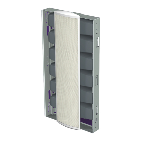
- Page 1 Owner’s Manual and Setup Procedures Vibration-Free Architectural Subwoofer System T h e P o w e r C l a r i t y...
-
Page 2: Table Of Contents
Important Safety Instructions BG Radia. We have assembled your system with the great- ..... . -
Page 3: Important Safety Instructions
Safety Instructions Important Safety Instructions 1. Read these instructions. 15. WARNING: Please refer the information on exterior rear en- closure for electrical and safety information before installing or 2. Keep these instructions. operating the apparatus. 3. Heed all warnings. 16. WARNING: To reduce the risk of fire or electric shock, do not 4. - Page 4 The BGX-A2 amplifier module contains DSP based equalization, home automation capabilities, and 2x1100W digital amplifiers to run the complete system. Each ampli- fier channel drives two BGX-S6B subwoofer modules in a parallel configuration or one BGX-S12B module. THX Technology THX Balanced Bass-Line™ Technology eliminates sound coloration due to wall vibration.
-
Page 5: Subwoofer Placement
BGX subwoofer installation height is not critical response of a subwoofer. These are position-dependent but the maximum output of the system can be increased... - Page 6 Subwoofer Placement (continued) Fig. 1 Recommended placement of subwoofer modules in-room Four subwoofer locations Typically yields smoother response Typically yields higher output Two subwoofer locations Typically yields higher output Typically yields smoother response 3535 Arrowhead Drive · Carson City, NV 89706 775-884-1900 ph ·...
-
Page 7: Construction Principles And Preparation
Construction Principles & Preparation Installation Considerations Construction Preparation The BGX subwoofer system has been designed primarily Generally BGX subwoofer modules do not require any with in-wall mounting in mind. However, since the woofers special preparation of wall or ceiling cavities for their are self contained (they do not rely on the wall cavity or a installation. -
Page 8: Retrofit Installation
Retrofit Installation Retrofit installation with 15” wide grille 4. Take the subwoofer module and install it inside the NCB 1. Remove the new construction bracket (NCB) from the using the four supplied machine screws. See detail in packaging and use it as a template for the drywall Fig. -
Page 9: New Construction Installation
New Construction Installation New construction installation 1. During pre-wire, pull wire to the planned subwoofer Fig. 4 on the left. Level the NCB if necessary using the locations. You will need (one) two-conductor wire per bend out metal tabs to account for any tolerance. woofer module (or one four-conductor wire per pair 3. -
Page 10: New Construction Installation
New Construction Installation (cont.) 4. When installing drywall, cut the opening around the 6. Take the 7” wide grille bezel without the grille material protective cover plate as shown on Fig. 5 on the left. installed and attach it to subwoofer module as shown in Fig. -
Page 11: Grille Options
Grille Options Grille Assembly Your choice of two grille sizes are available with the BGX subwoofer modules. One is 7” wide and is used primarily for new construction or when a thinner profile is desired and some drywall work is being done during installation. The other option is 15”... -
Page 12: Bgx-A2 Amplifier
When two amplifiers are used with four BGX-S12B sub precisely to the parameters of the subwoofer modules, the modules, the system achieves THX Ultra2 performance BGX-A2 is the heart of the finest subwoofer systems in the levels, and is the only in-wall subwoofer in the world which world. -
Page 13: System Hookup
BGX-A2 amplifiers to the system. into a live electrical socket until all connections are Note: Although the BGX-A2 is a two channel amplifier made and the entire system is ready to play. and the unbalanced and line out each have two jacks,... -
Page 14: System Configuration Settings
- Before connecting power, make sure the subwoofer’s frequency response. This is that both voltage selector switches show the proper particularly useful if your BGX subwoofer is being voltage (115V or 230V) for your location. sent a full-range signal (as would be the case using... -
Page 15: Amplifier Operation
Amplifier Operation BGX-A2 Music / Movie IR Sensor Gain Control Power Switch Mode Switch Receives infrared remote control Selects one of two This turns things on or Adjusts input signals from the included remote programmed equalization returns to standby. sensitivty of amp. -
Page 16: Remote Control
The IR Direct rear panel connection performs exactly Fig.12 Remote control functions the same functions as described above in the IR Remote BGX-A2 amplifier remote control with function buttons. Control section except it utilizes the rear panel electrical connection. Power Trigger Control A logic high (within the specified range) will turn on the system if it was previously off. -
Page 17: Amplifier Protection
Amplifier Protection System Protection The system incorporates several protection schemes to prevent component/system failure including: Short Circuit, Thermal Overload and Limiters. Short Circuit Protection Each speaker output connector can withstand a continuous shorted condition without permanent failure. However it is not advised to short the system for any reason. - Page 18 Serial Control RS-232 Communication (Home Automation Control) The following sequence describes the communication structure: The RS-232 port, located on the back of the unit, allows for a home automation system to remotely activate some <SOP><SOP><COMMAND><DATA><CHKSUM><EOP> of the basic functions and read back the settings. The automation scheme operates with host communication via = Start of packet indicator (0x0F and also a a PC, Crestron or any other device that can be programmed...
- Page 19 Serial Control RS-232 Commands in Detail Power Change (A0) The communication protocol includes three control characters so that any value transmitted can be interpreted The power change command includes turning ON and OFF as either data for processing or a functional indicator. The the system.
- Page 20 Serial Control Mode Change (A1) Level Change (A2) The mode change command includes switching between The level change command includes increasing and de- the Movie and Music modes. creasing the current level by 1dB. Movie Mode Level Up TX = 0F 0F A1 01 5E 04 TX = 0F 0F A2 01 5D 04 RX = 0F 0F A1 01 5E 04 (same as TX) RX = 0F 0F A2 01 5D 04 (same as TX)
- Page 21 Serial Control Level Specific Change (A3) The level specific change command allows instant selection of any level in the range -60dB to +7dB. TX = 0F 0F A3 (00 to 46) CHKSUM 04 RX = 0F 0F A3 (00 to 46) CHKSUM 04 (same as TX) The level function indicator and the new level setting will be shown even if the display was in its off state.
- Page 22 Notes...
- Page 23 All BG loudspeaker systems are warranted to the original purchaser for life against defects in materials and manufacture when used in properly designed systems. The warranty is five years for the BGX-A2 amplifier. Please record your loudspeaker’s information below for future reference.
- Page 24 T he Power of Clarity 3535 Arrowhead Drive · Carson City, NV 89706 775-884-1900 ph · 775-884-1276 fx · www.bgradia.com · sales@bgradia.com...
Need help?
Do you have a question about the BGX and is the answer not in the manual?
Questions and answers