
Related Manuals for NEC NP01WK


Summary of Contents for NEC NP01WK
- Page 1 Wall Mount Unit NP01WK/NP01WK1 Installation and Adjustment Manual English Deutsch Français Italano Español Português Русский Türkçe Polski 中文 한글 日本語 © NEC Display Solutions, Ltd. 2010 Printed in Croatia...
-
Page 2: Table Of Contents
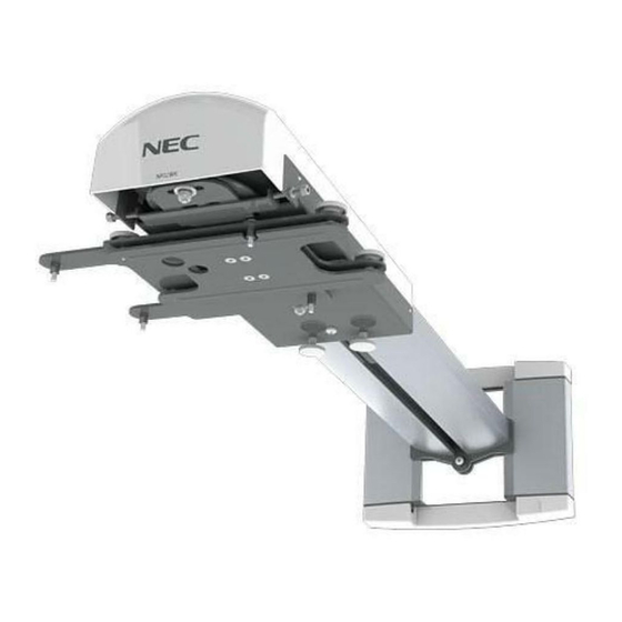
Wall Mount Unit NP01WK/NP01WK1 Installation and Adjustment Manual Thank you for your purchase of this NEC wall mount unit. Please read this installation and adjustment manual carefully to ensure proper use. The Wall Mount Unit NP01WK/NP01WK1 is exclusively for Projector U300X/U250X/ U310W/U260W and cannot be used for other projectors. -
Page 3: Please Heed The Following
Please heed the following Symbol In this “Installation and Adjustment Manual”, to ensure the safe and proper use of the product, prevent harm to yourself and others and damage to property, various symbols are used. The symbols and meanings are as follows. Please read this manual after ensuring the contents are well understood. - Page 4 Warning • Do not install in places subject to constant vibration. Extended vibration may cause loosening of the screws and result in the Wall Mount Unit and projector falling and causing injury. Also, it may cause breakdown of the projector. • To ensure safety, be sure to tighten the bolts, screws and adjusting knobs securely.
-
Page 5: Preparation
Preparation Packaged Parts Please check the packaged items. Cover (A, B):2 pairs Wall adapter:1 Plate (A) Arm cover:1 Arm:1 Plate (B):1 M4 screws:4 M3.5 screws:2 Hex wrench:1 Projector adapter:1 Installation and Adjustment Manual:1 Wall plate:1 *1 M5 screws:4 *2 *1, *2:To be used when mounting the wall adapter in the North America region. -
Page 6: Names Of Parts
Names of Parts Arm cover Elongate hole for screw (or bolt) (4 parts) Covers (A, B) • • Plate (A) • Arm fixation screw Grooves for wiring • • Tilt adjust knobs (4 parts) • • • • • Central axis •... -
Page 7: Dimensions Of Parts
Dimensions of Parts: (unit: mm) The dimensions of the positions of the wall fixation screws (bolts) of the wall adapter are described. Central axis The center of the wall adapter (central axis) 533 (minimum) -733 (maximum) Projector posterior surface Projector bottom surface (including the feet) ENG-6... -
Page 8: Mounting The Projector
Mounting the Projector Preparations 1. Determine the installation location of the screen, and accordingly decide the installation position of the wall mount unit. Refer to the section "Installation" in the user’s manual included with the projector for more information. • Installation for slanted projection is not possible. Determine the position for front projection. 2. - Page 9 c Align the projector adapter with the holes on the bottom of the projector and securely attach the adapter with the four supplied screws (M4x20). d Loosen the vertical adjust/arm fixation knobs of the projector adapter. Do not try to attach the projector adapter without the foam packing spacers in Caution place.
- Page 10 3. Attach the arm to the wall adapter. a Loosen the arm fixation screws (top and bottom) with the supplied hex wrench. b Insert the arm plate (A) into the wall adapter from the top and tighten the screws (top and bottom) near the center of the elongated hole.
- Page 11 b Use the two supplied M5.5x9.5 screws to securely attach the supplied plate (B) to the arm. c Remove the cable cover of the projector. Plate (B) Warning If plate (B) is not installed, the projector may slide out of the arm and fall off, which may cause injury.
- Page 12 5. Cabling a The power cord and signal cables can be passed through the grooves for wiring on the left and right side of the arm. This should be done before attaching the arm cover. Take care not to squeeze the cables with the horizontal adjust screws. This concludes the projector installation.
-
Page 13: Adjusting The Projection Position
Adjusting the Projection Position Preparations Before adjusting • Project an image from the projector, then first use the focus lever of the projector to roughly adjust the focus of the projected image. For information on how to project an image, see “Installation” in the user’s manual included with the projector. - Page 14 c Turn the left or right knob to adjust projector tilt in the left or right direction. - When the knob shown in black in the illustration i s t i g h t e n e d , t h e p ro j e c t o r i s ro t a t e d i n t h e counterclockwise direction.
- Page 15 4. Adjust the tilt. Tilt adjustment is performed with the four adjustment knobs. Front/rear tilt adjustment Adjust together Rotation axis Left/right tilt adjustment Fine adjustment in same direction as for vertical adjustment Adjust together Rotation axis • If tilt adjustment achieved with these knobs is not sufficient, repeat the adjustment process from step 2 on page ENG-12. • During adjustment, the position of the projected image may shift. In such a case, loosen the wall adapter and arm fixation screws and adjust the position.
- Page 16 5. Attach the covers to the projector adapter and the wall adapter. a Attach cover (A) (with hook) and cover (B) (with notch) to the upper side of the wall adapter. Slide the two covers towards the center while pushing them down, as shown in the illustration.
-
Page 17: Specifications
Specifications Product name: Wall mount unit Model: NP01WK/NP01WK1 Adjustment angle: Up-down angle ±3°, left-right angle ±3°, inclination angle ±10° Adjustment width: Front-rear ±100 mm, left-right ±50 mm, up-down ±50 mm External dimensions: 280 (W) x 541(D) x 219 (H) mm Weight: Approx. 6.2kg •Specifications and design are subject to change without notice. Using the wall plate (NP01WK1 only) The NP01WK1 is distributed in North America only.
Need help?
Do you have a question about the NP01WK and is the answer not in the manual?
Questions and answers