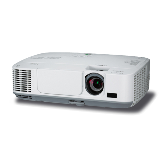
NEC NP-M260W Installation And Assembly Manual
Lightweight adjustable suspended ceiling plate for projector mounts
Hide thumbs
Also See for NP-M260W:
- User manual (155 pages) ,
- Installation and assembly manual (9 pages) ,
- Quick setup manual (7 pages)
Advertisement
Installation and Assembly:
Lightweight Adjustable Suspended Ceiling Plate for Projector
Mounts
Model: SCP200
U L
C
US
©
Maximum Load UL Capacity:
60 lb (27.2 kg)
ISSUED: 12-16-04 SHEET #: 120-9015-3 11-05-10
3215 W. North Ave. • Melrose Park, IL 60160 • (800) 865-2112 or (708) 865-8870 • Fax: (708) 865-2941 • www.peerlessmounts.com
Advertisement
Table of Contents

Summary of Contents for NEC NP-M260W
-
Page 1: Installation And Assembly
Installation and Assembly: Lightweight Adjustable Suspended Ceiling Plate for Projector Mounts Model: SCP200 © Maximum Load UL Capacity: 60 lb (27.2 kg) ISSUED: 12-16-04 SHEET #: 120-9015-3 11-05-10 3215 W. North Ave. • Melrose Park, IL 60160 • (800) 865-2112 or (708) 865-8870 • Fax: (708) 865-2941 • www.peerlessmounts.com... - Page 2 NOTE: Read entire instruction sheet before you start installation and assembly. WARNING • Do not begin to install your product until you have read and understood the instructions and warnings contained in this Installation Sheet. If you have any questions regarding any of the instructions or warnings, call Peerless customer care at 1-800-729-0307.
-
Page 3: Parts List
Before you start check the parts list to insure all of the parts shown are included. NOTE: You may not need all hardware provided. Parts List Description Qty. Part # A ceiling plate 055-2983 B M5 x 10 mm penta pin screw 505-9010 C M5 penta pin driver 520-9249... - Page 4 IMPORTANT: Ceiling Tray (A) is designed to fi t above a 24" (610 mm) x 24" (610 mm) section of a conventional suspended ceiling system. It may also be mounted above 24" x 48" conventional suspended ceiling. Ceiling runners (see fi gure 1.1) should have a "T" cross section and a minimum height of 1.5" (38 mm). Place ceiling tray (A) in grid above 24"...
- Page 5 Drill holes for four ceiling anchors (detail 2). Position the holes so that when the steel cables (E) are attached and taut they will angle out at 15°. DETAIL 2 Wood Joists or Beams Solid Concrete Drill 5/32" (4 mm) dia. Drill 5/16"...
- Page 6 LIMITED FIVE-YEAR WARRANTY Peerless Industries, Inc. establishes a warranty period of fi ve years for products manufactured or supplied by Peerless. This period commences from the date of sale of the product to the original consumer, but will in no case last for more than six years after the date of the product’s manufacture. During the warranty period such products will be free from defects in material and workmanship, provided they are installed and used in compliance with the instructions established by Peerless Industries, Inc.


Need help?
Do you have a question about the NP-M260W and is the answer not in the manual?
Questions and answers