Advertisement
Table of Contents
- 1 Parts List
- 2 Installation to Wood Joist Finished Ceilings, Exposed Wood Joists, or Wood Beam Ceilings
- 3 Installation to Concrete Ceilings
- 4 Flush Mount Application
- 5 Installation to Extension Column
- 6 Find Your Projector from the Models Listed below
- 7 Attach Projector, with Adapter Plate Already on It, to the Ball and Socket Mount
- Download this manual
Read instruction sheet before you start installation and assembly.
• Make sure that the supporting surface will safely support the combined load of the equipment and all attached hardware and
components.
IMPORTANT! Be sure not to touch the projector while tightening the set screw on the
ball and socket mount. This may cause the image to be unaligned when you let go.
IMPORTANT! Turn to the appropriate page for your ceiling installation.
Applications:
Flush Mount .................................................................................................................................................. page 5
Extension Column ........................................................................................................................................ page 6
Installations:
To Wood Joist Finished Ceilings,
Exposed Wood Joists, or Wood Beam Ceilings ........................................................................................ page 3
To Concrete Ceilings .................................................................................................................................... page 4
Visit the Peerless Web Site at www.peerlessmounts.com
Installation and Assembly -Ceiling Mount for
NEC NP 40/41/50/60/61/62/100/200 Projectors
WARNING
1 of 8
R
Maximum Load Capacity: 50 lb (22.7 kg)
ISSUED: 11-01-06 SHEET #: 055-9478-6
For customer care call 1-800-729-0307 or 708-865-8870.
Model: NP40CM
This product is intended for use with UL
Listed products and must be installed by a
qualified professional installer.
01-14-09
Advertisement
Table of Contents

Subscribe to Our Youtube Channel
Summary of Contents for NEC NP40CM
- Page 1 Exposed Wood Joists, or Wood Beam Ceilings ... page 3 To Concrete Ceilings ... page 4 Visit the Peerless Web Site at www.peerlessmounts.com Installation and Assembly -Ceiling Mount for NEC NP 40/41/50/60/61/62/100/200 Projectors Maximum Load Capacity: 50 lb (22.7 kg) WARNING 1 of 8...
-
Page 2: Parts List
Before you start check the parts list to insure all of the parts shown are included. Parts List Description A ball and socket mount B 4 mm security allen wrench C M5 x .8 x 10 mm socket pin type F screw D #10-32 x 3/8"... - Page 3 Exposed Wood Joists, or Wood Beam Ceilings Drill two 5/32" (4 mm) dia. holes to a minimum depth of 2.5" (64 mm). Attach ceiling plate (G) with two #14 x 2.5" (6 mm x 65 mm) wood screws (F) as shown using 3/8" (10 mm) socket wrench.
-
Page 4: Installation To Concrete Ceilings
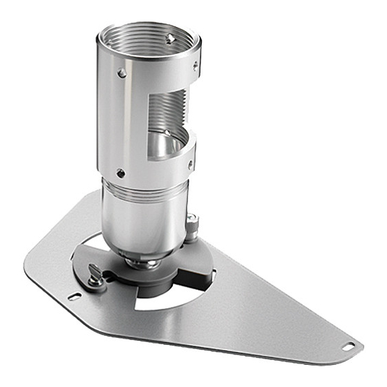
• When installing Peerless mounts on concrete, verify that you have a minimum of 1 5/8" of actual concrete surface in the 1/4" diameter hole to be used for the concrete anchors. Do not drill into mortar joints! Concrete must meet ASTM C-90 specifications. - Page 5 Flush Mount Application Screw ball and socket mount (A) into ceiling plate (G). Align the notch with one of the four holes of the ceiling plate (G) and secure ball and socket mount (A) with a M5 x 10 mm socket pin screw (C) using security allen wrench (B) as shown in detail 1.
- Page 6 Extension Column Screw extension column to ceiling plate (G). Align the notch with one of the four holes in the ceiling plate (G) and secure extension column with a M5 x 10 mm socket pin screw (C) using security allen wrench (B). See detail 4.
- Page 7 (R) into the threaded inserts as indicated below. Finish tightening M3 x 25 mm socket pin screws (N) using 2 mm security allen wrench (Q). Visit the Peerless Web Site at www.peerlessmounts.com A. NEC NP40/41/50/60/61/62 B. NEC NP100/200 7 of 8 ISSUED: 11-01-06 SHEET #: 055-9478-6 For customer care call 1-800-729-0307 or 708-865-8870.
- Page 8 Note: The projector adapter plate and projector you are installing may differ in appearance from the sample illustrated below. Attach projector, with adapter plate already on it, to the ball and socket mount (A) by inserting the ball and socket mount (A) into the adapter plate connection and twisting until the adapter plate will no longer turn (about 75°).


Need help?
Do you have a question about the NP40CM and is the answer not in the manual?
Questions and answers