Table of Contents
Advertisement
Advertisement
Table of Contents

Related Manuals for DFI NF4 SLI INFINITY


Summary of Contents for DFI NF4 SLI INFINITY
- Page 1 System Board User’s Manual 87100522...
- Page 2 Copyright This publication contains information that is protected by copyright. No part of it may be reproduced in any form or by any means or used to make any transformation/adaptation without the prior written permission from the copyright holders. This publication is provided for informational purposes only. The manufacturer makes no representations or warranties with respect to the contents or use of this manual and specifically disclaims any express or implied warranties of merchantability or fitness for any...
-
Page 3: Fcc And Doc Statement On Class B
FCC and DOC Statement on Class B This equipment has been tested and found to comply with the limits for a Class B digital device, pursuant to Part 15 of the FCC rules. These limits are designed to provide reasonable protection against harmful interference when the equipment is operated in a residential installation. -
Page 4: Table Of Contents
Introduction Table of Contents About this Manual................Warranty..................... Static Electricity Precaution..............Safety Measures..................About the Package................Before Using the System Board............Chapter 1 - Introduction..............Specifications........................... Special Features of the System Board..............Chapter 2 - Hardware Installation............ System Board Layout ......................System Memory.......................... -
Page 5: About This Manual
Introduction About this Manual This user’s manual contains detailed information about the system board. If, in some cases, some information doesn’t match those shown in the multilingual manual, the multilingual manual should al- ways be regarded as the most updated version. The multilingual manual is included in the system board package. -
Page 6: Static Electricity Precaution
Introduction Static Electricity Precautions It is quite easy to inadvertently damage your PC, system board, components or devices even before installing them in your system unit. Static electrical discharge can damage computer components without causing any signs of physical damage. You must take extra care in handling them to ensure against electrostatic build-up. -
Page 7: About The Package
Introduction About the Package The system board package contains the following items. If any of these items are missing or damaged, please contact your dealer or sales representative for assistance. The system board A user’s manual One IDE cable One floppy cable Two Serial ATA data cables One Serial ATA power cable One “nVRAID Driver”... -
Page 8: Chapter 1 - Introduction
Introduction Chapter 1 - Introduction Specifications Processor • AMD Athlon 64 FX / Athlon 64 / Sempron • Socket 939 Front Side Bus • 2000MT/s HyperTransport interface Chipset • NVIDIA nForce4 Supports NVIDIA SLI (Scalable Link Interface) System Memory • Four 184-pin DDR SDRAM DIMM sockets •... - Page 9 Introduction BIOS • Award BIOS • 4Mbit flash memory Energy Efficient Design • Suppor ts ACPI specification and OS Directed Power Management • Supports ACPI STR (Suspend to RAM) function • Wake-On-Events include: Wake-On-PS/2 Keyboard/Mouse Wake-On-USB Keyboard/Mouse Wake-On-LAN Wake-On-Ring RTC timer to power-on the system •...
- Page 10 Introduction Serial ATA Interface with NVIDIA RAID • Supports four Serial ATA ports • SATA speed up to 3Gb/s • NVIDIA RAID allows RAID arrays spanning across Serial ATA and Parallel ATA • RAID 0, RAID 1, RAID 0+1 and JBOD IEEE 1394 Interface •...
-
Page 11: Special Features Of The System Board
Introduction Special Features of the System Board AMD Athlon The system board supports the AMD Athlon 64 processor. AMD Athlon 64 provides superior computing for many software applications by allowing both 32-bit and 64-bit applications to run simultaneously on the same platform. The operating system and software are able to process more data and access a tremendous amount of memory which improves the overall system performance. - Page 12 Introduction PCI Express PCI Express is a high bandwidth I/O infrastructure that possesses the ability to scale speeds by forming multiple lanes. The system board currently supports the physical layer of x1 and x16 lane widths. The x1 PCI Express lane supports transfer rate of 2.5 Gigabytes (250MBbps) per second.
- Page 13 Introduction S/PDIF S/PDIF is a standard audio file transfer format that transfers digital audio signals to a device without having to be converted first to an analog format. This prevents the quality of the audio signal from degrading whenever it is converted to analog. S/PDIF is usually found on digital audio equipment such as a DAT machine or audio processing device.
- Page 14 Introduction USB Ports The system board supports USB 2.0 and USB 1.1 ports. USB 1.1 supports 12Mb/second bandwidth while USB 2.0 supports 480Mb/ second bandwidth providing a marked improvement in device transfer speeds between your computer and a wide range of simultaneously accessible external Plug and Play peripherals.
- Page 15 Introduction Wake-On-PS/2 Keyboard/Mouse This function allows you to use the PS/2 keyboard or PS/2 mouse to power-on the system. Important: The 5VSB power source of your power supply must support 720mA. Wake-On-USB Keyboard/Mouse This function allows you to use a USB keyboard or USB mouse to wake up a system from the S3 (STR - Suspend To RAM) state.
- Page 16 Introduction Important: The 5VSB power source of your power supply must support AC Power Failure Recovery When power returns after an AC power failure, you may choose to either power-on the system manually, let the system power-on automatically or return to the state where you left off before power failure occurs.
-
Page 17: Chapter 2 - Hardware Installation
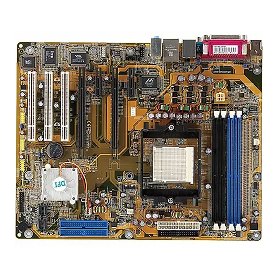
Hardware Installation Chapter 2 - Hardware Installation System Board Layout... -
Page 18: System Memory
Hardware Installation Warning: Electrostatic discharge (ESD) can damage your system board, processor, disk drives, add-in boards, and other components. Perform the upgrade instruction procedures described at an ESD workstation only. If such a station is not available, you can provide some ESD protection by wearing an antistatic wrist strap and attaching it to a metal part of the system chassis. -
Page 19: Hardware Installation
Hardware Installation The system board supports the following memory interface. Single Channel (SC) Data will be accessed in chunks of 64 bits (8B) from the memory channels. Dual Channel (DC) Data will be accessed in chunks of 128 bits from the memory channels. - Page 20 Hardware Installation Important Notes on Memory Usage 1. The system board will fail to boot when 3 DIMMs are used. The integrated memory controller in AMD's 64-bit Socket 939 series CPU supports dual channel however when 3 DIMMs are installed, the controller is not capable of accurately distinguishing between dual and single channels resulting to boot up problem.
-
Page 21: Installing The Dim Module
Hardware Installation Installing the DIM Module A DIM module simply snaps into a DIMM socket on the system board. Pin 1 of the DIM module must correspond with Pin 1 of the socket. Notch Pin 1 1. Pull the “tabs” which are at the ends of the socket to the side. 2. -
Page 22: Cpu
Hardware Installation Overview The system board is equipped with a surface mount 939-pin CPU socket. This socket is exclusively designed for installing an AMD CPU. Installing the CPU 1. Make sure the PC and all other peripheral devices connected to it has been powered down. - Page 23 Hardware Installation 4. Unlock the socket by pushing the lever sideways, away from the socket, then lifting it up to a 90 angle. Make sure the lever is lifted to at least this angle otherwise the CPU will not fit in properly. Lever 5.
- Page 24 Hardware Installation 6. Insert the CPU into the socket until it is seated in place. The CPU will fit in only one orientation and can easily be inserted without exerting any force. Important: Do not force the CPU into the socket. Forcing the CPU into the socket may bend the pins and damage the CPU.
-
Page 25: Installing The Fan And Heat Sink
Hardware Installation Installing the Fan and Heat Sink The CPU must be kept cool by using a CPU fan with heat sink. Without sufficient air circulation across the CPU and heat sink, the CPU will overheat damaging both the CPU and system board. Note: •... - Page 26 Hardware Installation 3. Place the heat sink on top of the CPU. Now hook one side of the retention clip onto the retention module base by fitting the holes on the retention clip into the retaining tabs of the retention module base.
- Page 27 Hardware Installation 4. Hook the other side of the retention clip (the one near the retention lever) so that the holes on the retention clip also fit into the retaining tabs of the retention module base. Note: You will not be able to secure the fan and heat sink assembly in place if it did not fit properly onto the retention module base.
-
Page 28: Jumper Settings
Hardware Installation Jumper Settings Clear CMOS Data 1-2 On: Normal 2-3 On: (default) Clear CMOS Data If you encounter the following, a) CMOS data becomes corrupted. b) You forgot the supervisor or user password. c) You are unable to boot-up the computer system because the processor’s ratio/clock was incorrectly set in the BIOS. - Page 29 Hardware Installation 4. After powering-on the system, press <Del> to enter the main menu of the BIOS. 5. Select the Genie BIOS Setting submenu and press <Enter>. 6. Set the processor’s clock/ratio to its default setting or an appro- priate bus clock or ratio. Refer to the Genie BIOS Setting section in chapter 3 for more information.
- Page 30 Hardware Installation PS/2 Power Select 1-2 On: 5V 2-3 On: 5VSB (default) JP7 is used to select the power of the PS/2 keyboard/mouse port. Selecting 5VSB will allow you to use the PS/2 keyboard or PS/2 mouse to wake up the system. BIOS Setting Configure the PS/2 keyboard/mouse wake up function in the Integrated Peripherals submenu (“Onboard Device”...
-
Page 31: Usb Power Select
Hardware Installation USB Power Select USB 1-4 (JP5) 1-2 On: 5V 2-3 On: 5VSB (default) USB 5-10 (JP6) 1-2 On: 5V 2-3 On: 5VSB (default) JP5 and JP6 are used to select the power of the USB ports. Selecting 5VSB will allow you to use the USB keyboard or USB mouse to wake up the system. -
Page 32: Rear Panel I/O Ports
Hardware Installation Rear Panel I/O Ports PS/2 Parallel Mouse 1394_1 Line-in Line-out Mic-in PS/2 S/PDIF-in USB 1-2 USB 3-4 S/PDIF-out The rear panel I/O ports consist of the following: • PS/2 mouse port • PS/2 keyboard port • Parallel port •... - Page 33 Hardware Installation PS/2 Mouse and PS/2 Keyboard Ports PS/2 Mouse PS/2 Keyboard The system board is equipped with an onboard PS/2 mouse (Green) and PS/2 keyboard (Purple) ports - both at location CN2 of the system board. The PS/2 mouse port uses IRQ12. If a mouse is not connected to this port, the system will reserve IRQ12 for other expansion cards.
-
Page 34: Parallel Port
Hardware Installation 2.5.2 Parallel Port Parallel The system board has a standard parallel port (Burgundy) at loca- tion CN8 for interfacing your PC to a parallel printer. It supports SPP, ECP and EPP. Setting Function Allows normal speed operation but (Standard Parallel Port) in one direction only. - Page 35 Hardware Installation S/PDIF-in/out Jacks S/PDIF-out S/PDIF-in SPDIF out SPDIF in The system board is equipped with an onboard S/PDIF-out RCA jack (yellow) and S/PDIF-in RCA jack (red) jacks at locations CN5 and CN7 respectively. The S/PDIF connector at location J3 is used to connect to optical S/PDIF ports.
-
Page 36: Serial Port
Hardware Installation 2.5.4 Serial Port The system board is equipped with an onboard serial port (Teal/ Turquoise) at location CN1. The serial por t is an RS-232C asynchronous communication por t with 16C550A-compatible UARTs that can be used with a modem, serial printer, remote dis- play terminal or other serial devices. - Page 37 Hardware Installation IEEE 1394 1394_1 1394_2 1 2 The system board is equipped with an onboard IEEE 1394 port at location CN3 (IEEE 1394_1) of the system board. It is also equipped with an IEEE 1394 connector at location J8 (1394_2) for connecting an additional 1394 device.
-
Page 38: Universal Serial Bus Ports
Hardware Installation Universal Serial Bus Ports USB 2 USB 1 USB 4 USB 3 USB 5-6 USB 9-10 USB 7-8 The system board supports 10 USB 2.0/1.1 ports. USB allows data exchange between your computer and a wide range of simultaneously accessible external Plug and Play peripherals. - Page 39 Hardware Installation Driver Installation You may need to install the proper drivers in your operating system to use the USB device. Refer to your operating system’s manual or documentation for more information. Refer to chapter 4 for more information about installing the USB 2.0 driver.
-
Page 40: Rj45 Lan Port
Hardware Installation RJ45 LAN Port The system board is equipped with an onboard RJ45 LAN port at location CN4. LAN allows the system board to connect to a local area network by means of a network hub. BIOS Setting Configure the onboard LAN in the Integrated Peripherals submenu of the BIOS. -
Page 41: Audio (Rear Audio And Front Audio)
Hardware Installation Audio (Rear Audio and Front Audio) Rear audio Line-in Line-out Mic-in Front audio Rear Audio • Line-in (Light Blue) In a 2-channel mode, this jack is used to connect any audio devices such as Hi-fi set, CD player, tape player, AM/FM radio tuner, synthesizer, etc. - Page 42 Hardware Installation 2-channel 6-channel 4-channel Light Blue Line-in Rear R/L Rear R/L Lime Line-out Front R/L Front R/L Pink Mic-in Center/Subwoofer Mic-in Front Audio The front audio connector (J4) allows you to connect to the line-out and mic-in jacks that are at the front panel of your system. Using this connector will disable the rear audio’s line-out and mic-in func- tions.
-
Page 43: I/O Connectors
Hardware Installation I/O Connectors CD-in Internal Audio Connector Left audio channel Ground Ground Right audio channel The CD-in (J1) connector is used to receive audio from a CD-ROM drive, TV tuner or MPEG card. -
Page 44: Floppy Disk Drive Connector
Hardware Installation Floppy Disk Drive Connector The system board is equipped with a floppy disk drive connector that supports two standard floppy disk drives. To prevent improper floppy cable installation, the floppy disk header has a keying mechanism. The 34-pin connector on the floppy cable can be placed into the header only if pin 1 of the connector is aligned with pin 1 of the header. -
Page 45: Serial Ata Connectors
Hardware Installation Serial ATA Connectors SATA 4 (J10) SATA 1 (J13) SATA 3 (J2) SATA 2 (J11) • SATA speed up to 3Gb/s • RAID 0, RAID 1, RAID 0+1 and JBOD • NVIDIA RAID allows RAID arrays spanning across Serial ATA and Parallel ATA Connecting Serial ATA Cables Connect one end of the Serial ATA cable to the Serial ATA... - Page 46 Hardware Installation 4. When the system powers-up, the NVRAID BIOS status message screen will appear. Press the <F10> key to enter the utility. The utility allows you to build a RAID system on Serial ATA drives and Parallel ATA drives. 5.
-
Page 47: Ide Disk Drive Connector
Hardware Installation IDE Disk Drive Connector IDE 2 IDE 1 Configuring RAID on IDE Drives The system board allows configuring RAID across Parallel ATA drives and Serial ATA drives. It supports RAID 0, RAID 1, RAID 0+1 and JBOD. For optimal performance, install identical drives of the same model and capacity. - Page 48 Hardware Installation 5. Install the NVRAID driver. ® If you are in the process of installing Windows XP or ® Windows 2000 on RAID configured Serial ATA drives, you will need the provided nVRAID driver floppy diskette. If you are ®...
- Page 49 Hardware Installation Adding a Second IDE Disk Drive When using two IDE drives, one must be set as the master and the other as the slave. Follow the instructions provided by the drive manufacturer for setting the jumpers and/or switches on the drives. The system board suppor ts Enhanced IDE or ATA-2, ATA/33, ATA/66 or ATA/100 hard drives.
-
Page 50: Irda Connector
Hardware Installation IrDA Connector IRRX Ground N. C. IRTX Connect the cable connector from the IrDA module to the IrDA connector (J5). Note: The sequence of the pin functions on some IrDA cable may be reversed from the pin function defined on the system board. Make sure to connect the cable connector to the IrDA connector according to their pin functions. -
Page 51: Cooling Fan Connectors
Hardware Installation Cooling Fan Connectors Sense Ground Power System fan CPU fan Sense Power Ground Chipset fan Ground Sense Power Connect the CPU fan’s cable connector to the CPU fan connector (J30) on the system board. The system fan (J31) and chipset fan (J32) are used to connect additional cooling fans. - Page 52 Hardware Installation LEDs DRAM Power LED Standby Power LED DRAM Power LED This LED will light when the system’s power is on. Standby Power LED This LED will light when the system is in the standby mode.
-
Page 53: Power Connectors
Hardware Installation Power Connectors +12V Ground 1 3 1 +3.3VDC +3.3VDC -12VDC +3.3VDC Ground +5VDC PS_ON# +12V +5VDC PWR_OK +5VSB +5VDC +12VDC +5VDC +5VDC +12VDC +3.3VDC Ground Ground +12V 5V/12V Use a power supply that complies with the ATX12V Power Supply Design Guide Version 1.1. - Page 54 Hardware Installation The system board requires a minimum of 300 Watt power supply to operate. Your system configuration (CPU power, amount of memory, add-in cards, peripherals, etc.) may exceed the minimum power requirement. To ensure that adequate power is provided, we strongly recommend that you use a minimum of 400 Watt (or greater) power supply.
-
Page 55: Front Panel Connectors
Hardware Installation Front Panel Connectors ATX-SW PWR-LED HD-LED SPEAKER RESET HD-LED: Primary/Secondary IDE LED This LED will light when the hard drive is being accessed. RESET: Reset Switch This switch allows you to reboot without having to power off the system thus prolonging the life of the power supply or system. - Page 56 Hardware Installation PWR-LED: Power/Standby LED When the system’s power is on, this LED will light. When the system is in the S1 (POS - Power On Suspend) or S3 (STR - Suspend To RAM) state, it will blink every second. Note: If a system did not boot-up and the Power/Standby LED did not light after it was powered-on, it may indicate that the CPU...
-
Page 57: Pci Express Slots
Hardware Installation PCI Express Slots PCI Express x1 PCI Express x16 PCI Express x1 PCI Express x16 PCI Express x16 Install PCI Express x16 graphics card, that comply to the PCI Express specifications, into the PCI Express x16 slot. For SLI mode, install 2 SLI-ready PCI Express x16 graphics cards (use identical cards) on the PCI Express x16 slots. -
Page 58: Sli Technology
Hardware Installation SLI Technology ® The NVIDIA (Scalable Link Interface) technology connects two identical SLI-ready PCI Express x16 graphics cards in a single and scalable system. Using the SLI bridge to connect two identical graphics cards will provide extreme performance allowing you to enjoy games with the most visual effects and the most graphics demanding multimedia utilities. - Page 59 Hardware Installation The PCI Express Slots The illustration below shows the bandwidth of the PCI Express slots. Bandwidth x1 PCI Express slot x16 PCI Express slot x1 PCI Express slot x16 PCI Express slot...
- Page 60 Hardware Installation Installing the Graphics Cards Important: Use two identical NVIDIA SLI-ready PCI Express x16 graphics cards. 1. To install the first graphics card, remove the screw of the bracket that is opposite the PCIE1 slot then remove the bracket. 2.
- Page 61 Hardware Installation 7. The distinctive feature of an SLI-ready graphics card is the presence of the SLI connector (goldfingers) on the card. 8. Align the SLI bridge (included in the system board package) above the SLI connector of the graphics cards then insert the bridge until it is properly seated in place.
- Page 62 Hardware Installation 9. Connect a 4-pin power cable from the power supply unit to the 5V/12V connector that is on the system board. Power cable 5V/12V connector...
-
Page 63: Chapter 3 - Bios Setup
BIOS Setup Chapter 3 - BIOS Setup Award BIOS Setup Utility The Basic Input/Output System (BIOS) is a program that takes care of the basic level of communication between the processor and peripherals. In addition, the BIOS also contains codes for various advanced features found in this system board. -
Page 64: Bios Setup
BIOS Setup Standard CMOS Features Use the arrow keys to highlight “Standard CMOS Features” and press <Enter>. A screen similar to the one below will appear. The settings on the screen are for reference only. Your version may not be identical to this one. - Page 65 BIOS Setup IDE Channel 0 Master, IDE Channel 0 Slave, IDE Channel 1 Master and IDE Channel 1 Slave Move the cursor to a field then press <Enter>. The following screen will appear. The settings on the screen are for reference only. Your version may not be identical to this one.
- Page 66 BIOS Setup Capacity Displays the approximate capacity of the disk drive. Usually the size is slightly greater than the size of a formatted disk given by a disk checking program. Cylinder This field displays the number of cylinders. Head This field displays the number of read/write heads. Precomp This field displays the number of cylinders at which to change the write timing.
- Page 67 BIOS Setup Video This field selects the type of video adapter used for the primary system monitor. Although secondary monitors are supported, you do not have to select the type. The default setting is EGA/VGA. EGA/VGA Enhanced Graphics Adapter/Video Graphics Array. For EGA, VGA, SVGA and PGA monitor adapters.
- Page 68 BIOS Setup Extended Memory Displays the amount of extended memory detected during boot-up. Total Memory Displays the total memory available in the system.
-
Page 69: Advanced Bios Features
BIOS Setup Advanced BIOS Features The Advanced BIOS Features allows you to configure your system for basic operation. Some entries are defaults required by the system board, while others, if enabled, will improve the performance of your system or let you set some features according to your preference. The screen above list all the fields available in the Advanced BIOS Features submenu, for ease of reference in this manual. - Page 70 BIOS Setup Removable Device Priority This field is used to select the boot sequence of the removable devices. Move the cursor to this field then press <Enter>. Use the Up or Down arrow keys to select a device then press <+> to move it up or <->...
- Page 71 BIOS Setup Hard Disk Boot Priority This field is used to select the boot sequence of the hard drives. Move the cursor to this field then press <Enter>. Use the Up or Down arrow keys to select a device then press <+> to move it up or <->...
- Page 72 BIOS Setup Quick Power On Self Test This field speeds up Power On Self Test (POST) whenever the system is powered on. The BIOS will shorten or skip some check items during POST. To attain the shor test POST time, select “Enabled”.
- Page 73 BIOS Setup Gate A20 Option This field allows you to select how gate A20 is handled. Gate A20 is a device used to address memory above 1 Mbyte. Initially, gate A20 was handled via the keyboard controller. Today, while keyboards still provide this support, it is more common, and much faster, for the system chipset to provide support for gate A20.
- Page 74 BIOS Setup Security Option This field determines when the system will prompt for the password - everytime the system boots or only when you enter the BIOS setup. Set the password in the Set Supervisor/User Password submenu. System The system will not boot and access to Setup will be denied unless the correct password is entered at the prompt.
- Page 75 BIOS Setup Full Screen Logo Show This field is applicable only if you want a particular logo to appear during system boot-up. Enabled The logo will appear in full screen during system boot- Disabled The logo will not appear during system boot-up. Small Logo(EPA) Show Enabled The EPA logo will appear during system boot-up.
-
Page 76: Advanced Chipset Features
BIOS Setup Advanced Chipset Features The settings on the screen are for reference only. Your version may not be identical to this one. This section gives you functions to configure the system based on the specific features of the chipset. The chipset manages bus speeds and access to system memory resources. - Page 77 BIOS Setup SSE/SSE2 Instructions The options are Enabled and Disabled. MAC PHY IEEE Test The options are Enabled and Disabled. System BIOS Cacheable When this field is enabled, accesses to the system BIOS ROM addressed at F0000H-FFFFFH are cached, provided that the cache controller is enabled.
-
Page 78: Integrated Peripherals
BIOS Setup Integrated Peripherals The settings on the screen are for reference only. Your version may not be identical to this one. IDE Function Setup The settings on the screen are for reference only. Your version may not be identical to this one. - Page 79 BIOS Setup Primary Master/Slave PIO and Secondary Master/Slave PIO PIO means Programmed Input/Output. Rather than have the BIOS issue a series of commands to effect a transfer to or from the disk drive, PIO allows the BIOS to tell the controller what it wants and then let the controller and the CPU perform the complete task by themselves.
- Page 80 BIOS Setup IDE Prefetch Mode This allows data and addresses to be stored in the internal buffer of the chip, thus reducing access time. Enable this field to achieve better performance. IDE HDD Block Mode Enabled The IDE HDD uses the block mode. The system BIOS will check the hard disk drive for the maximum block size the system can transfer.
- Page 81 BIOS Setup SATA-2 Primary Master RAID and SATA-2 Secondary Master RAID These fields are used to enable or disable the RAID function of Serial ATA’s second channel (SATA 3 and SATA 4). Onboard Device Move the cursor to this field and press <Enter>. The following screen will appear.
- Page 82 BIOS Setup Mouse Right When this option is selected, double-click the right button of the mouse to power-on the system. Any Key Press any key to power-on the system. Keyboard 98 When this option is selected, press the “wake up” key of the Windows 98 compatible keyboard to power-on the system.
- Page 83 BIOS Setup UART Mode Select This field is used to select the type of IrDA standard supported by your IrDA device. For better transmission of data, your IrDA peripheral device must be within a 30 angle and within a distance of 1 meter.
- Page 84 BIOS Setup USB Keyboard Support If you are using a USB keyboard device, set this field to Enabled. USB Mouse Support If you are using a USB mouse, set this field to Enabled. USB Park Mode The options are Enabled and Disabled. USB TD Reads The options are non-ISO Queue and ISO Queue.
-
Page 85: Power Management Setup
BIOS Setup Power Management Setup The Power Management Setup allows you to configure your system to most effectively save energy. The settings on the screen are for reference only. Your version may not be identical to this one. ACPI Function This function should be enabled only in operating systems that ®... - Page 86 BIOS Setup Power Management This field allows you to select the type (or degree) of power saving by changing the length of idle time that elapses before the “HDD Power Down” field is activated. Min Saving Minimum power saving time for the “HDD Power Down”...
- Page 87 BIOS Setup Soft-Off by PBTN This field allows you to select the method of powering off your system. Delay 4 Sec. Regardless of whether the Power Management func- tion is enabled or disabled, if the power button is pushed and released in less than 4 sec, the system enters the Suspend mode.
- Page 88 BIOS Setup Power-On By Alarm Enabled When Enabled, you can set the time you would like the Soft Power Down (Soft-Off) PC to power-on in the “Time (dd:hh:mm) of Alarm” field. However, if the system is being accessed by incoming calls or the net- work prior to the time set in the field, the system will give priority to the incoming calls or network.
- Page 89 BIOS Setup PnP/PCI Configurations This section describes configuring the PCI bus system. It covers some very technical items and it is strongly recommended that only experienced users should make any changes to the default settings. The settings on the screen are for reference only. Your version may not be identical to this one.
- Page 90 BIOS Setup IRQ Resources Move the cursor to this field and press <Enter>. This field is used to set each system interrupt to either Reserved or PCI Device. The settings on the screen are for reference only. Your version may not be identical to this one.
-
Page 91: Pc Health Status
BIOS Setup PC Health Status The settings on the screen are for reference only. Your version may not be identical to this one. Shutdown Temperature You can prevent the system from overheating by selecting a temperature in this field. If the system detected that its temperature exceeded the one set in this field, it will automatically shutdown. -
Page 92: Genie Bios Setting
BIOS Setup Genie BIOS Setting The settings on the screen are for reference only. Your version may not be identical to this one. Current CPU Frequency is This field will show the detected frequency of the CPU. Hammer Fid Control This field is used to select the CPU FSB’s operating frequency. - Page 93 BIOS Setup DRAM Configuration Move the cursor to this field and press <Enter>. The following screen will appear. The screen above list all the fields available in the DRAM Configuration submenu, for ease of reference in this manual. In the actual CMOS setup, you have to use the scroll bar to view the fields.
- Page 94 BIOS Setup CAS# Latency (Tcl) This field is used to select the clock cycle of the CAS latency time. The option selected specifies the timing delay before SDRAM starts a read command after receiving it. Min RAS# Active Time (Tras) This field is used to select the minimum time RAS takes to read from and write to a memory cell.
- Page 95 BIOS Setup Write Recovery Time (Twr) This field is used to select the write recovery time when the DRAM safely registers the last write data. This is the time from the last write data to precharge. Write to Read Delay (Twtr) This field is used to select the write to read delay time.
- Page 96 BIOS Setup Bottom of 32-bit [31:24] IO This field is used to select the memory that will be remapped to an address higher than 00E0. 1T/2T Memory Timing 2T timing which provides better system stability is supported in CG or later revisions of the AMD Athlon 64 CPU.
- Page 97 BIOS Setup Enable All DIMM Clock This field is used to enable or disable all DIMM clock. S/W Memory Hole Remapping This field is used to enable the software to remap the physical memory to an address higher than 00E0. MTRR Mapping Mode This field is used to disable or continue the MTRR mapping mode.
- Page 98 BIOS Setup AMD K8 Cool & Quiet Auto Enables AMD’s Cool‘n’Quiet technology. This function allows the system to detect the CPU’s tasks and utilization status. When the CPU’s task slows down, the system effectively lowers power consumption by changing its CPU speed and voltage, subsequently decreasing its noise level.
- Page 99 BIOS Setup CPU Voltage Offset This field allows you to manually adjust to a higher core voltage that is supplied to the CPU. If you want to use the CPU’s default core voltage, leave this field in its default setting. The CPU’s Vcore will be generated according to the CPU VID configuration.
- Page 100 BIOS Setup Load Fail-Safe Defaults The “Load Fail-Safe Defaults” option loads the troubleshooting default values permanently stored in the ROM chips. These settings are not optimal and turn off all high performance features. You should use these values only if you have hardware problems. Highlight this option in the main menu and press <Enter>.
-
Page 101: Load Optimized Defaults
BIOS Setup Load Optimized Defaults The “Load Optimized Defaults” option loads optimized settings from the BIOS ROM. Use the default values as standard values for your system. Highlight this option in the main menu and press <Enter>. Type <Y> and press <Enter> to load the Setup default values. -
Page 102: Set Supervisor Password
BIOS Setup Set Supervisor Password If you want to protect your system and setup from unauthorized entry, set a supervisor’s password with the “System” option selected in the Advanced BIOS Features. If you want to protect access to setup only, but not your system, set a supervisor’s password with the “Setup”... - Page 103 BIOS Setup Set User Password If you want another user to have access only to your system but not to setup, set a user’s password with the “System” option se- lected in the Advanced BIOS Features. If you want a user to enter a password when trying to access setup, set a user’s password with the “Setup”...
- Page 104 BIOS Setup Save & Exit Setup When all the changes have been made, highlight “Save & Exit Setup” and press <Enter>. Type “Y” and press <Enter>. The modifications you have made will be written into the CMOS memory, and the system will reboot. You will once again see the initial diagnostics on the screen.
-
Page 105: Exit Without Saving
BIOS Setup Exit Without Saving When you do not want to save the changes you have made, highlight “Exit Without Saving” and press <Enter>. Type “Y” and press <Enter>. The system will reboot and you will once again see the initial diagnostics on the screen. If you wish to make any changes to the setup, press <Ctrl>... -
Page 106: Nvraid Bios
BIOS Setup NVRAID BIOS The NVRAID BIOS utility is used to configure and manage RAID on Serial ATA drives (SATA 1 to SATA 4) and Parallel ATA drives. After you power up the system and all drives have been detected, the NVRAID BIOS status message screen will appear. -
Page 107: Updating The Bios
Updating the BIOS To update the BIOS, you will need the new BIOS file and a flash utility, AWDFLASH.EXE. You can download them from DFI’s web site or contact technical support or your sales representative. 1. Save the new BIOS file along with the flash utility AWDFLASH.EXE to a floppy disk. - Page 108 BIOS Setup 6. The following will appear. Do You Want to Save BIOS (Y/N) This question refers to the current existing BIOS in your system. We recommend that you save the current BIOS and its flash utility; just in case you need to reinstall the BIOS. To save the current BIOS, press <Y>...
-
Page 109: Chapter 4 - Supported Softwares
Supported Software Chapter 4 - Supported Software Drivers, Utilities and Software Applications The CD that came with the system board contains drivers, utilities and software applications required to enhance the performance of the system board. Inser t the CD into a CD-ROM drive. The autorun screen (Mainboard Utility CD) will appear. -
Page 110: Supported Software
Supported Software Microsoft DirectX 9 To install, please follow the steps below. 1. On the left side of the autorun screen, click the “TOOLS” icon. 2. Click “Microsoft DirectX 9” on the main menu. The following screen will appear. 3. Click “I accept the agreement” then click “Next”. 4. - Page 111 Supported Software NVIDIA Windows nForce Drivers The NVIDIA Windows nForce Drivers contains the following. • NVIDIA SMBus Driver • NVIDIA Ethernet Driver • NVIDIA IDE Driver To install NVIDIA Windows nForce Drivers, please follow the steps below. 1. On the left side of the autorun screen, click the “CHIPSET” icon. 2.
- Page 112 Supported Software 3. The following screen will appear. Select the drivers you want to install. The drivers will be installed automatically. Make sure you have selected “NVIDIA IDE Driver” because this driver will replace Windows ATA drivers enabling the processor and other system level hardware to be more productive and efficient.
- Page 113 Supported Software NVIDIA Firewall and ForceWare Network Access Manager To install, please follow the steps below. 1. On the left side of the autorun screen, click the “TOOLS” icon. 2. Click “NVIDIA Firewall and ForceWare Network Access Manager” on the main menu. The following screen will appear.
- Page 114 Supported Software 3. Select the type of setup you prefer then click “Next”. 4. Click “Yes” to activate Firewall.
- Page 115 Supported Software 5. Click “Finish” to exit setup. NVIDIA ForceWare Network Access Manager After completing installation, the “NVIDIA web-based...” icon is automatically created on your desktop. Double-click this icon to launch the NVIDIA ForceWare Network Access Manager utility. The utility allows you to configure the Ethernet interface features and personal Firewall for optimized security.
- Page 116 Supported Software RAID Driver for NVIDIA nForce4 The steps below describe configuring RAID on Serial ATA and Parallel ATA drives. 1. Run the Award BIOS setup utility then go to the Integrated Pe- ripherals submenu - “RAID Config” section of the BIOS. 2.
- Page 117 Supported Software Now the following steps are extremely crucial because there are 2 essential files that must be installed here. Press <S> to select “Specify Additional Device”. At this point you will be prompted to insert a floppy disk containing the RAID driver. Inser t the “NVRAID Driver” diskette.
- Page 118 Supported Software nTune NVIDIA nTune is an easy monitoring application that allows tuning of gaming performance, setting the system to quiet operation when playing DVD and monitoring the system functions. nTune is the safest way to change the bus speeds, memory timings, adjust voltages and update the BIOS.
- Page 119 Supported Software Click “NView” to configure desktop management. Click “Update My BIOS” to update the current BIOS.
-
Page 120: Realtek Audio Driver
Supported Software Realtek Audio Driver To install, please follow the steps below. 1. On the left side of the autorun screen, click the “AUDIO” icon. 2. Click “Audio Driver” on the main menu. The following screen will appear. 3. Follow the prompts on the screen to complete installation. 4. -
Page 121: Installation Notes
2. All steps or procedures to install software drivers are subject to change without notice as the softwares are occassionally updated. Please go to DFI's web site at "http://www.dfi.com/support1/ download2.asp" for the latest version of the drivers or software applications. -
Page 122: Appendix A - System Error Messages
System Error Message Appendix A - System Error Message When the BIOS encounters an error that requires the user to correct something, either a beep code will sound or a message will be displayed in a box in the middle of the screen and the message, PRESS F1 TO CONTINUE, CTRL-ALT-ESC or DEL TO ENTER SETUP, will be shown in the information box at the bottom. - Page 123 System Error Message setting than indicated in Setup. Determine which setting is correct, either turn off the system and change the jumper or enter Setup and change the VIDEO selection. FLOPPY DISK(S) fail (80) Unable to reset floppy subsystem. FLOPPY DISK(S) fail (40) Floppy type mismatch.
-
Page 124: Appendix B - Troubleshooting
Troubleshooting Appendix B - Troubleshooting B.1 Troubleshooting Checklist This chapter of the manual is designed to help you with problems that you may encounter with your personal computer. To efficiently troubleshoot your system, treat each problem individually. This is to ensure an accurate diagnosis of the problem in case a problem has multiple causes. -
Page 125: Power Supply
Troubleshooting The picture seems to be constantly moving. 1. The monitor has lost its vertical sync. Adjust the monitor’s vertical sync. 2. Move away any objects, such as another monitor or fan, that may be creating a magnetic field around the display. 3. -
Page 126: Hard Drive
Troubleshooting Hard Drive Hard disk failure. 1. Make sure the correct drive type for the hard disk drive has been entered in the BIOS. 2. If the system is configured with two hard drives, make sure the bootable (first) hard drive is configured as Master and the sec- ond hard drive is configured as Slave. -
Page 127: System Board
Troubleshooting 3. Verify that the attached serial device works by attaching it to a serial port that is working and configured correctly. If the serial device does not work, either the cable or the serial device has a problem. If the serial device works, the problem may be due to the onboard I/O or the address setting.
Need help?
Do you have a question about the NF4 SLI INFINITY and is the answer not in the manual?
Questions and answers