Table of Contents
Advertisement
Quick Links
Advertisement
Table of Contents

Subscribe to Our Youtube Channel
Related Manuals for DFI nF4X Infinity


Summary of Contents for DFI nF4X Infinity
- Page 1 System Board User’s Manual Carte Mère Manuel Pour Utilisateur System-Platine Benutzerhandbuch Manual del Usuario de Placas Base Ðóêîâîäñòâî Ïîëüçîâàòåëÿ Ðóêîâîäñòâî Ïîëüçîâàòåëÿ Ðóêîâîäñòâî Ïîëüçîâàòåëÿ Ðóêîâîäñòâî Ïîëüçîâàòåëÿ Ðóêîâîäñòâî Ïîëüçîâàòåëÿ 935-CK8045-500 86510523...
- Page 2 Quick Setup Guide Copyright This publication contains information that is protected by copyright. No part of it may be reproduced in any form or by any means or used to make any transformation/adaptation without the prior written permission from the copyright holders.
- Page 3 Table of Contents Chapter 1 Quick Setup Guide... Chapter 2 English... Chapter 3 Français... Chapter 4 Deutsch... Chapter 5 Español... Chapter 6 Ðóññêèé... The user’s manual in the provided CD contains detailed information about the system board. If, in some cases, some information doesn’t match those shown in this manual, this manual should always be re- garded as the most updated version.
-
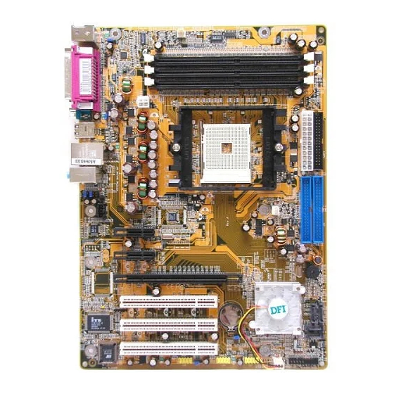
Page 4: System Board Layout
Quick Setup Guide Chapter 1 - Quick Setup Guide System Board Layout... -
Page 5: Clear Cmos Data
Jumpers Clear CMOS Data PS/2 Power Select Important: The 5VSB power source of your power supply must support 720mA. Quick Setup Guide 1-2 On: Normal 2-3 On: (default) Clear CMOS Data 1-2 On: 5V 2-3 On: 5VSB (default) -
Page 6: Usb Power Select
Quick Setup Guide USB Power Select Important: If you are using the Wake-On-USB Keyboard/Mouse function for 2 USB ports, the 5VSB power source of your power supply must support 1.5A. For 3 or more USB ports, the 5VSB power source of your power supply must support 2A. -
Page 7: Rear Panel I/O Ports
Rear Panel I/O Ports PS/2 Parallel Mouse PS/2 S/PDIF-in S/PDIF-out I/O Connectors S/PDIF-out/in and CD-in Connectors S/PDIF-out S/PDIF-in Left audio channel Ground Ground Right audio channel CD-in Note: DO NOT use RCA S/PDIF and optical S/PDIF at the same time. Quick Setup Guide USB 1-2 USB 3-4 Line-in... -
Page 8: Universal Serial Bus Ports
Quick Setup Guide Universal Serial Bus Ports USB 2 USB 1 USB 4 USB 3 FDD and IDE Connectors USB 5-6 USB 9-10 USB 7-8 IDE 2 IDE 1... -
Page 9: Audio (Rear Audio And Front Audio)
Audio (Rear Audio and Front Audio) Rear audio Line-in Line-out Mic-in 2-channel Light Blue Line-in Lime Line-out Pink Mic-in PCI Express Slots PCI Express x1 PCI Express x1 PCI Express x16 Quick Setup Guide Front audio 6-channel 4-channel Rear R/L Rear R/L Front R/L Front R/L... -
Page 10: Serial Ata Connectors
Quick Setup Guide Serial ATA Connectors Important: Before creating RAID, make sure you have installed the Serial/Parallel ATA drives and connected the data cables otherwise you won’t be able to enter the NVIDIA RAID BIOS utility. SATA 1 SATA 2 (J11) (J13) SATA 4... -
Page 11: Irda Connector
IrDA Connector IRRX Ground N. C. IRTX Note: The sequence of the pin functions on some IR cable may be reversed from the pin function defined on the system board. Make sure to connect the cable connector to the IR connector according to their pin functions. -
Page 12: Power Connectors
Quick Setup Guide LEDs DRAM Power LED Standby Power LED Power Connectors +12V Ground Ground +12V Important: To ensure that adequate power is provided, we strongly recommend that you use a minimum of 400 Watt (or greater) power supply. 1 3 1 +3.3VDC +3.3VDC -12VDC... -
Page 13: Front Panel Connectors
Front Panel Connectors HD-LED (Primary/Secondary IDE LED) Reserved ATX-SW (ATX power switch) Reserved RESET (Reset switch) SPEAKER (Speaker connector) PWR-LED (Power/Standby LED) Quick Setup Guide ATX-SW PWR-LED HD-LED SPEAKER RESET Pin Assignment HDD LED Power N. C. N. C. PWRBT+ PWRBT- N.
Need help?
Do you have a question about the nF4X Infinity and is the answer not in the manual?
Questions and answers