Table of Contents
Advertisement
Advertisement
Table of Contents
Troubleshooting

Related Manuals for DFI Infinity NF-ULTRA-M2


Summary of Contents for DFI Infinity NF-ULTRA-M2
-
Page 1: System Board
System Board User’s Manual 935-NF4UM1-000G 92510626... - Page 2 Copyright This publication contains information that is protected by copyright. No part of it may be reproduced in any form or by any means or used to make any transformation/adaptation without the prior writ- ten permission from the copyright holders. This publication is provided for informational purposes only.
-
Page 3: Fcc And Doc Statement On Class B
FCC and DOC Statement on Class B This equipment has been tested and found to comply with the limits for a Class B digital device, pursuant to Part 15 of the FCC rules. These limits are designed to provide reasonable protection against harmful interference when the equipment is operated in a residential installation. -
Page 4: Table Of Contents
Table of Contents About this Manual................Warranty....................Registering the Product............... Static Electricity Precaution..............Safety Measures..................About the Package................Before Using the System Board............Chapter 1 - Introduction..............Specifications........................... Features.............................. Français..............................Deutsch............................... Español..............................Ðóññêèé ÿçûê......................... Japanese............................. Chapter 2 - Hardware Installation............ System Board Layout ...................... -
Page 5: About This Manual
About this Manual An electronic file of this manual is included in the CD. To view the user’s manual, insert the CD into a CD-ROM drive. The autorun screen (Mainboard Utility CD) will appear. Click the “TOOLS” icon then click “Manual” on the main menu. Warranty 1. -
Page 6: Registering The Product
Introduction Registering the Product We encourage you to register your DFI product online. DFI’s product registration service entitles you to notifications about product updates, special discounts and/or promotional offers; and puts your licensing information on file so that we may efficiently assist you if in any case needed. - Page 7 Introduction 3. The DFI Product Registration page will appear. Click Next to continue. 4. Select or fill in the necessary information to complete the registration. 5. Thank you for registering your DFI product.
-
Page 8: Static Electricity Precaution
Introduction Static Electricity Precautions It is quite easy to inadvertently damage your PC, system board, components or devices even before installing them in your system unit. Static electrical discharge can damage computer components without causing any signs of physical damage. You must take extra care in handling them to ensure against electrostatic build-up. -
Page 9: About The Package
Introduction About the Package The system board package contains the following items. If any of these items are missing or damaged, please contact your dealer or sales representative for assistance. One system board One IDE cable One floppy cable Two Serial ATA data cables One Serial ATA power cable One I/O shield One RAID driver diskette... -
Page 10: Chapter 1 - Introduction
Introduction Chapter 1 - Introduction Specifications ® Processor • AMD Athlon 64 X2 / Athlon 64 FX / Athlon 64 / Sempron • Socket AM2 Front Side Bus • 2000MT/s HyperTransport interface Chipset • NVIDIA nForce4 Ultra (INFINITY NF ULTRA-M2) NVIDIA nForce4 (INFINITY NF-M2) System Memory... - Page 11 Introduction IDE with NVIDIA • Supports two IDE connectors that allow connecting up to four RAID UltraDMA 133Mbps hard drives • NVIDIA RAID allows RAID arrays spanning across Serial ATA and Parallel ATA • RAID 0, RAID 1, RAID 0+1 and JBOD Serial ATA with •...
-
Page 12: Features
Introduction Features The system board supports the AMD Athlon 64 X2 / Athlon 64 FX / Athlon 64 / Sempron processor for Socket AM2. AMD Athlon provides superior computing for many software applications by al- lowing both 32-bit and 64-bit applications to run simultaneously on the same platform. - Page 13 Introduction CPU Overheat Protection has the capability of CPU Overheat Protection monitoring the CPU’s temperature during sys- tem boot up. Once the CPU’s temperature exceeded the temperature limit pre-defined by the CPU, the system will automatically shutdown. This preventive measure has been added to protect the CPU from damage and insure a safe computing envi- ronment.
- Page 14 Introduction S/PDIF is a standard audio file transfer format that trans- fers digital audio signals to a device without having to be converted first to an analog format. This prevents the quality of the audio signal from degrading whenever it is converted to analog.
- Page 15 Introduction The system board is equipped with an IrDA connector IrDA for wireless connectivity between your computer and peripheral devices. The IRDA (Infrared Data Association) specification supports data transfers of 115K baud at a distance of 1 meter. The system board supports USB 2.0 and USB 1.1 ports.
- Page 16 Introduction This function allows you to use a USB key- Wake-On-USB board or USB mouse to wake up a system from the S3 (STR - Suspend To RAM) state. Important: If you are using the Wake-On-USB Keyboard/Mouse function for 2 USB ports, the 5VSB power source of your power supply must support ≥...
-
Page 17: Français
Introduction Français Caractéristiques et Spécifications ® Processeur • AMD Athlon 64 X2 / Athlon 64 FX / Athlon 64 / Sempron • Socket AM2 • Interface HyperTransport 2000MT/s Chipset • NVIDIA nForce4 Ultra (INFINITY NF ULTRA-M2) NVIDIA nForce4 (INFINITY NF-M2) Mémoire Système •... - Page 18 Introduction • Supporte des disques durs jusqu’à UltraDMA 133Mbps IDE avec NVIDIA • NVIDIA RAID permet des ensembles RAID sur toute l’étendue RAID du port de série ATA et du parallèle ATA • RAID 0, RAID 1, RAID 0+1 et JBOD •...
-
Page 19: Deutsch
Introduction Deutsch Leistungsmerkmale und Technische Daten ® Prozessor • AMD Athlon 64 X2 / Athlon 64 FX / Athlon 64 / Sempron • Socket AM2 • Interface HyperTransport 2000MT/s Chipset • NVIDIA nForce4 Ultra (INFINITY NF ULTRA-M2) NVIDIA nForce4 (INFINITY NF-M2) Systemspeicher •... - Page 20 Introduction IDE mit NVIDIA • Unterstützung der Festplatten bis zum UltraDMA 133Mbps RAID • NVIDIA RAID ermöglicht, dass die RAID-Arrays sowohl serielle als auch parallele ATA-Schnittstellen umfassen. • RAID 0, RAID 1, RAID 0+1 und JBOD Serial ATA mit RAID •...
-
Page 21: Español
Introduction Español Características y Especificaciones ® Procesador • AMD Athlon 64 X2 / Athlon 64 FX / Athlon 64 / Sempron • Socket AM2 • Interface de HyperTransport 2000MT/s Chipset • NVIDIA nForce4 Ultra (INFINITY NF ULTRA-M2) NVIDIA nForce4 (INFINITY NF-M2) Memoria de Sistema •... - Page 22 Introduction IDE con NVIDIA • Soporta las unidades duras hasta de UltraDMA 133Mbps RAID • NVIDIA RAID permite RAID órdenes atravesando Serial ATA y Parallel ATA • RAID 0, RAID 1, RAID 0+1 y JBOD Serial ATA con • 4 ports de Serial ATA RAID •...
-
Page 23: Ðóññêèé Ÿçûê
Introduction Ðóññêèé ÿçûê Ðóññêèé ÿçûê Ðóññêèé ÿçûê Ðóññêèé ÿçûê Ðóññêèé ÿçûê Õàðàêòåðèñòèêè è ñâîéñòâà Õàðàêòåðèñòèêè è ñâîéñòâà Õàðàêòåðèñòèêè è ñâîéñòâà Õàðàêòåðèñòèêè è ñâîéñòâà Õàðàêòåðèñòèêè è ñâîéñòâà Ïðîöåññîð Ïðîöåññîð Ïðîöåññîð Ïðîöåññîð Ïðîöåññîð • AMD Athlon 64 X2 / Athlon 64 FX / Athlon 64 / ®... - Page 24 Introduction L A N L A N L A N L A N L A N •Realtek RTL8111 Gigabit PCIE LAN • Ïîääåðæêà IEEE 802.3 (10BASE-T), 802.3u (100BASE- TX) è 802.3ab (1000BASE-T) IDE c NVIDIA IDE c NVIDIA IDE c NVIDIA IDE c NVIDIA IDE c NVIDIA •...
-
Page 25: Japanese
Introduction... - Page 26 Introduction...
-
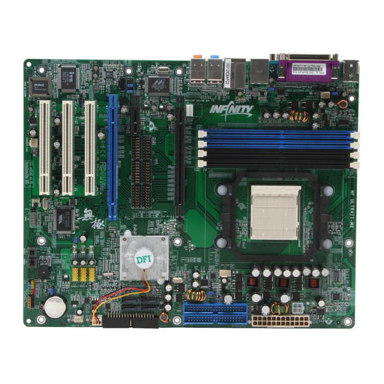
Page 27: Chapter 2 - Hardware Installation
Hardware Installation Chapter 2 - Hardware Installation System Board Layout INFINITY NF ULTRA-M2... - Page 28 Hardware Installation INFINITY NF-M2...
-
Page 29: System Memory
Hardware Installation Warning: Electrostatic discharge (ESD) can damage your system board, processor, disk drives, add-in boards, and other components. Perform the upgrade instruction procedures described at an ESD workstation only. If such a station is not available, you can provide some ESD protection by wearing an antistatic wrist strap and attaching it to a metal part of the system chassis. -
Page 30: Hardware Installation
Hardware Installation The system board supports the following memory interface. Single Channel (SC) Data will be accessed in chunks of 64 bits (8B) from the memory channels. Dual Channel (DC) Data will be accessed in chunks of 128 bits from the memory channels. - Page 31 Hardware Installation DDR2 Speed in Relation to the CPU’s Core Multiplier The DDR2 speed is highly relevant to the CPU’s core multiplier. It varies in accordance to the DRAM speed set in the BIOS (Genie BIOS Setting, “DRAM Speed” field) and the CPU’s core multiplier. Core Core Multiplier...
-
Page 32: Installing The Dim Module
Hardware Installation BIOS Setting Configure the system memory in the Genie BIOS Setting submenu (“DRAM Timing and Config section) of the BIOS. Installing the DIM Module A DIM module simply snaps into a DIMM socket on the system board. Pin 1 of the DIM module must correspond with Pin 1 of the socket. -
Page 33: Cpu
Hardware Installation Overview The system board is equipped with Socket AM2 for installing an AMD CPU designed for this socket. Installing the CPU 1. Make sure the PC and all other peripheral devices connected to it has been powered down. 2. - Page 34 Hardware Installation 4. Unlock the socket by pushing the lever sideways, away from the socket, then lifting it up to a 90 angle. Make sure the lever is lifted to at least this angle otherwise the CPU will not fit in properly. Lever 5.
- Page 35 Hardware Installation 6. Insert the CPU into the socket until it is seated in place. The CPU will fit in only one orientation and can easily be inserted without exerting any force. Important: Do not force the CPU into the socket. Forcing the CPU into the socket may bend the pins and damage the CPU.
- Page 36 Hardware Installation Installing the Fan and Heat Sink The CPU must be kept cool by using a CPU fan with heat sink. Without sufficient air circulation across the CPU and heat sink, the CPU will overheat damaging both the CPU and system board. The fan / heat sink assembly must provide airflow adequate to en- sure appropriate internal temperature and cooling of the compo- nents in the system.
- Page 37 Hardware Installation 2. The system board comes with the retention module base already installed. Retaining Retention module base 3. Place the heat sink on top of the CPU. Now hook one side of the retention clip onto the retention module base by fitting the hole(s) on the retention clip into the retaining tab(s) of the reten- tion module base.
- Page 38 Hardware Installation 4. Hook the other side of the retention clip so that the hole(s) on the retention clip also fit into the retaining tab(s) of the retention module base. 5. Move the retention lever to its opposite side then push it down to lock the fan and heat sink assembly to the retention module base.
-
Page 39: Jumper Settings
Hardware Installation Jumper Settings Clear CMOS Data 1-2 On: Normal 2-3 On: (default) Clear CMOS Data If you encounter the following, a) CMOS data becomes corrupted. b) You forgot the supervisor or user password. c) You are unable to boot-up the computer system because the processor’s ratio/clock was incorrectly set in the BIOS. - Page 40 Hardware Installation 4. After powering-on the system, press <Del> to enter the main menu of the BIOS. 5. Select the Genie BIOS Setting submenu and press <Enter>. 6. Set the processor’s ratio/clock to its default setting or an appro- priate setting. Refer to the Genie BIOS Setting section in chapter 3 for more information.
- Page 41 Hardware Installation PS/2 Power Select 1-2 On: 5V 2-3 On: 5VSB (default) JP7 is used to select the power of the PS/2 keyboard/mouse port. Selecting 5VSB will allow you to use the PS/2 keyboard or PS/2 mouse to wake up the system. BIOS Setting Configure the PS/2 keyboard/mouse wake up function in the Power Management Setup submenu of the BIOS.
-
Page 42: Usb Power Select
Hardware Installation USB Power Select USB 1-4 (JP5) 1-2 On: 5V 2-3 On: 5VSB (default) USB 5-10 (JP6) 1-2 On: 5V 2-3 On: 5VSB (default) JP5 and JP6 are used to select the power of the USB ports. Selecting 5VSB will allow you to use the USB keyboard or USB mouse to wake up the system.. - Page 43 Hardware Installation CPU Fan Select JP11 2-3 On: 1-2 On: 4-pin CPU fan 3-pin CPU fan The system board allows connecting a CPU fan that comes with a 3-pin or 4-pin cable connector. Set JP11 according to the type of cable connector that you are using.
-
Page 44: Rear Panel I/O Ports
Hardware Installation Rear Panel I/O Ports PS/2 Parallel Mouse 1394-1 Line-in Line-out Mic-in PS/2 S/PDIF-in USB 1-2 USB 3-4 S/PDIF-out The rear panel I/O ports consist of the following: • PS/2 mouse port • PS/2 keyboard port • Parallel Port •... - Page 45 Hardware Installation PS/2 Mouse and PS/2 Keyboard Ports PS/2 Mouse PS/2 Keyboard The system board is equipped with an onboard PS/2 mouse (Green) and PS/2 keyboard (Purple) ports - both at location CN2 of the system board. The PS/2 mouse port uses IRQ12. If a mouse is not connected to this port, the system will reserve IRQ12 for other expansion cards.
-
Page 46: Parallel Port
Hardware Installation Parallel Port Parallel The system board has a standard parallel port (Burgundy) at loca- tion CN8 for interfacing your PC to a parallel printer. It supports SPP, ECP and EPP. Setting Function Allows normal speed operation but (Standard Parallel Port) in one direction only. - Page 47 Hardware Installation S/PDIF S/PDIF-out S/PDIF-in SPDIF out SPDIF in Optical S/PDIF The system board is equipped with an onboard RCA S/PDIF-out jack and a RCA S/PDIF-in jack at locations CN5 and CN7 respec- tively. It is also equipped with a connector at location J3 for optical S/PDIF connection.
-
Page 48: Com Port
Hardware Installation COM Port The system board is equipped with an onboard serial port at loca- tion CN1. The serial port is RS-232 asynchronous communication port with 16C550A-compatible UARTs that can be used with mo- dems, serial printers, remote display terminals, and other serial de- vices. - Page 49 Hardware Installation IEEE 1394 1394-1 1394-2 The system board is equipped with an onboard IEEE 1394 port at location CN3 (IEEE 1394-1) of the system board. It is also equipped with an IEEE 1394 connector at location J8 (1394-2) for connecting an additional 1394 device. The 1394 port may come mounted on a card-edge bracket.
-
Page 50: Universal Serial Bus Ports
Hardware Installation Universal Serial Bus Ports USB 2 USB 1 USB 4 USB 3 USB 7-8 USB 9-10 USB 5-6 The system board supports 10 USB 2.0/1.1 ports. USB allows data exchange between your computer and a wide range of simultaneously accessible external Plug and Play peripherals. - Page 51 Hardware Installation Driver Installation You may need to install the proper drivers in your operating system to use the USB device. Refer to your operating system’s manual or documentation for more information. Refer to chapter 4 for more information about installing the USB 2.0 driver.
-
Page 52: Rj45 Lan Port
Hardware Installation RJ45 LAN Port The onboard LAN port is at location CN4 of the system board. LAN allows the system board to connect to a local area network by means of a network hub. BIOS Setting Configure the onboard LAN in the Integrated Peripherals submenu (“Onboard Device”... - Page 53 Hardware Installation Audio Rear audio Line-in Line-out Mic-in Front audio Rear Panel Audio (CN6) Line-in (Light Blue) This jack is used to connect any audio devices such as Hi-fi set, CD player, tape player, AM/FM radio tuner, synthesizer, etc. Line-out (Lime) This jack is used to connect to the front right and front left speakers of the audio system.
- Page 54 Hardware Installation Front Audio The front audio connector at location J4 allows you to connect to the line-out and mic-in jacks that are at the front panel of your system. Using this connector will disable the rear audio’s line-out and mic-in functions.
-
Page 55: Internal I/O Connectors
Hardware Installation I/O Connectors CD-in Internal Audio Connector Left audio channel Ground Ground Right audio channel The CD-in connector at location J1 is used to receive audio from a CD-ROM drive, TV tuner or MPEG card. -
Page 56: Floppy Disk Drive Connector
Hardware Installation Floppy Disk Drive Connector The system board is equipped with a floppy disk drive connector that supports two standard floppy disk drives. To prevent improper floppy cable installation, the floppy disk header has a keying mecha- nism. The 34-pin connector on the floppy cable can be placed into the header only if pin 1 of the connector is aligned with pin 1 of the header. -
Page 57: Serial Ata Connectors
Hardware Installation Serial ATA Connectors SATA 1 SATA 2 (J11) (J13) SATA 4 (J10) SATA 3 (J2) • SATA speed up to 3Gb/s (INFINITY NF ULTRA-M2) SATA speed up to 1.5Gb/s (INFINITY NF-M2) • RAID 0, RAID 1, RAID 0+1 and JBOD •... -
Page 58: Ide Disk Drive Connector
Hardware Installation IDE Disk Drive Connector IDE 2 IDE 1 • NVIDIA RAID allows RAID arrays spanning across Serial ATA and Parallel ATA • RAID 0, RAID 1, RAID 0+1 and JBOD The system board is equipped with two shrouded PCI IDE headers that will interface four Enhanced IDE (Integrated Drive Electronics) disk drives. - Page 59 Hardware Installation If you are adding a third or fourth IDE device, use another IDE cable and install one end of the cable into the IDE 2 header (J22) on the system board and the other connectors to the IDE devices. Note: Refer to your disk drive user’s manual for information about selecting proper drive switch settings.
-
Page 60: Irda Connector
Hardware Installation IrDA Connector IRRX Ground N. C. IRTX Connect the cable connector from your IrDA module to the IrDA connector (J5). Note: The sequence of the pin functions on some IrDA cable may be reversed from the pin function defined on the system board. Make sure to connect the cable connector to the IrDA connector according to their pin functions. -
Page 61: Cooling Fan Connectors
Hardware Installation Cooling Fan Connectors Ground Power Sense Speed Control CPU fan Ground Power Sense System fan Ground N. C. Power Chipset fan Connect the CPU fan’s cable connector to the CPU fan connector (J30) on the system board. Chipset fan (J32) and System fan (J31) are used to connect additional cooling fans. -
Page 62: Standby Power Led
Hardware Installation Standby Power LED Standby Power LED Standby Power LED This LED will light when the system is in the standby mode. Warning: When the Standby Power LED lit red, it indicates that power is present on the PCI slots. Power-off the PC then unplug the power cord prior to installing any add-in cards. -
Page 63: Power Connectors
Hardware Installation Power Connectors Use a power supply that complies with the ATX12V Power Supply Design Guide Version 1.1. An ATX12V power supply unit has a standard 24-pin ATX main power connector that must be inserted onto CN10. 1 2 2 4 +3.3VDC +12VDC +5VDC... - Page 64 Hardware Installation The system board requires a minimum of 300 Watt power supply to operate. Your system configuration (CPU power, amount of memory, add-in cards, peripherals, etc.) may exceed the minimum power requirement. To ensure that adequate power is provided, we strongly recommend that you use a minimum of 400 Watt (or greater) power supply.
- Page 65 Hardware Installation Restarting the PC Normally, you can power-off the PC by: 1. Pressing the power button at the front panel of the chassis. 2. Pressing the power switch that is on the system board (note: not all system boards come with this switch). If for some reasons you need to totally cut off the power supplied to the PC, switch off the power supply or unplug the power cord.
-
Page 66: Front Panel Connectors
Hardware Installation Front Panel Connectors ATX-SW PWR-LED HD-LED SPEAKER RESET HD-LED: Primary/Secondary IDE LED This LED will light when the hard drive is being accessed. RESET: Reset Switch This switch allows you to reboot without having to power off the system thus prolonging the life of the power supply or system. - Page 67 Hardware Installation PWR-LED: Power/Standby LED When the system’s power is on, this LED will light. When the system is in the S1 (POS - Power On Suspend) or S3 (STR - Suspend To RAM) state, it will blink every second. Note: If a system did not boot-up and the Power/Standby LED did not light after it was powered-on, it may indicate that the CPU...
- Page 68 Hardware Installation PCI Express Slots PCI Express x1 PCI Express x1 PCI Express x16 PCI Express x16 Install PCI Express x16 graphics card, that comply to the PCI Ex- press specifications, into the PCI Express x16 slot. To install a graph- ics card into the x16 slot, align the graphics card above the slot then press it down firmly until it is completely seated in the slot.
- Page 69 Hardware Installation Battery The lithium ion battery powers the real-time clock and CMOS memory. It is an auxiliary source of power when the main power is shut off. Safety Measures • Danger of explosion if battery incorrectly replaced. • Replace only with the same or equivalent type recommend by the manufacturer.
-
Page 70: Chapter 3 - Bios Setup
BIOS Setup Chapter 3 - BIOS Setup Award BIOS Setup Utility The Basic Input/Output System (BIOS) is a program that takes care of the basic level of communication between the processor and pe- ripherals. In addition, the BIOS also contains codes for various ad- vanced features found in this system board. -
Page 71: Standard Cmos Features
BIOS Setup Standard CMOS Features Use the arrow keys to highlight “Standard CMOS Features” and press <Enter>. A screen similar to the one below will appear. Phoenix - AwardBIOS CMOS Setup Utility Standard CMOS Features Date <mm:dd:yy> Tue, Jun 6 2006 Item Help Time <hh:mm:ss>... -
Page 72: Bios Setup
BIOS Setup IDE Channel 0 Master/Slave, IDE Channel 1 Master/Slave and IDE Chan- nel 2/3/4/5 Master IDE Channel 0 Master IDE Channel 0 Slave Used to configure Parallel ATA drives IDE Channel 1 Master IDE Channel 1 Slave IDE Channel 2 Master IDE Channel 3 Master Used to configure Serial ATA drives IDE Channel 4 Master... - Page 73 BIOS Setup To configure the IDE drives, move the cursor to a field then press <Enter>. The following screen will appear. Phoenix - AwardBIOS CMOS Setup Utility IDE Channel 0 Master IDE HDD Auto-Detection Press Enter Item Help IDE Channel 0 Master Menu Level Auto Access Mode...
- Page 74 BIOS Setup Capacity Displays the approximate capacity of the disk drive. Usually the size is slightly greater than the size of a formatted disk given by a disk checking program. Cylinder This field displays the number of cylinders. Head This field displays the number of read/write heads. Precomp This field displays the number of cylinders at which to change the write timing.
- Page 75 BIOS Setup Halt On This field determines whether the system will stop if an error is detected during power up. The default setting is All Errors. No Errors The system boot will not stop for any errors detected. All Errors The system boot will stop whenever the BIOS detects a non-fatal error.
-
Page 76: Advanced Bios Features
BIOS Setup Advanced BIOS Features The Advanced BIOS Features allows you to configure your system for basic operation. Some entries are defaults required by the system board, while others, if enabled, will improve the performance of your system or let you set some features according to your preference. Phoenix - AwardBIOS CMOS Setup Utility Advanced BIOS Features Item Help... -
Page 77: Removable Device Priority
BIOS Setup Removable Device Priority This field is used to select the boot sequence of the removable devices. Move the cursor to this field then press <Enter>. Use the Up or Down arrow keys to select a device then press <+> to move it up or <->... -
Page 78: Hard Disk Boot Priority
BIOS Setup Hard Disk Boot Priority This field is used to select the boot sequence of the hard drives. Move the cursor to this field then press <Enter>. Use the Up or Down arrow keys to select a device then press <+> to move it up or <->... -
Page 79: Network Boot Priority
BIOS Setup Network Boot Priority This field is used to select the boot sequence of the network. Move the cursor to this field then press <Enter>. Use the Up or Down arrow keys to select a device then press <+> to move it up or <- >... - Page 80 BIOS Setup Virus Warning This field protects the boot sector and partition table of your hard disk drive. When this field is enabled, the Award BIOS will monitor the boot sector and partition table of the hard disk drive. If an attempt is made to write to the boot sector or partition table of the hard disk drive, the BIOS will halt the system and an error message will appear.
- Page 81 BIOS Setup Boot Up Floppy Seek When enabled, the BIOS will check whether the floppy disk drive in- stalled is 40 or 80 tracks. Note that the BIOS cannot distinguish be- tween 720K, 1.2M, 1.44M and 2.88M drive types as they are all 80 tracks.
- Page 82 BIOS Setup Security Option This field determines when the system will prompt for the password - everytime the system boots or only when you enter the BIOS setup. Set the password in the Set Supervisor/User Password submenu. System The system will not boot and access to Setup will be denied unless the correct password is entered at the prompt.
- Page 83 BIOS Setup Full Screen Logo Show This field is applicable only if you want a particular logo to appear during system boot-up. Enabled The logo will appear in full screen during system boot- Disabled The logo will not appear during system boot-up. Small Logo(EPA) Show Enabled The EPA logo will appear during system boot-up.
-
Page 84: Advanced Chipset Features
BIOS Setup Advanced Chipset Features Phoenix - AwardBIOS CMOS Setup Utility Advanced Chipset Features Enabled SSE/SSE2/SSE3 Instructions Item Help System BIOS Cacheable Disabled Menu Level SLI Broadcast Aperture Disabled ↑↓→← : Move Enter: Select +/-/PU/PD: Value F10: Save ESC: Exit F1: General Help F5: Previous Values F6: Fail-Safe Defaults... - Page 85 BIOS Setup SLI Broadcast Aperture To enhance SLI’s performance, set this field to Auto. However, en- hanced performance is supported only if you are using NVIDIA graphics driver version 7.84 or later. If you are using an older ver- sion, you must disable this function otherwise you may encounter problems.
-
Page 86: Integrated Peripherals
BIOS Setup Integrated Peripherals Phoenix - AwardBIOS CMOS Setup Utility Integrated Peripherals OnChip IDE Device Press Enter Item Help Onboard Device Press Enter Menu Level Press Enter Super IO Device ↑↓→← : Move Enter: Select +/-/PU/PD: Value F10: Save ESC: Exit F1: General Help F5: Previous Values F6: Fail-Safe Defaults... - Page 87 BIOS Setup OnChip IDE Channel0 and OnChip IDE Channel1 These fields allow you to enable or disable the primary and second- ary IDE controller. The default is Enabled. Select Disabled if you want to add a different hard drive controller. Primary Master/Slave PIO and Secondary Master/Slave PIO PIO means Programmed Input/Output.
- Page 88 BIOS Setup IDE Prefetch Mode This allows data and addresses to be stored in the internal buffer of the chip, thus reducing access time. Enable this field to achieve better performance. IDE HDD Block Mode Enabled The IDE HDD uses the block mode. The system BIOS will check the hard disk drive for the maximum block size the system can transfer.
-
Page 89: Onboard Device
BIOS Setup Onboard Device Phoenix - AwardBIOS CMOS Setup Utility Onboard Device OnChip USB V1.1+V2.0 Item Help USB Keyboard Support Disabled Menu Level Auto AC97 Audio ↑↓→← : Move Enter: Select +/-/PU/PD: Value F10: Save ESC: Exit F1: General Help F5: Previous Values F6: Fail-Safe Defaults F7: Optimized Defaults... -
Page 90: Super Io Device
BIOS Setup Super IO Device Phoenix - AwardBIOS CMOS Setup Utility Super IO Device Onboard FDC Controller Enabled Item Help Onboard Serial Port 1 3F8/IRQ4 Menu Level 2F8/IRQ3 Onboard Serial Port (IR) IR Mode Select IrDA IR Duplex Mode Half 378/IRQ7 Onboard Parallel Port Parallel Port Mode... - Page 91 BIOS Setup IR Mode Select This field is used to select the type of IrDA standard supported by your IrDA device. For better transmission of data, your IrDA periph- eral device must be within a 30 angle and within a distance of 1 meter.
-
Page 92: Power Management Setup
BIOS Setup Power Management Setup The Power Management Setup allows you to configure your system to most effectively save energy. Phoenix - AwardBIOS CMOS Setup Utility Power Management Setup ACPI Function Enabled Item Help ACPI Suspend Type S1(POS) Menu Level Power Management User Define HDD Power Down... - Page 93 BIOS Setup Power Management This field allows you to select the type (or degree) of power saving by changing the length of idle time that elapses before the “HDD Power Down” field is activated. Min Saving Minimum power saving time for the “HDD Power Down”...
- Page 94 BIOS Setup Wake Up On LAN Set this field to Enabled to wake up the system via the onboard LAN or via a LAN card that uses the PCI PME (Power Manage- ment Event) signal to remotely wake up the system. Access to the LAN card will cause the system to wake up.
- Page 95 BIOS Setup Power On Function This field allows you to use the PS/2 keyboard or PS/2 mouse to power-on the system. Button only Default setting. Uses the power button to power on the system. Hot Key Select the function key you would like to use to power-on the system in the “Hot Key Power On”...
-
Page 96: Resources Controlled By
BIOS Setup PnP/PCI Configurations This section describes configuring the PCI bus system. It covers some very technical items and it is strongly recommended that only experienced users should make any changes to the default settings. Phoenix - AwardBIOS CMOS Setup Utility PnP/PCI Configurations Resources Controlled By Auto... -
Page 97: Irq Resources
BIOS Setup IRQ Resources Move the cursor to this field and press <Enter>. This field is used to set each system interrupt to either Reserved or PCI Device. Phoenix - AwardBIOS CMOS Setup Utility IRQ Resources IRQ-3 assigned to PCI Device Item Help IRQ-4 assigned to PCI Device... -
Page 98: Pc Health Status
BIOS Setup PC Health Status Phoenix - AwardBIOS CMOS Setup Utility PC Health Status Shutdown Temperature C/185 Item Help Shutdown TEMP (Chipset) C/194 Menu Level AUTO CPU Fan Power AUTO Chip Fan Power System Fan Power AUTO VCC3 Voltage 3.29V +12V Voltage 11.90V 5V Standby Voltage... -
Page 99: Genie Bios Setting
BIOS Setup Important: The maximum operating temperature of an AMD CPU is 70 C while the maximum operating temperature of the NVIDIA chipset is 90 Refer to the PC Health Status or the Smart Guardian utility for the current CPU and chipset temperatures. Ensure that the CPU and chipset temperatures does not exceed 60 C and 80 C respectively... -
Page 100: Dram Configuration
BIOS Setup DRAM Configuration Move the cursor to this field and press <Enter>. The following screen will appear. Phoenix - AwardBIOS CMOS Setup Utility DRAM Configuration Item Help 1T/2T Memory Timing Auto CAS# Latency (Tcl) Auto Menu Level DDRII Timing Item Disabled x TwTr Command Delay 3 bus clocks... - Page 101 BIOS Setup CAS# Latency (Tcl) This field is used to select the clock cycle of the CAS latency time. The option selected specifies the timing delay before SDRAM starts a read command after receiving it. DDRII Timing Item The options are Enabled and Disabled. TwTr Command Delay The options are Reserved, 1 bus clock, 2 bus clocks and 3 bus clocks.
- Page 102 BIOS Setup (Trrd) RAS to RAS Delay This field is used to select the delay time from RAS (Row Address Strobe) to the next RAS (Row Address Strobe) when reading to the same bank. The lesser the clock cycle, the faster the DRAM’s per- formance.
- Page 103 BIOS Setup Bottom of [31:24] IO Space This field is used to select the memory that will be remapped to another address higher than 00E0. DRAM ECC Enable This field is used to enable or disable the DRAM’s ECC feature. When enabled, it allows the system to automatically correct and re- cover from memory failure.
- Page 104 BIOS Setup AMD K8 Cool ‘n’ Quiet Control Auto Enables AMD’s Cool‘n’Quiet technology. This function allows the system to detect the CPU’s tasks and utili- zation status. When the CPU’s task slows down, the system effectively lowers power consumption by changing its CPU speed and voltage, subsequently decreasing its noise level.
- Page 105 BIOS Setup CPU Voltage Setting This field allows you to manually adjust to a higher core voltage that is supplied to the CPU. DRAM Voltage Setting This field allows you to manually select higher voltage supplied to the DRAM. Chip Voltage Setting This field allows you to manually select higher voltage supplied to the north bridge chip.
- Page 106 BIOS Setup Init Display First PCIEx-Master When the system boots, it will first initialize the PCI Express Master graphics card. PCIEx-Slave When the system boots, it will first initialize the PCI Express Slave graphics card. PCI Slot When the system boots, it will first initialize PCI. CPU Spread Spectrum The options are Disabled and Center Spread.
-
Page 107: Hot Keys
BIOS Setup Hot Keys Clearing the CMOS Data If the overclocked settings resulted to the system’s instability or worse yet, not being able to boot up the system, you can clear the CMOS data during system boot up by using the Insert key and power/reset button. -
Page 108: Load Fail-Safe Defaults
BIOS Setup Load Fail-Safe Defaults The “Load Fail-Safe Defaults” option loads the troubleshooting de- fault values permanently stored in the ROM chips. These settings are not optimal and turn off all high performance features. You should use these values only if you have hardware problems. Highlight this option in the main menu and press <Enter>. -
Page 109: Load Optimized Defaults
BIOS Setup Load Optimized Defaults The “Load Optimized Defaults” option loads optimized settings from the BIOS ROM. Use the default values as standard values for your system. Highlight this option in the main menu and press <Enter>. Phoenix - AwardBIOS CMOS Setup Utility Standard CMOS Features Genie BIOS Setting Advanced BIOS Features... -
Page 110: Set Supervisor Password
BIOS Setup Set Supervisor Password If you want to protect your system and setup from unauthorized entry, set a supervisor’s password with the “System” option selected in the Advanced BIOS Features. If you want to protect access to setup only, but not your system, set a supervisor’s password with the “Setup”... -
Page 111: Set User Password
BIOS Setup Set User Password If you want another user to have access only to your system but not to setup, set a user’s password with the “System” option se- lected in the Advanced BIOS Features. If you want a user to enter a password when trying to access setup, set a user’s password with the “Setup”... -
Page 112: Save & Exit Setup
BIOS Setup Save & Exit Setup When all the changes have been made, highlight “Save & Exit Setup” and press <Enter>. Phoenix - AwardBIOS CMOS Setup Utility Standard CMOS Features Genie BIOS Setting Advanced BIOS Features Load Fail-Safe Defaults Advanced Chipset Features Load Optimized Defaults Integrated Peripherals Set Supervisor Password... -
Page 113: Exit Without Saving
BIOS Setup Exit Without Saving When you do not want to save the changes you have made, high- light “Exit Without Saving” and press <Enter>. Phoenix - AwardBIOS CMOS Setup Utility Standard CMOS Features Genie BIOS Setting Advanced BIOS Features Load Fail-Safe Defaults Advanced Chipset Features Load Optimized Defaults... -
Page 114: Nvraid Bios
BIOS Setup NVRAID BIOS The NVRAID BIOS utility is used to configure and manage RAID on Serial ATA drives and Parallel ATA drives. After you power up the system and all drives have been detected, the NVRAID BIOS status message screen will appear. Press the <F10>... -
Page 115: Updating The Bios
Updating the BIOS To update the BIOS, you will need the new BIOS file and a flash utility, AWDFLASH.EXE. You can download them from DFI’s web site or contact technical support or your sales representative. 1. Save the new BIOS file along with the flash utility AWDFLASH.EXE to a floppy disk. - Page 116 BIOS Setup 6. The following will appear. Do You Want to Save BIOS (Y/N) This question refers to the current existing BIOS in your system. We recommend that you save the current BIOS and its flash utility; just in case you need to reinstall the BIOS. To save the current BIOS, press <Y>...
-
Page 117: Chapter 4 - Supported Softwares
Supported Software Chapter 4 - Supported Software Drivers, Utilities and Software Applications The CD that came with the system board contains drivers, utilities and software applications required to enhance the performance of the system board. Inser t the CD into a CD-ROM drive. The autorun screen (Mainboard Utility CD) will appear. - Page 118 Supported Software Microsoft DirectX 9.0C When you insert the CD, the default menu that will appear is the Chipset Drivers menu. If in any case it is not, click the “CHIPSET” icon that is on the left side of the autorun screen. 1.
- Page 119 Supported Software 3. You are now ready to install DirectX. Click Next. 4. Click Finish. Reboot the system for DirectX to take effect.
- Page 120 Supported Software nVidia Chipset Drivers On the left side of the autorun screen, click the “CHIPSET” icon. 1. Click “nVidia Chipset Drivers” on the main menu. 2. The installation wizard will install NVIDIA Windows nForce Drivers on your computer. Click Next to continue.
- Page 121 Supported Software 4. Setup is currently installing the drivers. 5. Read the information about the NVIDIA IDE software driver then click Next. 6. Follow the prompts on the screen to complete installation. Click “Yes, I want to restar t my computer now”...
-
Page 122: Realtek Audio Drivers
Supported Software Realtek Audio Drivers On the left side of the autorun screen, click the “AUDIO” icon. 1. Click “Realtek Audio Drivers” on the main menu. 2. The installation wizard will extract the files needed to install AC97 audio. 3. AC97 audio is intalling and configuring the new software installation. - Page 123 Supported Software 4. Follow the prompts on the screen to complete installation. Click “Yes, I want to restar t my computer now” then click Finish. Restarting the system will allow the new software installation to take effect.
-
Page 124: Realtek Lan Drivers
Supported Software Realtek LAN Drivers On the left side of the autorun screen, click the “NETWORK” icon. 1. Click “Realtek Driver” on the main menu. 2. Setup will prepare to install the driver. 3. Follow the prompts on the screen to complete installation. - Page 125 Supported Software AMD CPU Cool‘n’Quiet Drivers On the left side of the autorun screen, click the “TOOLS” icon. 1. Click “AMD Cool‘n’Quiet Drivers” on the main menu. 2. Setup is now ready to install and configure the driver. Click Next. 3.
- Page 126 Supported Software 4. Go through the readme document for system requirements and installa- tion tips then click Next. 5. Click Next to install to the designated folder or click Browse to select another folder. 6. Click “Yes, I want to restar t my computer now”...
- Page 127 Supported Software ITE Smart Guardian The system board comes with the ITE Smart Guardian utility. This utility is capable of monitoring the system’s temperature, fan speed, voltage, etc. and allows you to manually set a range (Highest and Lowest Limit) to the items being monitored.
- Page 128 Supported Software 3. You are now ready to install Smar t Guardian. Click Next to install or click Browse to select another folder. 4. Click Next to add the program icon to the Program Folder. 5. Click Finish. Reboot the system for the driver to take effect.
-
Page 129: Installation Notes
2. All steps or procedures to install software drivers are subject to change without notice as the softwares are occassionally updated. Please go to DFI's web site at "http://www.dfi.com/support1/ download2.asp" for the latest version of the drivers or software applications. -
Page 130: Chapter 5 - Cool'n'quiet Technology
Cool‘n’Quiet Technology Chapter 5 - Cool’n’Quiet Technology Cool‘n’Quiet Technology The AMD Cool‘n’Quiet technology allows the system to detect the CPU’s tasks and utilization status. When the CPU’s task slows down, the system effectively lowers power consumption by lowering its CPU speed and voltage, subsequently decreasing its noise level. To enable the Cool‘n’Quiet technology, the following settings are required. - Page 131 Cool‘n’Quiet Technology 4. Press <Esc> to return to the main menu of the BIOS setup utility. Select “Save & Exit Setup” and press <Enter>. 5. Type <Y> and press <Enter>. 6. Reboot the system. Install the Cool‘n’Quiet Driver 1. Insert the provided CD into a CD-ROM drive. 2.
- Page 132 Cool‘n’Quiet Technology Step 3: Configure Power Management in Windows 1. On the Windows desktop, click Start then select Control Panel. 2. In Control Panel, double-click the Power Options icon. 3. In the Power Schemes tab, select Minimal Power Management under the Power schemes section then click OK.
-
Page 133: Chapter 6 - Raid
RAID Chapter 6 - RAID The system board supports NVIDIA RAID (Redundant Array of Independent Disk) that allows RAID arrays spanning across 4 Serial ATA and Parallel ATA drives. It supports RAID 0, RAID 1, RAID 0+1 and JBOD. RAID Levels RAID 0 (Striped Disk Array without Fault Tolerance) RAID 0 uses two new identical hard disk drives to read and write data in parallel, interleaved stacks. - Page 134 RAID Settings To enable the RAID function, the following settings are required. 1. Connect Serial/Parallel ATA drives. 2. Configure Serial/Parallel ATA in the Award BIOS. 3. Configure RAID in the NVRAID BIOS 4. Install RAID driver. Step 1: Connect Serial/Parallel ATA Drives IDE connectors SATA connectors Refer to chapter 2 for details on connecting the serial/parallel ATA...
- Page 135 RAID Step 2: Configure Serial/Parallel ATA in the Award BIOS 1. Power-on the system then press <Del> to enter the main menu of the Award BIOS. 2. Select the Integrated Peripherals submenu - “OnChip IDE Device” section of the BIOS. 3.
- Page 136 RAID Step 3: Configure RAID in the RAID BIOS When the system powers-up and all drives have been detected, the NVRAID BIOS status message screen will appear. Press the <F10> key to enter the utility. The utility allows you to build a RAID system on Serial ATA drives and Parallel ATA drives.
- Page 137 RAID This time, select “NVIDIA nForce4 ATA RAID Class Controller”. Press <Enter> to install the driver. Make sure both files have been installed or the setup will fail. If you need to install other devices, please do so at this time otherwise please proceed to the next step.
-
Page 138: Appendix A - System Error Message
System Error Message Appendix A - System Error Message When the BIOS encounters an error that requires the user to correct something, either a beep code will sound or a message will be displayed in a box in the middle of the screen and the message, PRESS F1 TO CONTINUE, CTRL-ALT-ESC or DEL TO ENTER SETUP, will be shown in the information box at the bottom. - Page 139 System Error Message setting than indicated in Setup. Determine which setting is correct, either turn off the system and change the jumper or enter Setup and change the VIDEO selection. FLOPPY DISK(S) fail (80) Unable to reset floppy subsystem. FLOPPY DISK(S) fail (40) Floppy type mismatch.
-
Page 140: Appendix B - Troubleshooting
Troubleshooting Appendix B - Troubleshooting Troubleshooting Checklist This chapter of the manual is designed to help you with problems that you may encounter with your personal computer. To efficiently troubleshoot your system, treat each problem individually. This is to ensure an accurate diagnosis of the problem in case a problem has multiple causes. -
Page 141: Power Supply
Troubleshooting The picture seems to be constantly moving. 1. The monitor has lost its vertical sync. Adjust the monitor’s vertical sync. 2. Move away any objects, such as another monitor or fan, that may be creating a magnetic field around the display. 3. -
Page 142: Hard Drive
Troubleshooting Hard Drive Hard disk failure. 1. Make sure the correct drive type for the hard disk drive has been entered in the BIOS. 2. If the system is configured with two hard drives, make sure the bootable (first) hard drive is configured as Master and the sec- ond hard drive is configured as Slave. -
Page 143: Troubleshooting
Troubleshooting 3. Verify that the attached serial device works by attaching it to a serial port that is working and configured correctly. If the serial device does not work, either the cable or the serial device has a problem. If the serial device works, the problem may be due to the onboard I/O or the address setting.
Need help?
Do you have a question about the Infinity NF-ULTRA-M2 and is the answer not in the manual?
Questions and answers