
Related Manuals for Kramer RC-IR2


Summary of Contents for Kramer RC-IR2
-
Page 1: User Manual
Kramer Electronics, Ltd. USER MANUAL Model: RC-IR2 Infrared Remote Control Device Remote Control Transmitter Remote Receiver... -
Page 2: Table Of Contents
Configuration Initializing the RC-IR2 7.2.1 Assigning the ROUTER Number 7.2.2 Assigning the GROUP Number Using the RC-IR2 keys in the ROUTER Mode 7.3.1 The <0/10> Selector Key 7.3.2 Switching an Input to an Output 7.3.3 The STO and RCL Keys 7.3.3.1 Storing an Input/Output Configuration... - Page 3 Figure 4: VP-23N Switcher Selector Buttons Figure 5: VP-26 Switcher Selector Buttons Tables Table 1: RC-IR2 Remote Control Transmitter Features Table 2: RC-IR2 Initializing Sequence Table 3: Group Definition Specifications for Older Machines Table 4: Group Definition Criteria for Older Machines...
-
Page 4: Introduction
3 Download up-to-date Kramer user manuals from the Internet at this URL: http://www.kramerelectronics.com 4 For example, when ordering an RC-IR2 remote control transmitter, order an external remote receiver to control Kramer switchers such as the VP-4x4 that has no built-in remote receiver... -
Page 5: Overview
Overview Overview The high performance Kramer RC-IR2 is an upgrade of the popular RC-IR1, with additional functionality that lets you control Kramer scalers as well as switchers. The RC-IR2: Is a hand held infrared remote control transmitter that includes the... -
Page 6: Your Rc-Ir2 Remote Control Transmitter
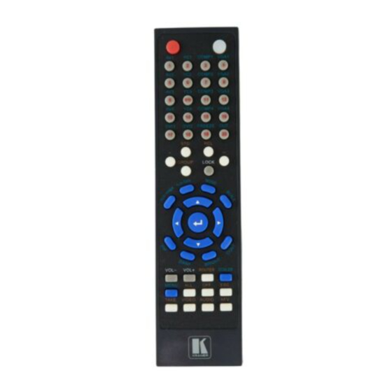
Your RC-IR2 Remote Control Transmitter Your RC-IR2 Remote Control Transmitter Figure 1 and Table 1 define the RC-IR2 remote control transmitter: The red LED lights POWER:Cycles power when sending instructions Button colors key: WHITE Routers/Switchers GRAY General BLUE Scalers Figure 1: RC-IR2 Remote Control Transmitter... -
Page 7: Table 1: Rc-Ir2 Remote Control Transmitter Features
Your RC-IR2 Remote Control Transmitter Table 1: RC-IR2 Remote Control Transmitter Features Keys Function Selector ROUTER Mode 20 buttons for selecting the channels, the group, the machine number, machine type and so on (see section 7) Buttons SCALER Source 18 source selector keys: AV1, AV2, AV3, AV4, YC1, YC2, YC3, YC4, COMP1,... -
Page 8: Your Remote Receiver
1 Some switchers do not have a built-in remote receiver. For these units, an external remote receiver may be connected to the switcher. When ordering an RC-IR2 remote control transmitter, a separate order must be made for an external remote receiver... -
Page 9: Figure 3: Connecting The External Remote Receiver
To connect the external remote receiver, as the example in Figure 3 illustrates, do the following: 1. Connect the external remote receiver to the RS-232 port on the Kramer switcher, via one of the following methods: A direct one-to-one connection, by simply connecting the attached RS-232 cable’s 9-pin D-sub connector to the RS-232 9-pin D-sub... -
Page 10: Using The Rc-Ir2 Remote Control Transmitter
10 seconds will necessitate restarting that action. The General (Gray) Keys The RC-IR2 includes a power ON button, a red transmission LED, which illuminates when pressing any key, as well as: Selector buttons, which operate differently for the ROUTER mode and the... -
Page 11: The Router Mode Keys
Initialize the RC-IR2 (see section 7.2) Use the ROUTER Mode keys (see section 7.3) 7.1 Configuration For the RC-IR2 to identify the switcher that it has to control, a ROUTER number (see section 7.2.1) and a GROUP number (see section 7.2.2) need to be assigned for specific identification of each switcher. -
Page 12: Initializing The Rc-Ir2
7.2.1 Assigning the ROUTER Number To assign the switcher’ s machine number to the RC-IR2, do the following: 1. Point the remote control transmitter at the remote receiver and press the ROUTER key. 2. Press the digit corresponding to the machine number This sets and saves the ROUTER number on the RC-IR2. -
Page 13: Table 3: Group Definition Specifications For Older Machines
VS-1002, VS-1202; VS-1602, VS-1604, VS-1604YC 1 Old protocol 2 New Kramer Protocol-2000 (version 3.1) 3 Use a cross connection (or Null-modem adapter), as section 5.2 of the user manual: IR-1 and IR-1-01 describes 4 When operating the VS-1211 unit, in group 12 (but not group 15), press the (input) # key twice... -
Page 14: Using The Rc-Ir2 Keys In The Router Mode
Groups 1, 2, 3, 5, 6, 15, 17, and 18 Groups 4, 12, 14, and 16 7.3 Using the RC-IR2 keys in the ROUTER Mode The following sections describe how to: Use the <-> and <--> keys for selecting the single or the double digit modes (see section 7.3.1) -
Page 15: Switching An Input To An Output
1 When switching units categorized in group 11 and in groups 1, 2, 3, 4, 14, 15 and 16, ignore step 1 which is inapplicable to units with just one output 2 Check the switcher’ s user manual to determine the number of configurations you can store. For example for the VP-66ETH, you can store up to six configurations KRAMER: SIMPLE CREATIVE TECHNOLOGY... -
Page 16: The Take Key
Pressing an OUT-IN combination implements the switch immediately No protection is offered to allow the correction of an erroneous action before it is implemented The TAKE key on RC-IR2 can be used regardless of the state of the TAKE button on the switcher. 7.3.4.1... -
Page 17: Controlling A Presentation Switcher
VP-23N and the VP-23RC, see section 7.4.1 VP-26, see section 7.4.2 7.4.1 Controlling the VP-23N via the RC-IR2 You can control the VP-23N Presentation Switcher using the RC-IR2 to do the following: Switch inputs to outputs (see section 7.4.1.1) Adjust the volume (see section 7.4.1.2) 7.4.1.1... -
Page 18: Adjusting The Volume Of The Vp-23N
Adjusting the Volume of the VP-23N of the VP-23N using the You can increase and/or decrease the volume RC-IR2 remote control transmitter. Increasing the Volume of the VP-23N The volume level on the VP-23N Presentation Switcher can be adjusted separately for the audio output of each individual switcher, as well as for the microphone input and the Master audio output. -
Page 19: Controlling The Vp-26 Via The Rc-Ir2
7.4.2 Controlling the VP-26 via the RC-IR2 You can control the VP-26 Presentation Switcher using the RC-IR2 to do the following: Switch inputs to outputs (see section 7.4.2.1) Adjust the volume (see section 7.4.2.2) 7.4.2.1... -
Page 20: Adjusting The Volume Of The
Table 8) to switch an input to the Master Audio Output. 7.4.2.2 Adjusting the Volume of the VP-26 of the VP-26 using the RC-IR2 You can increase and/or decrease the volume remote control transmitter. Increasing the Volume of the VP-26... -
Page 21: Controlling An Expanded Series 16X16 Matrix Switcher
7.5 Controlling an Expanded Series 16x16 Matrix Switcher You can control an expanded series 16x16 matrix switcher, using the RC-IR2. For example, when using two VS-1616V units to form a 32x16 , set both VS-1616V units as MACHINE # 1 switcher . -
Page 22: Operating In The Scaler Mode
SCALER functions; other functions can only be accessed via the OSD menu keys. To recognize a Kramer machine when operating in the Scaler Mode, using the RC-IR2, point the remote control transmitter at the remote receiver and do the following: 1. Press the SCALER key. - Page 23 EXCLUSION OF DAMAGES The liability of Kramer for any effective products is limited to the repair or replacement of the product at our option. Kramer shall not be liable for: 1. Damage to other property caused by defects in this product, damages based upon inconvenience, loss of use of the product, loss of time, commercial loss;...
- Page 24 For the latest information on our products and a list of Kramer distributors, visit our Web site: www.kramerelectronics.com, where updates to this user manual may be found. We welcome your questions, comments and feedback. Safety Warning: Disconnect the unit from the power supply before opening/servicing.
Need help?
Do you have a question about the RC-IR2 and is the answer not in the manual?
Questions and answers