Summary of Contents for Kramer Cobra R500-2
-
Page 1: User Manual
Kramer Electronics, Ltd. USER MANUAL Models: Cobra R500A, Video-Audio receiver Cobra R500-2, Video-RS-232 receiver... -
Page 2: Table Of Contents
Table 1: Cobra R500A / Cobra R500-2 Configuration Settings Table 2: Cable Length EQ Settings Table 3: HD15 Video Connector PINOUT Table 4: T568B CAT 5 PINOUT Table 5: 1/8” (3.5 mm) Audio/Serial Connection (model dependent) Table 6: Technical Specifications of the Cobra R500A, Cobra R500-2 Contents... -
Page 3: Introduction
2 Download up-to-date Kramer user manuals from the Internet at this URL: http://www.kramerelectronics.com 3 The complete list of Kramer cables is on our Web site at http://www.kramerelectronics.com 4 In addition, you may also need 1/8” (3.5mm) audio cable with RCA jacks, 1/8” (3.5mm) serial cable with DB9 connector,... -
Page 4: Overview
(often associated with low quality cables) Avoiding interference from neighboring electrical appliances that may adversely influence signal quality and positioning your Cobra R500A / R500-2 in a location free from moisture and away from excessive sunlight and dust Caution... -
Page 5: Setup And Installation
4.1 Making the Connections This section contains figures showing connections with the specific Cobra R500A / R500-2 series models. In general, however, the connection and setup procedure at both transmitter and receiver ends is as follows: At the transmitter end (refer to the transmitter user guide): 1. -
Page 6: Connections On The Vga/Audio Transmitter
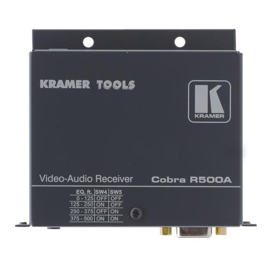
The single-port units with audio support video and audio signals over CAT 5 cable. The audio signal is line-level audio, and powered speakers are required. Figure 1 shows the Kramer Cobra transmitter with Audio Transmitter connections, and Figure 2 shows the Kramer Cobra R500A Video-Audio receiver. -
Page 7: Connections On The Video/Serial Transmitter
The serial signal is 3 wire TX, RX, GND serial. Figure 3 shows the Kramer Cobra transmitter with serial Transmitter connections, and Figure 4 shows the Cobra R500-2 Video-RS-232 receiver. See Appendix A for cable pinouts of the Cobra R500-2. -
Page 8: Configuration Settings
All Models 4.5 Video Adjustment The only adjustments required on the Cobra R500A and Cobra R500-2 are the SW positions 4 and 5 which must be set to compensate for cable length. Using the table below as a guide, turn SW positions ON or OFF for best... -
Page 9: Solutions To Common Problems
5 switches, or CAT 5 distribution amps, the serial signal is a unidirectionally broadcast mode only. In this mode, all other Cobra CAT5 Video System devices must be the simplex serial type. Cobra R500-2 use 3 wire (TX,RX,GND) signals only via the 1/8” connector (see Appendix A for pinout) Problem: “Green shift”... -
Page 10: Table 3: Hd15 Video Connector Pinout
Solutions to Common Problems RGBS RGsB Composite SVHS Red + Red + Green+ Green+ Blue+ Blue+ — — Red- Red- Green- Green- Blue- Blue- — — — — — — C Sync — — — — KRAMER: SIMPLE CREATIVE TECHNOLOGY (Y/C) -
Page 11: Table 4: T568B Cat 5 Pinout
Signal Serial Tx (DB9 pin3) Left Audio+ Ring Serial Rx (DB9 pin2) Right Audio+ Sleeve Serial GND (DB9 pin5) Note: The stereo audio input at the transmitter is summed and output as mono audio on both channels at the receiver. -
Page 12: Technical Specifications
WEIGHT: 1 Specifications are subject to change without notice Technical Specifications of the Cobra R500A, Cobra R500-2 Category 5, 5e, 6 shielded or unshielded twisted pair CE; FCC Class A, IC Class/class A To UXGA (1600x1200 @ 60Hz), RGBHV, RGB, Composite, s-Video, Component Video modes At 500 ft. - Page 14 For the latest information on our products and a list of Kramer distributors, visit our Web site: www.kramerelectronics.com, where updates to this user manual may be found. We welcome your questions, comments and feedback. Safety Warning: Disconnect the unit from the power supply before opening/servicing.


Need help?
Do you have a question about the Cobra R500-2 and is the answer not in the manual?
Questions and answers