
Subscribe to Our Youtube Channel
Related Manuals for Kramer Cobra R1300A


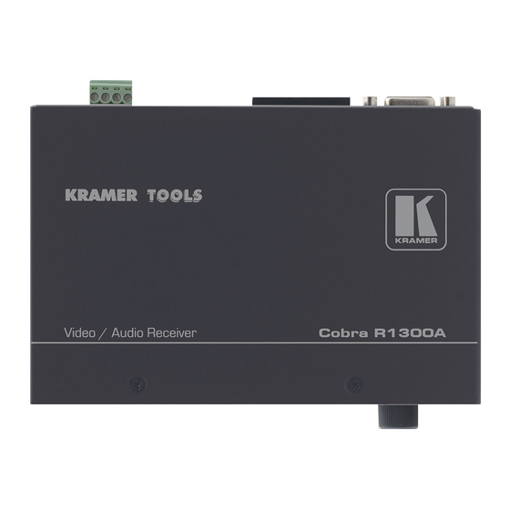
Summary of Contents for Kramer Cobra R1300A
-
Page 1: User Manual
Kramer Electronics, Ltd. USER MANUAL Models: Cobra R1300A, Video / Audio Receiver Cobra R1300S2, Universal Receiver... -
Page 2: Table Of Contents
Figure 6: Skew Module Tables Table 1: HD15 Video Connector PINOUT Table 2: Terminal Block Connection Table 3: HD15 Video Connector PINOUT Table 4: T568B CAT5 PINOUT Table 5: Configuration Jumper Settings Table 6: Technical Specifications of the Cobra R1300A, Cobra R1300S2... -
Page 3: Introduction
Receiver and/or Cobra R1300S2 Universal Receiver. The Kramer Cobra Series System extends video, audio and serial signals over ordinary Category 5 cable. This manual covers the Cobra R1300A Video / Audio Receiver, and the Cobra R1300S2 Universal Receiver. These units are field configurable for various video, audio and serial options. -
Page 4: Getting Started
R1300S2 in a location free from moisture and away from excessive sunlight and dust 1 The complete list of Kramer cables is on our Web site at http://www.kramerelectronics.com 2 In addition, you may also need audio cable with RCA jacks, serial cable with DB9 connectors, and video cable with HD15... - Page 5 Overview Caution – No operator-serviceable parts inside unit. Warning – Use only the Kramer Electronics input power wall adapter that is provided with this unit Warning – Disconnect power and unplug unit from wall before installing or removing device or servicing unit.
-
Page 6: Setup And Installation
3. Apply power. The LED should light and video should appear on the display (make sure that the display is powered ON). 4. Adjust video levels and skew compensation. 5. Mount the R1300A / R1300S2 in a location that ensures the ventilation holes and fan are not blocked. KRAMER: SIMPLE CREATIVE TECHNOLOGY... -
Page 7: Connections On The Single-Port Vga/Audio
You can also use the transmitters and receivers to make video-only connections without audio. Figure 1 shows the Single-Port Cobra CAT5 Video System with Audio Transmitter connections, and Figure 2 shows the receiver connections. Figure 1: Transmitter Connections Figure 2: Cobra R1300A Video / Audio Receiver Connections... -
Page 8: Connections On The Single-Port Vga S2
Audio is full stereo, line level. One or two separate channels of mono audio may also be used. See the Figures below for cabling connections. Figure 3: Transmitter Connections Figure 4: Cobra R1300S2 Universal Receiver Connections KRAMER: SIMPLE CREATIVE TECHNOLOGY... -
Page 9: Video Adjustment
Setup and Installation 4.5 Video Adjustment 4.5.1 Cable Distance Compensation Settings To get the highest quality video signals from your Cobra CAT5 Video System, follow the instructions and diagrams below: NOTE: TURN KNOB SLOWLY DURING ADJUSMENT PROCEDURE. Turning too fast may result in missing the proper EQ setting resulting in picture loss. To Reset EQ and Skew values to 0, remove power from R1300A / R1300S2, Push and hold EQ/Skew Knob in and re-apply power. -
Page 10: Solutions To Common Problems
In this mode, all other Cobra CAT5 Video System devices must be the simplex serial type. The last device in a transmitter or daisy chain configuration must be terminated. The termination switch is located on the front of the unit. KRAMER: SIMPLE CREATIVE TECHNOLOGY... - Page 11 Solutions to Common Problems Problem: “Green shift” or “green washout” on multimedia signals. Solution: The standard video/serial model is designed to function with DC coupled signals in which the black level is referenced to 0 volts. Nearly all VGA cards function this way. Some media servers, however, provide AC coupled signals and can cause a green color shift in the video.
-
Page 12: Table 1: Hd15 Video Connector Pinout
Note: Typically Channel 1 is left audio and Channel 2 is right audio. * series RECEIVER units use Channel 1 for Right audio and channel 2 for left audio. * series TRANSMITTER units use Channel 2 for Right audio and channel 1 for left audio. KRAMER: SIMPLE CREATIVE TECHNOLOGY... -
Page 13: Table 3: Hd15 Video Connector Pinout
Solutions to Common Problems Appendix A Cabling Pinouts Table 3: HD15 Video Connector PINOUT Full Duplex 3 wire (SA/SAP) Simplex Ground Ground Ground Table 4: T568B CAT5 PINOUT... - Page 14 Solutions to Common Problems Appendix B Configuration Settings Note: the Cobra R1300A Video and the Audio Receiver Cobra R1300S2 Universal Receiver are typically pre-configured at time of order and will have factory configuration indicated on the bottom of the unit. The factory configuration may be changed or checked by using the following jumper location diagram as well as Table 5 for jumper settings.
-
Page 15: Table 5: Configuration Jumper Settings
Solutions to Common Problems Table 5: Configuration Jumper Settings Configuration Option (all options utilize 4th pair): RGBHV Computer Video (see note below on daisy chaining) With Left/Right Line Level Audio OFF OFF OFF With SDPIF Digital Audio OFF OFF OFF OFF With Simplex Serial (receive only) OFF OFF OFF OFF With Composite Video... - Page 16 Solutions to Common Problems Appendix D Setting Sync Mode The Cobra R1300A / R1300S2 has the capability for fixed and agile sync. The default sync mode setting is for agile sync which replicates the source sync polarity signals. However some displays require a fixed sync polarity that is not possible to change at the video source.
-
Page 17: Figure 6: Skew Module
Solutions to Common Problems Appendix E Skew Module The Cobra R1300A / R1300S2 receivers have an optional skew compensation module that can be installed or removed. To install the skew compensation module: 1. Remove top cover. 2. Remove the 3 jumpers from J16 pins 1-2, 4-5, 7-8. -
Page 18: Technical Specifications
Technical Specifications Technical Specifications Table 6: Technical Specifications of the Cobra R1300A, Cobra R1300S2 CABLE REQUIRED: Category 5, 5e, 6 shielded or unshielded twisted pair COMPLIANCE: CE; FCC Class A, IC Class/class A VIDEO SUPPORT: all supported VESA modes to WUXGA (1920x1200), RGBHV, RGB,... - Page 20 For the latest information on our products and a list of Kramer distributors, visit our Web site: www.kramerelectronics.com, where updates to this user manual may be found. We welcome your questions, comments and feedback. Safety Warning: Disconnect the unit from the power supply before opening/servicing.
Need help?
Do you have a question about the Cobra R1300A and is the answer not in the manual?
Questions and answers