
Related Manuals for Kramer TOOLS TP-46


Summary of Contents for Kramer TOOLS TP-46
-
Page 1: User Manual
Kramer Electronics, Ltd. USER MANUAL Models: TP-45, Component/XGA – Audio Transmitter TP-46, Component/XGA – Audio Receiver... -
Page 2: Table Of Contents
Your TP-46 Component/XGA – Audio Receiver Connecting a Component/XGA – Audio Distribution System Connecting TP-45 and TP-46 in the XGA Mode Connecting TP-45 and TP-46 in the Component Video Mode Wiring the CAT5 LINE IN / LINE OUT RJ-45 Connectors Technical Specifications Figures Figure 1: TP-45 Component/XGA –... -
Page 3: Introduction
Congratulations on purchasing your Kramer TOOLS TP-45 Component/XGA – Audio Transmitter and Kramer TOOLS TP-46 Component/XGA – Audio Receiver. The TP-45 and TP-46 are suitable for utilizing existing UTP cabling that results in an efficient, fast and uncluttered environment for: Presentation and multimedia applications... - Page 4 SELECT button to ANALOG AUDIO TP-45 Analog Audio ANALOG AUDIO S/PDIF S/PDIF Getting Started Plasma Display Connect the Output to the TP-46 DVD Player Plasma Display Connect to DVD Player the next TP-46 unit Connect the power TP-46 Analog Audio and/or S/PDIF...
-
Page 5: Overview
4 And audio signal 5 By releasing the video SELECT button 6 You can connect up to three additional TP-46 units, adding a total cable length of up to 300 meters. The video quality may be reduced if further units are connected... -
Page 6: About The Power Connect Feature
1 Also known as Y, Cb, Cr, or Y, B-Y, R-Y, or Y, Pb, Pr 2 It is recommended to power the receiver (TP-46) when connecting just one power adapter 3 CAT5 cable is still suitable for the video/audio transmission, but not for feeding the power at these distances... -
Page 7: Shielded Twisted Pair (Stp) / Unshielded Twisted Pair (Utp)
(often associated with low quality cables) Avoid interference from neighboring electrical appliances and position your TP-45/TP-46 away from moisture, excessive sunlight and dust Caution Warning wall adapter that is provided with this unit Warning before installing or removing device or servicing unit. -
Page 8: Your Component/Xga - Audio Transmitter And Receiver
Your Component/XGA – Audio Transmitter and Receiver This section describes the: TP-45 Component/XGA – Audio Transmitter, see section 4.1 TP-46 Component/XGA – Audio Receiver, see section 4.2 4.1 Your TP-45 Component – S/PDIF Line Transmitter Figure 1, Figure 2 and Table 1 define the TP-45: Figure 1: TP-45 Component/XGA –... -
Page 9: Figure 3: Tp-45 Component/Xga - Audio Transmitter (Underside)
2 By default, both switches are set to NORM Function Connect to the XGA source Connect to the LINE IN connector on the TP-46 +12V DC connector for powering the unit Connect to the stereo analog audio source Connect to the digital audio source... -
Page 10: Your Tp-46 Component/Xga - Audio Receiver
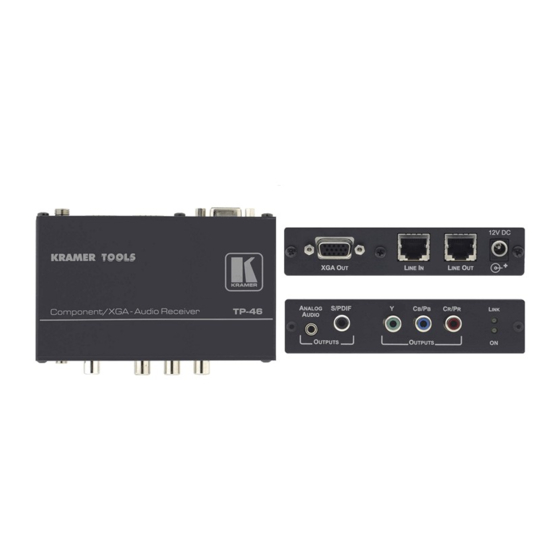
Your Component/XGA – Audio Transmitter and Receiver 4.2 Your TP-46 Component/XGA – Audio Receiver Figure 4, Figure 5 and Table 3 define the TP-46: Figure 4: TP-46 Component/XGA – Audio Receiver Figure 5: TP-46 (Top Side and Lower Side Panels) -
Page 11: Figure 6: Tp-46 Component/Xga - Audio Receiver (Underside)
Y RCA Connector RCA Connector RCA Connector ON LED LINK LED Figure 6 and Table 4 define the underside of the TP-46: Figure 6: TP-46 Component/XGA – Audio Receiver (Underside) Table 4: TP-46 Component/XGA – Audio Receiver (Underside) Features Feature LEVEL Trimmer... -
Page 12: Connecting A Component/Xga - Audio Distribution System
Release the audio SELECT button to choose ANALOG AUDIO 1 You can connect up to three additional TP-46 units, adding a total cable length of up to 300 meters. The video quality may be reduced if further units are connected... - Page 13 1 Alternatively, you can connect a digital audio acceptor to the S/PDIF RCA connector, or you can connect both 2 If you cannot connect the power to both the TP-45 and TP-46, you can just connect the power to the TP-46...
-
Page 14: Connecting Tp-45 And Tp-46 In The Component Video Mode
Source Figure 7: Component/XGA – Audio Distribution System, XGA Mode 5.2 Connecting TP-45 and TP-46 in the Component Video Mode To configure a TP-45/TP-46 Component/XGA – Audio distribution system component video mode, as the example in Figure 8 illustrates, do the following: 1. - Page 15 2 Alternatively, you can connect an analog audio acceptor, or you can connect both 3 If you cannot connect the power to both the TP-45 and TP-46, connect it to the TP-46 only. If more than one TP-46 is connected, connect the power to each TP-46 unit...
-
Page 16: Figure 8: Component/Xga - Audio Distribution System, Component Video Mode
Connecting a Component/XGA – Audio Distribution System Plasma Display Plasma Display Figure 8: Component/XGA – Audio Distribution System, Component Video Mode To the next TP-46 unit DVD Player KRAMER: SIMPLE CREATIVE TECHNOLOGY... -
Page 17: Wiring The Cat5 Line In / Line Out Rj-45 Connectors
Connecting a Component/XGA – Audio Distribution System 5.3 Wiring the CAT5 LINE IN / LINE OUT RJ-45 Connectors Table 5 and Figure 9 define the CAT5 PINOUT, using a straight pin-to-pin cable with RJ-45 connectors: Table 5: CAT5 PINOUT EIA /TIA 568A Wire Color Green / White Green... -
Page 18: Technical Specifications
TP-45: 1 Stereo analog audio, 0dBu/50k , 0.5V/75 , on a 3.5mm jack 1 digital S/PDIF audio on an RCA connector TP-46 1 Stereo analog audio, 0dBu/1k , 0.5V/75 , on a 3.5mm jack 1 digital S/PDIF audio on an RCA connector... - Page 19 EXCLUSION OF DAMAGES The liability of Kramer for any effective products is limited to the repair or replacement of the product at our option. Kramer shall not be liable for: Damage to other property caused by defects in this product, damages based upon inconvenience, loss of use of the product, loss of time, commercial loss;...
- Page 20 For the latest information on our products and a list of Kramer distributors, visit our Web site: www.kramerelectronics.com, where updates to this user manual may be found. We welcome your questions, comments and feedback. Safety Warning: Disconnect the unit from the power supply before opening/servicing.
Need help?
Do you have a question about the TOOLS TP-46 and is the answer not in the manual?
Questions and answers