
Related Manuals for National Instruments NI PS-15


Summary of Contents for National Instruments NI PS-15
-
Page 1: Power Supply
Power Supply NI PS-15 Power Supply User Manual NI PS-15 Power Supply User Manual June 2011 372911B-01... - Page 2 11500 North Mopac Expressway Austin, Texas 78759-3504 USA Tel: 512 683 0100 For further support information, refer to the Technical Support and Professional Services appendix. To comment on National Instruments documentation, refer to the National Instruments Web site at and enter ni.com/info the Info Code feedback ©...
-
Page 3: Important Information
Warranty The NI PS-15 is warranted against defects in materials and workmanship for a period of one year from the date of shipment, as evidenced by receipts or other documentation. National Instruments will, at its option, repair or replace equipment that proves to be defective during the warranty period. - Page 4 EVALUATED OR CONTEMPLATED BY NATIONAL INSTRUMENTS, THE USER OR APPLICATION DESIGNER IS ULTIMATELY RESPONSIBLE FOR VERIFYING AND VALIDATING THE SUITABILITY OF NATIONAL INSTRUMENTS PRODUCTS WHENEVER NATIONAL INSTRUMENTS PRODUCTS ARE INCORPORATED IN A SYSTEM OR APPLICATION, INCLUDING, WITHOUT LIMITATION, THE APPROPRIATE DESIGN, PROCESS AND SAFETY LEVEL OF SUCH SYSTEM OR APPLICATION.
-
Page 5: Electromagnetic Compatibility Information
Operation of this hardware in a residential area is likely to cause harmful interference. Users are required to correct the interference at their own expense or cease operation of the hardware. Changes or modifications not expressly approved by National Instruments could void the user’s right to operate the hardware under the local regulatory rules. -
Page 6: Table Of Contents
Operation in a Sealed Enclosure..............2-7 Cooling ......................2-8 Hazardous Risks ....................2-8 Service Parts ....................2-8 Peak Current Capability ..................2-9 Charging Batteries ...................2-9 Back Feeding Loads ..................2-10 Output Circuit Breakers...................2-10 Inductive and Capacitive Loads ..............2-12 © National Instruments Corporation NI PS-15 Power Supply User Manual... - Page 7 Peak Current Capability .................. A-8 Efficiency and Power Losses..................A-8 Reliability ........................A-9 Dielectric Strength......................A-10 Used Substances ......................A-11 Environment ........................A-12 Protection Features ......................A-13 Appendix B Technical Support and Professional Services Index NI PS-15 Power Supply User Manual ni.com...
-
Page 8: About This Manual
About This Manual The NI PS-15 Power Supply User Manual describes the features and specifications of the NI PS-15 power supply and contains information about installing the power supply. Conventions The following conventions are used in this manual: » The » symbol leads you through nested menu items and dialog box options to a final action. -
Page 9: Related Documentation
Related Documentation The following documents contain information that you might find helpful as you read this manual: • NI PS-15/16/17 Side Mount Brackets Installation Guide • NI PS-15/16/17 Panel Mount Brackets Installation Guide • NI PS-15/16/17 Instruction Manual... -
Page 10: Getting Started
Printed NI PS-15/16/17 Instruction Manual Key Features The NI PS-15 includes a power reserve of 20%. This extra current may be used continuously at temperatures up to +45 °C. Additionally, the AC 100–120 V/200–240 V Auto-select input makes worldwide installation and usage very simple. -
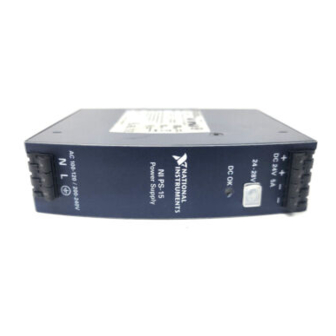
Page 11: Power Supply Description
Appendix A, Specifications. Power Supply Description Figures 1-1 and 1-2 show the functional description and front panel features of the NI PS-15 power supply. Figure 1-1 provides the functional diagram for the NI PS-15. Output Voltage Regulator... -
Page 12: Output Terminals
Figure 1-2. Front View of the NI PS-15 Power Supply Output Terminals The NI PS-15 has a total of four output terminals, providing two positive (+) output terminals and two negative (–) output terminals. Both positive terminals are wired together internally, and both negative terminals are wired together internally, as shown in Figure 1-1. -
Page 13: Output Voltage Potentiometer
The output voltage may be adjusted above 28 V by the potentiometer, but voltages beyond 28 V are not guaranteed. Output voltages greater than 28 V are not supported on an NI PS-15 unit. Note DC OK LED This green LED indicates the status of available DC power through the output terminals. -
Page 14: Mounting Equipment
PANEL MOUNTING KIT FOR NI PS-15/16/17 Side Mounting Kit The Side Mounting Kit (199429-01) allows you to mount the NI PS-15 on its side to a wall, panel surface, or a DIN-Rail for reduced installation depth. Refer to the NI PS-15/16/17 Side Mount Brackets Installation Guide for more information. -
Page 15: Installation And Configuration
Installation and Configuration This chapter describes how to prepare and operate the NI PS-15 power supply. Mounting Orientation and Installation This section describes the different mounting orientations, and the effect that mounting orientation has on power supply performance. Mounting orientations other than input terminals on the bottom and output on the top require a reduction in continuous output power or a limitation in the maximum allowed ambient temperature. - Page 16 (Horizontal ccw) Ambient Temperature 60°C Figure 2-1. NI PS-15 Mounting Orientations Mount the NI PS-15 power supply according to the installation instructions included with your mounting kit. For details on the mounting options available, refer to the Mounting Equipment section of Chapter 1, Getting Started.
-
Page 17: Wiring The Terminals
Chapter 2 Installation and Configuration Wiring The Terminals This section describes wiring for the NI PS-15 power supply. Table 2-1 provides a list of basic requirements for wiring. Table 2-1. Wiring Requirements Type Spring-Clamp Terminals Solid wire 0.5–6 mm Stranded wire 0.5–4 mm... - Page 18 Ensure that all wires are properly seated and not loose. Ensure that the rest of your equipment is ready to be powered without creating a hazard. Apply MAINS voltage to the NI PS-15 power supply. NI PS-15 Power Supply User Manual ni.com...
-
Page 19: Operating The Ni Ps-15
Chapter 2 Installation and Configuration Operating the NI PS-15 This section provides general information on the operation of the NI PS-15 power supply. Serial Operation The NI PS-15 can operate in series to increase the output voltage. Figure 2-3 shows the NI PS-15 in a serial configuration. -
Page 20: Parallel Operation
The simplest way is to put two NI PS-15 power supplies in parallel. If one power supply unit fails, the other one is automatically able to support the load current without any interruption. -
Page 21: External Input Protection
Protection section. External Input Protection The NI PS-15 power supply is tested and approved for branch circuits up to 20 A. External protection is only required if the supplying branch has an ampacity greater than 20 A. In some countries local regulations might apply, so check local codes and local requirements. -
Page 22: Cooling
However, you must not cover the ventilation grid (for example, with cable conduits) by more than 30%. Proper installation clearance for the NI PS-15 is 40 mm on top, 20 mm on the bottom, 5 mm on the left and right side when loaded permanently with full power. -
Page 23: Peak Current Capability
Output voltage dips from 24 V to 12 V. Figure 2-5. Peak Current Capacity Output Voltage Dips Charging Batteries The NI PS-15 power supply should not be used to charge batteries. © National Instruments Corporation NI PS-15 Power Supply User Manual... -
Page 24: Back Feeding Loads
Loads such as decelerating motors and inductors can feed voltage back to the power supply. This feature is also called return voltage immunity or resistance against back-EMF (Electro Magnetic Force). The NI PS-15 power supply is resistant to this and does not malfunction when a load feeds back voltage to the power supply, regardless of whether the power supply itself is on or off. - Page 25 4.0 mm 180 mΩ 5.0 m 7.0 m 10 m 15 m 25 m 40 m 270 mΩ 7.5 m 10.5 m 15 m 23 m 38 m 60 m © National Instruments Corporation 2-11 NI PS-15 Power Supply User Manual...
-
Page 26: Inductive And Capacitive Loads
270 mΩ. You should not use a wire smaller than 1.5 mm Inductive and Capacitive Loads The NI PS-15 is designed to supply any kind of load, including unlimited capacitive and inductive loads. NI PS-15 Power Supply User Manual 2-12 ni.com... -
Page 27: Dimensions And Weight
Specifications This appendix contains specifications for the NI PS-15 power supply. Specifications are subject to change without notice. Note Must be mounted in an enclosure by qualified personnel. Refer to Hazardous Voltages Figure A-1 for more information. This power supply is designed for installation in an enclosure and is intended for general use, such as in industrial control, office, communication, and instrumentation equipment. - Page 28 Appendix A Specifications 1 Suitably rated NEMA or IP enclosure that requires tool access 2 NI PS-15 Power Supply Figure A-1. NI PS-15 Power Supply 25.4 + + – – DC 24 V 5 A 24–28 V DC OK AC 100-120 / 200-240 V Depth: 117 mm (4.61 in.)
-
Page 29: Ac Input
The power factor is the ratio of the true (or real) power to the apparent power in an AC circuit. The crest factor is the mathematical ratio of the peak value to the RMS value of the input current waveform. © National Instruments Corporation NI PS-15 Power Supply User Manual... - Page 30 Figure A-3. Input Voltage Range Intput Voltage –5% Output Voltage Rise Start-up Time Delay Figure A-4. Turn On Behavior, Definitions Input Current, Typ. Output Current 1.5 2 Figure A-5. Input Current Vs. Output Load NI PS-15 Power Supply User Manual ni.com...
-
Page 31: Input Current Inrush Surge
Medium curve: Input voltage 500 V / DIV Output Voltage Lower curve: Output voltage 20 V / DIV Time scale: 100 ms / DIV Figure A-7. Input Inrush Current, Typical Behavior © National Instruments Corporation NI PS-15 Power Supply User Manual... -
Page 32: Hold-Up Time
– 5% Output Voltage Hold-up Time Figure A-9. Shutdown Behavior, Definitions Note At no load, the hold-up time can be up to several seconds. The green DC OK LED is lit during this time. NI PS-15 Power Supply User Manual ni.com... -
Page 33: Output
14 A Load impedance 200 mΩ, refer to Figure A-10 The NI PS-15 may respond with a thermal shut-down when continuously loaded with more than 120 W and operated with a MAINS voltage of 100 V or below. Output Voltage... -
Page 34: Peak Current Capability
Typical 9.1 W 8.8 W 8.2 W 2.5 A, 24 V Typical 15.3 W 14.5 W 13.2 W 5 A, 24 V Typical 19.4 W 18.2 W 16.1 W 6 A, 24 V NI PS-15 Power Supply User Manual ni.com... -
Page 35: Reliability
Reliability The lifetime expectancy shown in Table A-1 indicates the service life of the NI PS-15, and is determined by the lifetime expectancy of the built-in electrolytic capacitors. Lifetime expectancy is specified in operational hours. Lifetime expectancy is calculated according to the capacitor’s manufacturer specification. -
Page 36: Dielectric Strength
+ pole, the – pole or any other part of the output circuit should be connected to the protective earth system. This helps to avoid situations in which a load starts unexpectedly or can not be switched off when unnoticed earth faults occur. NI PS-15 Power Supply User Manual A-10 ni.com... -
Page 37: Used Substances
Input Output – Earth, PE Figure A-12. Dielectric Strength Table A-2 lists the tests that have been run to determine the NI PS-15 dielectric strength, and the results of each test. Table A-2. Dielectric Strength Test Results Test Duration Type test... -
Page 38: Environment
Above 2000 m (6500 ft), refer to Figure A-14 Over-voltage category EN 50178, altitudes up to 2000 m Altitudes from 2000 m to 6000 m Degree of pollution EN 50178, not conductive NI PS-15 Power Supply User Manual A-12 ni.com... -
Page 39: Protection Features
C... Tamb < 40 °C 2000 4000 6000 m Figure A-14. Output Current Vs. Altitude The ambient temperature is defined as the temperature 2 cm below the NI PS-15. Note Protection Features Output protection Electronically protected against overload, no-load and short-circuits... -
Page 40: Electromagnetic Compatibility
4 kV Criterion A → Surge voltage on output EN 61000-4-5 – 500 V Criterion A → +/– 500 V Criterion A Conducted disturbance EN 61000-4-6 0.15–80 MHz 10 V Criterion A NI PS-15 Power Supply User Manual A-14 ni.com... - Page 41 (2) this device must accept any interference received, including interference that may cause undesired operation. Above an average output current of 2.7 A, the harmonic current standard EN 61000-3-2 is not fulfilled. © National Instruments Corporation A-15 NI PS-15 Power Supply User Manual...
- Page 42 For EMC compliance, operate this device with shielded cabling. CE Compliance This product meets the essential requirements of applicable European Directives as follows: • 2006/95/EC; Low-Voltage Directive (safety) • 2004/108/EC; Electromagnetic Compatibility Directive (EMC) NI PS-15 Power Supply User Manual A-16 ni.com...
-
Page 43: Online Product Certification
Instruments WEEE initiatives, and compliance with WEEE Directive 2002/96/EC on Waste and Electronic Equipment, visit ni.com/environment/weee National Instruments (RoHS) National Instruments RoHS ni.com/environment/rohs_china (For information about China RoHS compliance, go to ni.com/environment/rohs_china © National Instruments Corporation A-17 NI PS-15 Power Supply User Manual... -
Page 44: Professional Services
Technical Support and Professional Services Visit the following sections of the award-winning National Instruments Web site at for technical support and professional services: ni.com • Support—Technical support at includes the ni.com/support following resources: – Self-Help Technical Resources—For answers and solutions,... - Page 45 You also can visit the Worldwide Offices section of ni.com/niglobal to access the branch office Web sites, which provide up-to-date contact information, support phone numbers, email addresses, and current events. NI PS-15 Power Supply User Manual ni.com...
- Page 46 NI resources, B-1 related documentation, ix drivers (NI resources), B-1 loads back feeding, 2-10 inductive, capacitive, 2-12 efficiency specifications, A-8 electromagnetic compatibility, A-14 enclosure, sealed operation, 2-7 © National Instruments Corporation NI PS-15 Power Supply User Manual...
- Page 47 A-8 serial, 2-5 electromagnetic compatibility, A-14 figure, 2-5 environment, A-12 two phase, 2-6 environmental management, A-17 figure, 2-6 hold-up time, A-6 output circuit breakers, 2-10 online product certification, A-17 output specifications, A-7 NI PS-15 Power Supply User Manual ni.com...
- Page 48 Index output, A-7 peak current capability, A-8 unpacking the NI PS-15 power supply, 1-1 power loss, A-8 use for charging batteries, 2-9 protection features, A-13 used substances specifications, A-11 reliability, A-9 safety, A-14 substances used, A-11 weight, A-1 Web resources, B-1...
Need help?
Do you have a question about the NI PS-15 and is the answer not in the manual?
Questions and answers