Advertisement
Quick Links
OPERATING INSTRUCTIONS
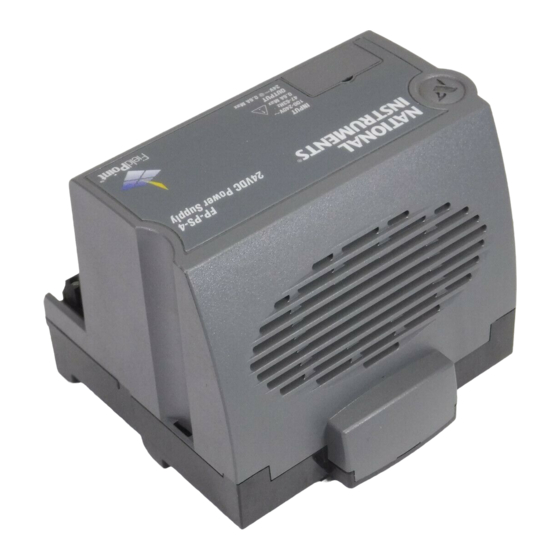
FP-PS-4
FieldPoint Power Supply
These operating instructions describe the installation, features, and
characteristics of the FP-PS-4.
Features
The FP-PS-4 is a FieldPoint power supply module with the
following features:
•
24 VDC output
•
Convenient DIN rail mounting or optional panel mounting
•
Universal AC power input: 90 to 264 VAC, 47 to 63 Hz
•
Modular FieldPoint form factor for easy integration with other
FieldPoint modules
•
15 W output for 0 to 50 °C operation
Installation
You can mount your FieldPoint system either to a DIN rail or
directly on a panel. The following sections give instructions for
both mounting methods.
Mounting Your FP-PS-4 on a DIN Rail
The FP-PS-4 power supply module has a simple rail clip for
reliable mounting onto a standard 35 mm DIN rail. Follow these
steps to mount the module on a DIN rail.
FieldPoint™, National Instruments™, NI™, and ni.com™ are trademarks of National Instruments Corporation.
Product and company names mentioned herein are trademarks or trade names of their respective companies.
323179A-01
© 2001 National Instruments Corp. All rights reserved.
November 2001
Advertisement

Summary of Contents for National Instruments FieldPoint FP-PS-4
-
Page 1: Operating Instructions
Mounting Your FP-PS-4 on a DIN Rail The FP-PS-4 power supply module has a simple rail clip for reliable mounting onto a standard 35 mm DIN rail. Follow these steps to mount the module on a DIN rail. - Page 2 1 Rail clip locked Figure 1. Unlocking the Rail Clip 2. Attach the lip on the rear of the FP-PS-4 onto the top of a 35 mm DIN rail and press it down onto the DIN rail, as shown in Figure 2.
- Page 3 3. Slide the FP-PS-4 to the desired position along the DIN rail. For maximum cooling, leave a 25 mm (1.0 in.) space between the FP-PS-4 and other devices on your DIN rail. After it is in position, lock it to the DIN rail by pushing the rail clip to the locked position, as shown in Figure 3.
- Page 4 Mounting Your FP-PS-4 on a Panel Follow these steps to install the optional FieldPoint network panel mount accessory and mount the FP-PS-4 power supply module to a panel. You can order the panel mount accessory, part number 777609-01, from National Instruments.
- Page 5 Each FP-PS-4 provides a 24 VDC output. You decide the number of FP-PS-4 modules you need in your bank based upon the specific power and isolation requirements. The total power of all of the FieldPoint modules and other devices connected to an FP-PS-4 cannot exceed the specified output for the temperature range at which you are using FP-PS-4.
- Page 6 FP-PS-4 Bank Figure 6. Wiring Power to Your FieldPoint Bank In Figure 6, the FP-PS-4 bank provides the power using both of the methods mentioned previously. The FP-2000 and FP-AO-200 have their own power supplies. Isolation is maintained because the FP-AO-200 has its own power supply.
- Page 7 Follow these steps to connect the FP-PS-4 to your FieldPoint system. 1. Use a 16 to 26 AWG stranded wire to connect the FP-PS-4 to your FieldPoint network module or I/O module. Connect the positive wire to the V terminal and the negative wire to the C terminal of the FP-PS-4.
-
Page 8: Specifications
Output voltage ... 24 VDC, nonadjusting Nominal current (I Nominal continuous power 0 to 50 °C ... 15 W 50 to 60 °C ... 10 W FP-PS-4 Operating Instructions conductor wire with 7 mm (0.275 in.) strip length as shown in Figure 8 AC fuse ) ... - Page 9 If you need to operate FieldPoint products in such an environment, the FieldPoint products must be in a suitably rated enclosure. The FP-PS-4 meets the requirements of the following standards for safety and electrical equipment for measurement, control, and laboratory use: •...
- Page 10 To obtain the DoC for this product, click Declaration of Conformity at ni.com/hardref.nsf/ Mechanical Dimensions Figure 9 shows the mechanical dimensions of the FP-PS-4. Dimensions are given in millimeters [inches]. 109.5 [4.31] 91.44 [3.60] Figure 9. Mechanical Dimensions FP-PS-4 Operating Instructions 107.19 [4.22]...
-
Page 11: Where To Go For Support
Where to Go for Support For more information about setting up your FieldPoint system, refer to these National Instruments documents: • Your FieldPoint network module user manual • Your other FieldPoint I/O module operating instructions • Your FieldPoint terminal base operating instructions Go to ni.com/support...


Need help?
Do you have a question about the FieldPoint FP-PS-4 and is the answer not in the manual?
Questions and answers