National Instruments PXIe-4112 User Manual
Hide thumbs
Also See for PXIe-4112:
- Getting started manual (14 pages) ,
- Calibration procedure (18 pages)
Table of Contents
Advertisement
Quick Links
Advertisement
Table of Contents

Related Manuals for National Instruments PXIe-4112


Summary of Contents for National Instruments PXIe-4112
- Page 1 PXIe-4112 User Manual 2024-02-05...
-
Page 2: Table Of Contents
Configure Triggers and Events..........46 Initiate the PXIe-4112 for Sourcing and Measuring......53 Acquire Measurements. - Page 3 Cleaning the PXIe-4112........
-
Page 4: Welcome To The Pxie-4112 User Manual
PXIe-4112 User Manual Welcome to the PXIe-4112 User Manual The PXIe-4112 User Manual provides detailed descriptions of product functionality and step-by-step processes for use. Looking for something else? For information not found in the User Manual for your product, like specifications or API reference, browse Related Information. -
Page 5: Pxie-4112 Overview
PXIe-4112 User Manual PXIe-4112 Overview The PXIe-4112 is a programmable precision DC power supply featuring two 60 W single quadrant channels in a single PXI express slot. The PXIe-4112 can simultaneously measure both voltage and current while supplying power. Use the PXIe-4112 for any automated test application that requires a power source with readback capabilities. - Page 6 PXIe-4112 User Manual Driver Support NI recommends that you use the newest version of the driver for your module. Table 1. Earliest Driver Version Support Driver Name Earliest Version Support NI-DCPower ni.com...
-
Page 7: Components Of A Pxie-4112 System
PXIe-4112 User Manual Components of a PXIe-4112 System The PXIe-4112 is designed for use in a system that includes other hardware components, drivers, and software. Notice A system and the surrounding environment must meet the requirements defined in PXIe-4112 Specifications. - Page 8 Cables and Accessories for recommended cables and accessories and guidance. NI-DCPower Driver Instrument driver software that provides functions to interact with the PXIe-4112 and execute measurements using the PXIe-4112. Note NI recommends to always use the most current version of NI- DCPower with the PXIe-4112.
- Page 9 NI recommends using the following cables and accessories with your module: Table 3. Cables and Accessories Accessory Description Notes Part Number Screw Terminal Connector Kit Ships with the PXIe-4112 782887-01 for PXIe-4112/3 Power Supplies Auxiliary Power Supply Module Ships with the PXIe-4112 782888-01...
- Page 10 InstrumentStudio is automatically installed when you install the NI-DCPower driver on a 64-bit system. You can access InstrumentStudio in any of the following ways: From the Windows start menu, select National Instruments » [Driver] ■ Soft Front Panel. This launches InstrumentStudio and runs a soft front panel populated with NI-DCPower devices.
- Page 11 PXIe-4112 User Manual required include and library files to your project. NI-DCPower does not ship with installed C/C++ examples. Python—For more information about installing and using Python, refer to ■ the NI-DCPower Python Documentation. © National Instruments...
-
Page 12: Pxie-4112 Theory Of Operation
The channels of the PXIe-4112 can only operate with an auxiliary DC power supply connected, which supplies 48 V. The isolated output channels can output 1 A at up to 60 V on each channel, delivering a total of 60 W maximum per channel (120 W total). - Page 13 The PXIe-4112 does not support sequence step delta time or advanced sequences. Protection There are several protection mechanisms built into the PXIe-4112 that guard against common faults. Protection mechanisms that trigger a shutdown will disable the channel output and open the output disconnect relays.
- Page 14 Isolation The output terminals of the PXIe-4112 are electrically isolated from chassis ground through a 150 V DC, Category I isolation barrier. This allows any power supply terminal to float ±150 V DC with respect to chassis ground. Each channel is also...
- Page 15 PXIe-4112 User Manual Figure 2. PXIe-4112 Block Diagram User Replacable External Power Auxiliary Protection & Filtering +48 V Power PGND PGND 150 V CAT I Reinforced Isolation Channel 0 Board Rectifier Isolated Temp and Filter Power Transformer 1 kΩ Control...
-
Page 16: Pxie-4112 Front Panel
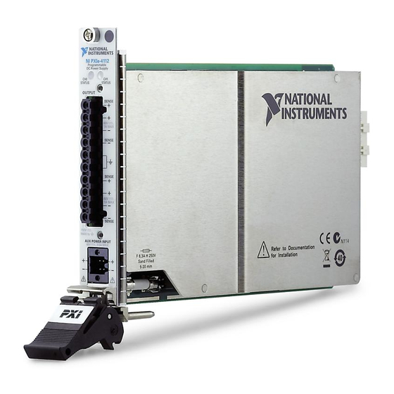
PXIe-4112 User Manual PXIe-4112 Front Panel Figure 3. PXIe-4112 Front Panel PXIe-4112 Programmable DC Power Supply STATUS STATUS OUTPUT SENSE 60 V 1A MAX SENSE SENSE 60 V 1A MAX SENSE 150V MAX to AUX POWER INPUT 3.5A MAX 1. Channel 0 Status LED 2. -
Page 17: Pxie-4112 Pinout
PXIe-4112 User Manual PXIe-4112 Pinout The following figures show the terminals on the PXIe-4112 output connector and auxiliary power input connector. Output Connector Figure 4. PXIe-4112 Output Connector Pinout Sense + CH 0 Sense Sense + CH 1 Sense Table 4. Signal Descriptions... - Page 18 Tied to chassis ground through module front panel. Use for connections to cable shields or grounding the LO force terminal. Auxiliary Power Input Connector Figure 5. PXIe-4112 Auxiliary Power Input Connector Table 5. Signal Descriptions Signal Description Terminal 0 +...
-
Page 19: Pxie-4112 Led Indicators
PXIe-4112 User Manual PXIe-4112 LED Indicators The PXIe-4112 features a Channel 0 Status LED and a Channel 1 Status LED. Channel Status LEDs The channel status LEDs, located on the front panel, provide feedback about device operation. The following table lists the channel status LEDs states. -
Page 20: Pxie-4112 Installation And Configuration
PXIe-4112 User Manual PXIe-4112 Installation and Configuration Complete the following steps to install the PXIe-4112 into a chassis and prepare it for use: Unpacking the Kit Installing the Software Installing the PXIe-4112 into a Chassis Installing the Auxiliary 48 V Power Source on the PXIe-4112... -
Page 21: Installing The Software
PXIe-4112 User Manual Kit Contents Refer to the following figure to identify the contents of the PXIe-4112 kit. Figure 6. PXIe-4112 Kit Contents 1. PXIe-4112 Module 2. Auxiliary 48 V Power Source 3. Output Connector Assembly 4. Additional Auxiliary Power Connector 5. - Page 22 5. Remove the black plastic covers from all the captive screws on the module front panel. 6. Identify a supported slot in the chassis. The PXIe-4112 module can be placed in PXI Express hybrid peripheral slots ( ), PXI Express system timing slots ), or PXI Express peripheral slots (...
-
Page 23: Installing The Auxiliary 48 V Power Source On The Pxie-4112
12. Cover all empty slots using either filler panels (standard or EMC) or slot blockers with filler panels, depending on your application. Note For more information about installing slot blockers and filler panels, go to ni.com/r/pxiblocker. Installing the Auxiliary 48 V Power Source on the PXIe-4112 © National Instruments... - Page 24 In case of auxiliary power loss during operation, the isolated outputs (both channels) are disabled, and the power supply is shut down to prevent damage to the PXIe-4112 and the load. If auxiliary power loss occurs, complete the following steps to resume operation: 1.
-
Page 25: Installing The Output Connector Assembly On The Pxie-4112
Loosen the thumbscrews at the top and bottom of the output connector assembly. b. Disconnect the output connector assembly from the PXIe-4112. c. Remove the screws from the output connector assembly. d. Open the backshell of the output connector assembly to expose the output connector plug. - Page 26 PXIe-4112 User Manual Figure 9. Disassembled Output Connector Assembly Note The control loop of the PXIe-4112 always includes the sense leads. As a result, the sense leads must always be connected to maintain proper output regulation, so you must ensure that the sense leads do not accidentally become disconnected while the output is enabled.
- Page 27 PXIe-4112 User Manual the accuracy of the measured voltage is degraded by the same amount. 2. Verify that the sense jumpers are in the correct position for your configuration. Note While you can manually wire the hardware for local sense, the NI-DCPower API supports only remote sense for this device.
- Page 28 Output + and Output - terminals at the DUT. 4. Close the output connector assembly and reconnect it to the PXIe-4112 using the following steps: a. If using remote sense, secure the wires with the strain relief and secure the strain relief with screws.
- Page 29 150 V DC from ground. Any terminal on the isolated channels can be connected to ground. When you cascade channels in series, a single PXIe-4112 can generate up to 120 V at 1 A using both channels, as illustrated in the following figure.
- Page 30 Twist Leads Connecting Multiple Channels in Parallel Similarly, you can use the PXIe-4112 to connect multiple channels in parallel to generate greater output current. NI has tested and supports connecting no more than two output channels in parallel. Connect channels 0 and 1 in parallel to generate up to 2 A at 60 V, as shown in the following figure.
- Page 31 150 V DC from ground. Any terminal on the isolated channels can be connected to ground. When you cascade channels in series, a single PXIe-4112 can generate up to 120 V at 1 A using both channels, as illustrated in the following figure.
- Page 32 Twist Leads Connecting Multiple Channels in Parallel Similarly, you can use the PXIe-4112 to connect multiple channels in parallel to generate greater output current. NI has tested and supports connecting no more than two output channels in parallel. Connect channels 0 and 1 in parallel to generate up to 2 A at 60 V, as shown in the following figure.
-
Page 33: Verifying The Installation In Max
PXIe-4112 User Manual Figure 15. Parallel Connections for Remote Sense Measurements Sense + Sense - Sense + – Sense - Legend Twist Leads Verifying the Installation in MAX Use Measurement & Automation Explorer (MAX) to configure your NI hardware. MAX informs other programs about which NI hardware products are in the system and how they are configured. - Page 34 If error conditions appear, reinstall the NI-DCPower driver. What Should I Do if the PXIe-4112 Fails the Self-Test? 1. Reset the PXIe-4112 through MAX, and then perform the self-test again. 2. Restart the system, and then perform the self-test again.
-
Page 35: Connecting Signals To The Pxie-4112
2 – When the PXIe-4112 is operating in Constant Voltage mode, local sense forces the requested voltage at the output terminals of the module. The actual voltage at the DUT terminals is lower than the requested output because of the output lead resistance error. - Page 36 Installing the Output Connector Assembly topic for more information. Note The control loop of the PXIe-4112 always includes the sense leads. As a result, the sense leads must always be connected to maintain proper output regulation, so you must ensure that the sense leads do not accidentally become disconnected while the output is enabled.
-
Page 37: Making Remote Sense Measurements
PXIe-4112 User Manual the sense terminals are disconnected and this fallback path is active, the output terminal voltage is approximately 2% higher than the programmed value, and the accuracy of the measured voltage is degraded by the same amount. Making Remote Sense Measurements... -
Page 38: Minimizing Voltage Drop Loss When Cabling
Refer to the PXIe-4112 Specifications for more information about remote sense support and the maximum output lead voltage drop allowed. The PXIe-4112 features internal open-sense protection through a 1 kΩ resistor between the force (+/-) and sense (Sense +/-) lines. - Page 39 PXIe-4112 User Manual Keep each wire pair as short as possible ■ Use the thickest wire gauge appropriate for your application. NI ■ recommends 18 AWG or lower. To reduce noise picked up by the cables that connect the module to a load, twist each wire pair.
- Page 40 PXIe-4112 User Manual Use the amount of current flowing through the cabling wires and the resistance of the wires to calculate the total voltage drop for each load, as shown in the following example: Operating within the recommended current rating, determine the maximum voltage drop across a 1 m, 16 AWG wire carrying 1 A: V = I ×...
-
Page 41: Source Modes
PXIe-4112 User Manual Source Modes The PXIe-4112 channels can generate voltage and current in Single Point or Sequence source mode. Within Single Point and Sequence source mode, you can output the following: DC voltage ■ DC current ■ The Source Mode With Channels function defines the source mode the PXIe-4112 channels are operating in. - Page 42 PXIe-4112 User Manual Simple Sequences You can use simple sequencing in Sequence source mode. Create by setting the source mode to Sequence and using the Set Sequence function. Control the initial state by manually configuring the channel(s) before calling the Set...
-
Page 43: Sourcing Voltage And Current
PXIe-4112 User Manual Sourcing Voltage and Current The PXIe-4112 can perform operations to source and measure voltage and current. In order to perform these operations, use the NI-DCPower driver to configure software settings and execute operations. Refer to the following table for an overview of common source and measure operations as well as the software setting combinations that enable the PXIe-4112 to perform each operation. -
Page 44: Initialize A Session
Configure the PXIe-4112 for Sourcing Use the NI-DCPower driver with the PXIe-4112 to control the output the instrument generates. Depending on the output function and source mode, you can configure the appropriate output levels and limits. - Page 45 PXIe-4112 User Manual Select an output type: ■ Option Description DC Voltage A channel attempts to generate the desired output voltage level, as long as the output current is below the current limit. DC Current A channel attempts to generate the desired output current level, as long as the output voltage is below the voltage limit.
-
Page 46: Configure The Pxie-4112 For Measuring
Configure the PXIe-4112 for Measuring Several parameters can be configured to control how the PXIe-4112 performs measurements once it is in the running state. Use the niDCPower Measure property or the NIDCPOWER_ATTR_MEASURE_WHEN attribute to configure when measurements are started. - Page 47 PXIe-4112 User Manual You can use triggers and events to coordinate the operation of multiple channels and instruments. Triggers A trigger is an input signal received by an instrument or instrument channel that causes the instrument or channel to perform an action. Triggers are routed to input terminals to coordinate actions.
- Page 48 PXIe-4112 User Manual Destination ■ Event output terminals enable you to route an event signal pulse to external devices. You can modify the polarity and duration of the pulse that is generated when an event occurs to be compatible with trigger inputs of external devices.
- Page 49 PXIe-4112 User Manual Trigger Signal Conditions NI-DCPower includes three possible signal conditions that can serve as the stimulus for an action an instrument or channel can take: digital edge, software edge, and none (disabled). Digital Edge A channel performs an operation corresponding to a trigger when the channel detects a rising edge or a falling edge on a physical trigger line.
- Page 50 PXIe-4112 User Manual None (Disabled) When a trigger is configured as "none" (disabled), channels do not wait for any specific signal condition to occur before performing the action that corresponds to that trigger. For example, if the Source trigger type is set to "none," a channel does not need to receive a Source trigger to begin a source operation.
- Page 51 PXIe-4112 User Manual • Pulse polarity—Whether the generated event pulse is a rising edge (positive pulse) or a falling edge (negative pulse) • Pulse width—The duration of the event pulse • Output terminal—The physical trigger line or input terminal on another...
- Page 52 You can route these trigger signals through the trigger lines on the chassis backplane. Refer to the PXIe-4112 Specifications for the trigger delay and jitter of your instrument. Multichannel Synchronization and Signal Routing in NI-DCPower You can synchronize multiple channels with NI-DCPower by routing signals—events...
-
Page 53: Initiate The Pxie-4112 For Sourcing And Measuring
/PXI1Slot3/Engine1/MeasureCompleteEvent. Initiate the PXIe-4112 for Sourcing and Measuring Initiate the channels of the PXIe-4112 to apply a configuration and start generating. Use the niDCPower Initiate With Channels VI or the niDCPower_InitiateWithChannels function to apply the configuration and start generating voltage or current. -
Page 54: Cease Generation
NIDCPOWER_ATTR_MEASURE_WHEN attribute to a value other than Automatically After Source Complete or NIDCPOWER_VAL_AUTOMATICALLY_AFTER_SOURCE_COMPLETE. In Single Point source mode, the PXIe-4112 also automatically acquires measurements if the Measure When property is set to anything other than On Demand. Cease Generation NI-DCPower includes different options for stopping generation on PXIe-4112 channels and returning the channels to a known state. - Page 55 However, you can programmatically enable and disable the output channel(s) of the PXIe-4112. When you disable the output of the PXIe-4112, the channel generates 0 V by disabling the switching power stage and leaving the down programmer active. When you enable a previously disabled channel, levels and limits are applied to the channel depending on the output function as follows: •...
-
Page 56: Close The Session
Output Connected property is overridden. Close the Session Use the NI-DCPower driver to close a session with the PXIe-4112. Use the niDCPower Close VI or the niDCPower_close function to close a session. Closing a session is essential for freeing resources, including deallocating memory, destroying threads, and freeing operating system resources. -
Page 57: Example Programs
PXIe-4112 User Manual Example Programs NI-DCPower includes several example applications that demonstrate the functionality of your device and can serve as interactive tools, programming models, and building blocks for your own applications. NI Example Finder The NI Example Finder is a utility that organizes examples into categories and allows you to browse and search installed examples. - Page 58 PXIe-4112 User Manual Option Installed Example Location .NET Users\Public\Documents\Natio nal Instruments\NI- DCPower\Examples\DotNET 4.0 Users\Public\Documents\Natio nal Instruments\NI- DCPower\Examples\DotNET 4.5 Common Example Programs The following NI-DCPower example programs demonstrate common SMU and power supply functions and operations. • NI-DCPower Source DC Voltage—Demonstrates how to force an output voltage.
-
Page 59: Pxie-4112 Operating Guidelines
Sourcing and Sinking The terms sourcing and sinking describe power flow into and out of a device, respectively. The PXIe-4112 is capable of only sourcing power and not sinking power. Devices that are sourcing power are delivering power into a load, while devices that are sinking power behave like a load, absorbing power that is being driven into them and providing a return path for current. -
Page 60: Output Impedance
SMU is capable of both sourcing power in Quadrant I or Quadrant III and sinking power in Quadrant II or Quadrant IV. Thus, PXI-413x SMUs are bipolar, four-quadrant devices. Refer to the PXIe-4112 Specifications for more information about the sourcing capability of your device, as well as detailed power limits. ni.com... - Page 61 PXIe-4112 User Manual Output Impedance NI power supplies and SMUs include output amplifiers that drive their outputs through series resistors. The resistors enable the measurement and control of output current. The value of the resistor is larger for low-current ranges and smaller for high-current ranges.
- Page 62 Virtual output capacitance can significantly limit output slew rate. For example, consider the PXIe-4112 stepping from 1 V to 2 V in the 1 A range with a 20 mA compliance limit. Even in the absence of a load, the 20 mA compliance current charging the virtual capacitance limits the output slew rate.
-
Page 63: Protection
Reduce the loop area between the + and - terminals. ■ Protection The output channels and the auxiliary power input of the PXIe-4112 are protected against overcurrent, overvoltage, inverse voltage, and over-temperature conditions. Output Channel Protection All output channels on the PXIe-4112 are overcurrent-protected. In the event of an overcurrent condition, the channel enters current compliance mode. - Page 64 Auxiliary Input Protection The auxiliary power input of the PXIe-4112 can accept voltages up to 52.8 V. Applying a voltage above 52.8 V disables the auxiliary power input. This device is overvoltage protected >52.8 V. Refer to the PXIe-4112 Specifications for more information about overvoltage protection for this device.
-
Page 65: Load Regulation
MAX or use the niDCPower Reset Device VI or the niDCPower_ResetDevice function. Do not apply voltages at the output that exceed the ratings of the PXIe-4112. Refer to the PXIe-4112 Specifications for information about voltage ratings. - Page 66 PXIe-4112 User Manual source. Many supplies have protection circuitry at the output that slightly increases the output series resistance. The PXIe-4112 requires the niDCPower Sense property or ■ NIDCPOWER_ATTR_SENSE attribute to be configured for Remote, even while maintaining a 2-wire configuration. Configure the channel for remote sense and connect the sense terminals externally to their respective output terminals (connect Sense - to the - terminal, and Sense + to the + terminal).
- Page 67 PXIe-4112 User Manual Series resistance and lead inductance from cabling can affect the stability of the device. In some situations, you may need to increase the capacitive load or locally bypass the circuit or system being powered to stabilize the power supply.
-
Page 68: Ranges
Reverse currents can cause the device to move into an unregulated mode and can damage the instrument. Refer to the PXIe-4112 Specifications for more information about channel capabilities. Note The sum of the bleed-off load current and the current supplied to the load must be less than the maximum current of the instrument. -
Page 69: Noise
PXIe-4112 User Manual The PXIe-4112 uses one fixed range for voltage output and measurement, as well as one fixed range for current output and measurement. Note The measurement range is implicitly selected based on the configured output range. Thus, you cannot change the measurement range independently of the output range. - Page 70 PXIe-4112 User Manual • Common-mode noise—Noise present between the Output common - terminal and the chassis or earth ground. In this sense, the equivalent circuit is a current noise source connected across these two terminals. When you connect an impedance between the output common/ground and chassis or earth ground, a noise current can flow in the impedance, resulting in an unexpected offset or other undesirable error.
- Page 71 AC noise frequency with Period = 1/f. Normal DC Measurement Noise Rejection The PXIe-4112 only supports normal DC measurement noise rejection. With normal noise rejection, the instrument assigns equal weight to each sample. This setting mimics the behavior of most traditional power supplies and SMUs.
- Page 72 PXIe-4112 User Manual Figure 22. Normal Noise Rejection by Frequency Multiple of 1/ApertureTime The best frequency rejection is available only near integer multiples of 1 / Aperture Time. You can achieve the fastest possible readings along with good power-line noise rejection by setting the aperture to one power-line cycle (PLC) and noise rejection to Normal.
-
Page 73: Power Measurements
If using power line cycle units, provide the frequency of the AC power line for your system to Configure Power Line Frequency. Power Measurements Each channel of the PXIe-4112 has two synchronized ADCs that measure voltage and current. You can use NI-DCPower to measure power flowing to or from the PXIe-4112. -
Page 74: Replacing A Fuse
For example, if your first current is 1 A, you could choose a second test current of 10 mA. Replacing a Fuse The auxiliary power input connection on the PXIe-4112 front panel has a user- replaceable fuse. The fuse rating and manufacturer information is as follows: • Input/Output—Auxiliary power input •... -
Page 75: Measurement Configuration And Timing
Measurement Configuration and Timing The PXIe-4112 can acquire measurements automatically after a sourcing operation or when triggered. The PXIe-4112 uses a successive approximation (SAR) ADC for sampling voltage and current. The state sequence of the device measurement circuitry differs depending on the measure record length that you use. - Page 76 Multiple Asynchronous Measurement Timing If you make multiple measurements that are each timed with asynchronous measurement start triggers, the measure record length is one and the PXIe-4112 measurement circuitry operates in one of the three active states: • Aperture time—During the aperture time, the PXIe-4112 samples the input signal and converts the signal two or more times at a fixed sample clock interval for the programmed aperture time of the device.
- Page 77 If you make a sequence of hardware-timed measurements in response to a single measurement start trigger, you can configure the measure record length to greater than one and the PXIe-4112 measurement circuitry operates in one of the three active states: •...
- Page 78 Aperture Time The PXIe-4112 supports aperture times based on the power line frequency of the device. The PXIe-4112 acquires samples at a fixed rate of 1/5250 s, a single period of a 5.25 kHz clock. When setting an aperture time to acquire a measurement, the PXIe-4112 executes as follows: 1.
-
Page 79: Sourcing And Measuring Terminology
PXIe-4112 User Manual 3. Set the aperture time to integer multiples of 1. Sourcing and Measuring Terminology Refer to the following terms when learning more about the features and usage of the PXIe-4112: • Aperture Time—The period during which an ADC reads the voltage or current on a power supply or SMU. -
Page 80: Calibration
Self-heating from surrounding equipment, uncontrolled manufacturing floor environment, and dirty fan filters are among these factors. Refer to the PXIe-4112 Specifications for the following information for your instrument: Recommended operating temperature range ■... - Page 81 Refer to the PXIe-4112 Calibration Procedure for the external calibration procedure for your instrument. Accuracy A measurement or output level on a power supply can differ from the actual or requested value.
- Page 82 PXIe-4112 User Manual where m is the ideal gain of the system x is the input to the system b is the offset of the system Applying this example to a power supply signal measurement, y is the reading obtained from the device with x as the input, and b is an offset error that you may be able to null before the measurement is performed.
- Page 83 PXIe-4112 User Manual temperature. Errors are calculated as ±(% of reading + offset range)/°C and are added to the accuracy specification when operating outside the power supply rated accuracy temperature range. © National Instruments...
-
Page 84: Cleaning The Pxie-4112
Clean devices and terminal blocks by brushing off light dust with a soft, ■ nonmetallic brush. Remove other contaminants with a soft, lint-free, dampened cloth. Do not use detergent or chemical solvents. The unit must be completely dry and free from contaminants before returning to service. ni.com © 2024 National Instruments Corporation.
Need help?
Do you have a question about the PXIe-4112 and is the answer not in the manual?
Questions and answers