National Instruments PS-17 User Manual
Hide thumbs
Also See for PS-17:
- Installation manual (8 pages) ,
- Installation manual (7 pages) ,
- Quick start manual (8 pages)

Related Manuals for National Instruments PS-17


Summary of Contents for National Instruments PS-17
- Page 1 Power Supply NI PS-17 Power Supply User Manual NI PS-17 Power Supply User Manual December 2012 372913C-01...
- Page 2 11500 North Mopac Expressway Austin, Texas 78759-3504 USA Tel: 512 683 0100 For further support information, refer to the Technical Support and Professional Services appendix. To comment on National Instruments documentation, refer to the National Instruments Web site at and enter ni.com/info the Info Code feedback ©...
- Page 3 Warranty The NI PS-17 is warranted against defects in materials and workmanship for a period of one year from the date of shipment, as evidenced by receipts or other documentation. National Instruments will, at its option, repair or replace equipment that proves to be defective during the warranty period.
- Page 4 CUSTOMIZED AND DIFFERS FROM NATIONAL INSTRUMENTS' TESTING PLATFORMS AND BECAUSE A USER OR APPLICATION DESIGNER MAY USE NATIONAL INSTRUMENTS PRODUCTS IN COMBINATION WITH OTHER PRODUCTS IN A MANNER NOT EVALUATED OR CONTEMPLATED BY NATIONAL INSTRUMENTS, THE USER OR APPLICATION DESIGNER IS ULTIMATELY...
- Page 5 Operation of this hardware in a residential area is likely to cause harmful interference. Users are required to correct the interference at their own expense or cease operation of the hardware. Changes or modifications not expressly approved by National Instruments could void the user’s right to operate the hardware under the local regulatory rules.
-
Page 6: Table Of Contents
Daisy-Chaining Outputs ..................2-7 Two-Phase Power Operation................2-8 External Input Protection.................2-8 Operation in a Sealed Enclosure..............2-9 DC Input ......................2-9 Cooling ......................2-10 Hazardous Risks ....................2-10 Service Parts ....................2-10 Peak Current Capability ..................2-11 Charging Batteries ...................2-12 © National Instruments NI PS-17 Power Supply User Manual... - Page 7 Environment ........................A-13 Protection Features ......................A-14 Safety Guidelines for Hazardous Locations............ A-15 Special Conditions for Hazardous Locations Use in Europe.... A-16 Switching Frequencies ..................A-17 Appendix B Technical Support and Professional Services Index NI PS-17 Power Supply User Manual viii ni.com...
-
Page 8: About This Manual
About This Manual The NI PS-17 Power Supply User Manual describes the features and specifications of the NI PS-17 power supply and contains information about installing the power supply. Related Documentation The following documents contain information that you might find helpful as you read this manual: •... -
Page 9: Getting Started
Getting Started This chapter describes the key features of the NI PS-17 power supply and lists the kit contents and mounting equipment you can order from National Instruments. Unpacking Carefully inspect the shipping container and the power supply for damage. -
Page 10: Power Supply Description
Active Inrush Limiter – Overload DC-OK Temper- Output Output Output ature Over- Power Voltage Shut- Voltage DC-ok DC-OK Manager Monitor down Protection Relay Contact Figure 1-1. Functional Diagram for the NI PS-17 Power Supply NI PS-17 Power Supply User Manual ni.com... -
Page 11: Output Terminals
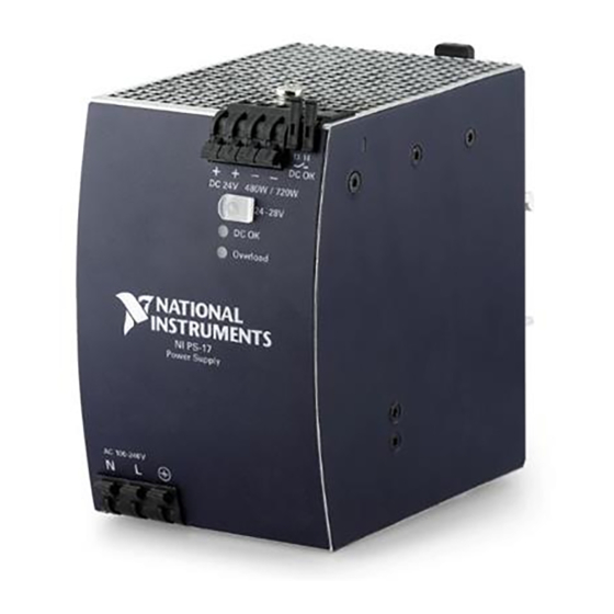
Figure 1-2. Front View of the NI PS-17 Power Supply Output Terminals The NI PS-17 has a total of four output terminals, providing two positive (+) output terminals and two negative (-) output terminals. Both positive terminals are wired together internally, and both negative terminals are wired together internally, as shown in Figure 1-1. -
Page 12: Dc Ok Led
The output voltage may be adjusted above 28 V by the potentiometer, but voltages beyond 28 V are not guaranteed. Note Output voltages greater than 28 V are not supported on an NI PS-17 unit. DC OK LED This green LED indicates the status of available DC power through the output terminals. -
Page 13: Dc Ok Relay Contact
This is an important condition to consider if the load is a battery, the power supply is used in parallel, or the power supply is used for N + 1 redundant systems. © National Instruments NI PS-17 Power Supply User Manual... -
Page 14: Restrictions For Using The Dc Ok Contact In Input Terminals
PANEL MOUNTING KIT FOR NI PS-15/16/17 Side Mounting Kit The Side Mounting Kit (199431-01) allows you to mount the NI PS-17 on its side to a wall, panel surface, or a DIN-Rail for reduced installation depth. Refer to the NI PS-15/16/17 Side Mount Brackets Installation Guide for more information. -
Page 15: Installation And Configuration
Installation and Configuration This chapter describes how to prepare and operate the NI PS-17 power supply. Mounting Orientation and Installation This section describes the different mounting orientations, and the effect that mounting orientation has on power supply performance. Mounting orientations other than input terminals on the bottom and output on the top require a reduction in continuous output power or a limitation in the maximum allowed ambient temperature. - Page 16 60 °C Output Current 20 A Mounting Orientation D (Horizontal ccw) Ambient Temperature 60 °C Output Current 20 A Mounting Orientation E (Horizontal ccw) Ambient Temperature 60 °C Figure 2-1. NI PS-17 Mounting Orientations NI PS-17 Power Supply User Manual ni.com...
-
Page 17: Wiring The Terminals
Getting Started. Wiring The Terminals This section describes wiring for the NI PS-17 power supply. The wiring terminals on the power supply are bi-stable, quick-connect spring clamp terminals. When shipped, their default position is open. Table 2-1 provides a list of basic requirements for wiring. - Page 18 Ensure that all wires are properly seated and not loose. Ensure that the rest of your equipment is ready to be powered without creating a hazard. Apply MAINS voltage to the NI PS-17 power supply. NI PS-17 Power Supply User Manual ni.com...
-
Page 19: Operating The Ni Ps-17
Chapter 2 Installation and Configuration Operating the NI PS-17 This section provides general information on the operation of the NI PS-17 power supply. Serial Operation The NI PS-17 can operate in series to increase the output voltage. Figure 2-3 shows the NI PS-17 in a serial configuration. -
Page 20: Parallel Operation
The simplest way is to put two NI PS-17 power supplies in parallel. If one power supply unit fails, the other one is automatically able to support the load current without any interruption. -
Page 21: Daisy-Chaining Outputs
+ + – – + + – – – Load Load Power Power Power Power Supply Supply Supply Supply Distribution Input Input Input Input Terminals Figure 2-5. Daisy-Chaining and Distribution Terminals © National Instruments NI PS-17 Power Supply User Manual... -
Page 22: Two-Phase Power Operation
Protection section. External Input Protection The NI PS-17 power supply is tested and approved for branch circuits up to 20 A. External protection is only required if the supplying branch has an ampacity greater than 20 A. In some countries local regulations might apply, so check local codes and local requirements. -
Page 23: Operation In A Sealed Enclosure
The inside temperature defines the ambient temperature for the power supply. The following is the result of such an installation, where the NI PS-17 power supply was placed in the middle of a sealed enclosure, and no other... -
Page 24: Cooling
However, you must not cover the ventilation grid (for example, with cable conduits) by more than 30%. Proper installation clearance for the NI PS-17 is 40 mm on top, 20 mm on the bottom, 5 mm on the left and right side when loaded permanently with full power. -
Page 25: Peak Current Capability
Output voltage dips from 24 V to 17.5 V. Figure 2-8. Peak Current Capacity Output Voltage Dips Note The DC OK relay triggers when the voltage dips more than 10% for more than 1ms. © National Instruments 2-11 NI PS-17 Power Supply User Manual... -
Page 26: Charging Batteries
Chapter 2 Installation and Configuration Charging Batteries The NI PS-17 power supply can be used for float-charging of lead-acid or maintenance-free 24 V VRLA batteries. Caution Use only matched batteries when putting 12 V types in series. Complete the following instructions to charge batteries. -
Page 27: Output Circuit Breakers
Power Supply Load – – Figure 2-9. Breaker Trip Test 1 The following circuit breaker tripped during the test: ≤25 A A- or Z-Characteristic ≤20 A B-Characteristic ≤13 A C-Characteristic © National Instruments 2-13 NI PS-17 Power Supply User Manual... - Page 28 150 mΩ (test results). Table 2-3 shows that up to 20.9 m of wire with a cross section of 2.5 mm is below 150 mΩ. You should not use a wire smaller than 2.5 mm NI PS-17 Power Supply User Manual 2-14 ni.com...
-
Page 29: Inductive And Capacitive Loads
Chapter 2 Installation and Configuration Inductive and Capacitive Loads The NI PS-17 is designed to supply any kind of load, including unlimited capacitive and inductive loads. Repetitive Pulse Loading Typically, a load current is not constant; it varies over time. Figure 2-11 provides a basic overview of repetitive pulse loading. -
Page 30: Utilizing The Maximum Duty Cycle Curve
Make a vertical line at P = 150%. PEAK Make a horizontal line where the vertical line crosses the P = 50% curve. Read the Maximum Duty Cycle from the Duty Cycle-axis (= 0.37). NI PS-17 Power Supply User Manual 2-16 ni.com... - Page 31 Table 2-4. Examples of Pulse Load Compatibility PEAK PEAK 720 W >1.3 s 720 W 240 W 0.1 s >0.16 s 720 W 240 W >1.6 s 720 W 480 W >25 s © National Instruments 2-17 NI PS-17 Power Supply User Manual...
-
Page 32: Appendix A Specifications
Specifications This appendix contains specifications for the NI PS-17 power supply. Note Specifications are subject to change without notice. Must be mounted in an enclosure by qualified personnel. Refer to Hazardous Voltages Figure A-1 for more information. This power supply is designed for installation in an enclosure and is intended for general use, such as in industrial control, office, communication, and instrumentation equipment. - Page 33 Appendix A Specifications 1 Suitably rated NEMA or IP enclosure that requires tool access 2 NI PS-17 Power Supply Figure A-1. NI PS-17 Power Supply 43.7 35.5 + + – – DC 24V 480W/720W – DC OK Overload AC 100-240V 28.6...
-
Page 34: Ac Input
The crest factor is the mathematical ratio of the peak value to the RMS value of the input current waveform. Rated Input Full Range Power 500ms 200ms 60 V 85 V 276 V 300 Vac Figure A-3. Input Voltage Range © National Instruments NI PS-17 Power Supply User Manual... - Page 35 10 12 14 16 18 20 A Figure A-5. Input Current vs. Output Load Power Factor, typ. 0.95 0.85 Output Current 0.75 10 12 14 16 18 20 A Figure A-6. Power Factor vs. Output Load NI PS-17 Power Supply User Manual ni.com...
-
Page 36: Dc Input
Medium curve: Input voltage 500 V / DIV Output Lower curve: Output voltage 20 V / DIV Voltage Time scale: 100 ms / DIV Figure A-7. Input Inrush Current, Typical Behavior © National Instruments NI PS-17 Power Supply User Manual... -
Page 37: Hold-Up Time
– 5% Output Voltage Hold-up Time Figure A-9. Shutdown Behavior, Definitions At no load, the hold-up time can be up to several seconds. The green DC OK LED Note is lit during this time. NI PS-17 Power Supply User Manual ni.com... -
Page 38: Output
Output Voltage 28 V Short term <5s then auto switching to curve + Continuously available Output Below 20Vdc hiccup mode Current 40 A Figure A-10. Output Voltage vs. Output Current, Typical © National Instruments NI PS-17 Power Supply User Manual... -
Page 39: Bonuspower
Load impedance 50 mΩ, up to 4 s, refer to Figure A-10 Bonus time Typical At 24 V, 30 A, duration until the voltage dips, refer to Figure A-11 Minimum 3.5 s Maximum 4.5 s NI PS-17 Power Supply User Manual ni.com... -
Page 40: Peak Current Capability
At 40 A for 20 ms, resistive load Typical From 24 V to 18 V At 80 A for 2 ms, resistive load Typical From 24 V to 17.5 V At 80 A for 5 ms, resistive load © National Instruments NI PS-17 Power Supply User Manual... -
Page 41: Efficiency And Power Losses
Efficiency vs. input voltage, 24V, 20A Losses vs. input voltage, 24V, 20A Efficiency Power Losses 50 W Input Voltage Input Voltage 260 Vac 260 Vac Figure A-13. NI PS-17 Efficiency and Losses NI PS-17 Power Supply User Manual A-10 ni.com... -
Page 42: Reliability
Reliability The lifetime expectancy shown in Table A-1 indicates the service life of the NI PS-17, and is determined by the lifetime expectancy of the built-in electrolytic capacitors. Lifetime expectancy is specified in operational hours. Lifetime expectancy is calculated according to the capacitor’s manufacturer specification. -
Page 43: Used Substances
Input Output Earth, PE – Figure A-14. Dielectric Strength Table A-2 lists the tests that have been run to determine the NI PS-17 dielectric strength, and the results of each test. Table A-2. Dielectric Strength Test Results Test Duration Type test... -
Page 44: Environment
Above 2000 m (6500 ft), refer to Figure A-16 Over-voltage category EN 50178, altitudes up to 2000 m Altitudes from 2000 m to 6000 m Degree of pollution EN 50178, not conductive © National Instruments A-13 NI PS-17 Power Supply User Manual... -
Page 45: Protection Features
2000 4000 6000 m Figure A-16. Output Current vs. Altitude Note The ambient temperature is defined as the temperature 2cm below the NI PS-17. Protection Features Output protection Electronically protected against overload, no-load and short-circuits Output over-voltage Typical 32 V... -
Page 46: Safety Guidelines For Hazardous Locations
Safety Guidelines for Hazardous Locations The NI PS-17 is suitable for use in Class I, Division 2, Groups A, B, C, D, T4 hazardous locations; Class I, Zone 2, AEx nA IIC T4, and Ex nA IIC T4 hazardous locations; and nonhazardous locations only. - Page 47 II 3G and is suitable for use in Zone 2 hazardous locations, in ambient temperatures of -40 °C ≤ Ta ≤ 70 °C. If you are using the NI PS-17 in Gas Group IIC hazardous locations, you must use the device in an NI chassis that has been evaluated as Ex nC IIC T4, EEx nC IIC T4, Ex nA IIC T4, or Ex nL IIC T4 equipment.
-
Page 48: Switching Frequencies
Resonant converter, input voltage and load dependent Notes For the standards applied to assess the EMC of this product, refer to the Online Product Certification section. For EMC compliance, operate this device with shielded cabling. © National Instruments A-17 NI PS-17 Power Supply User Manual... - Page 49 For additional environmental information, refer to the Minimize Our Environmental Impact web page at . This page ni.com/environment contains the environmental regulations and directives with which NI complies, as well as other environmental information not included in this document. NI PS-17 Power Supply User Manual A-18 ni.com...
- Page 50 Instruments WEEE initiatives, and compliance with WEEE Directive 2002/96/EC on Waste and Electronic Equipment, visit ni.com/environment/weee National Instruments (RoHS) National Instruments RoHS ni.com/environment/rohs_china (For information about China RoHS compliance, go to ni.com/environment/rohs_china © National Instruments A-19 NI PS-17 Power Supply User Manual...
-
Page 51: Technical Support And Professional Services
You can also register for instructor-led, hands-on courses at locations around the world. • System Integration—If you have time constraints, limited in-house technical resources, or other project challenges, National Instruments © National Instruments NI PS-17 Power Supply User Manual... - Page 52 You also can visit the Worldwide Offices section of ni.com/niglobal to access the branch office Web sites, which provide up-to-date contact information, support phone numbers, email addresses, and current events. NI PS-17 Power Supply User Manual ni.com...
-
Page 53: Index
NI PS-17, 1-1 dielectric strength specifications, A-11 wiring the NI PS-17, 2-3 dimension specifications, A-1 instrument drivers (NI resources), B-1 documentation NI resources, B-1 related documentation, ix drivers (NI resources), B-1 © National Instruments NI PS-17 Power Supply User Manual... - Page 54 1-6 PS-17 operation, 2-5 orientation, 2-1 parallel, 2-6 orientation (figure), 2-2 increase power, 2-6 redundancy, 2-6 serial, 2-5 figure, 2-5 recycling hardware, A-19 two-phase, 2-8 related documentation, ix peak current capability, 2-11 NI PS-17 Power Supply User Manual ni.com...
- Page 55 2-9 figure, 2-8 serial operation, 2-5 service parts, 2-10 side mounting kit, 1-6 software (NI resources), B-1 unpacking the NI PS-17 power supply, 1-1 specifications use for charging batteries, 2-12 AC input, A-3 used substances specifications, A-12 CE compliance, A-18...
Need help?
Do you have a question about the PS-17 and is the answer not in the manual?
Questions and answers