
Related Manuals for National Instruments NI PS-14


Summary of Contents for National Instruments NI PS-14
- Page 1 Power Supply NI PS-14 Power Supply User Manual NI PS-14 Power Supply User Manual October 2023 374228B-01...
- Page 2 11500 North Mopac Expressway Austin, Texas 78759-3504 USA Tel: 512 683 0100 For further support information, refer to the NI Services appendix. To comment on NI documentation, refer to the NI website at and enter the Info Code ni.com/info feedback © 2013–2023 National Instruments Corporation. All rights reserved.
- Page 3 National Instruments Corporation. National Instruments respects the intellectual property of others, and we ask our users to do the same. NI software is protected by copyright and other intellectual property laws. Where NI software may be used to reproduce software or other materials belonging to others, you may use NI software only to reproduce materials that you may reproduce in accordance with the terms of any applicable license or other legal restriction.
- Page 4 ™ The ExpressCard word mark and logos are owned by PCMCIA and any use of such marks by National Instruments is under license. The mark LabWindows is used under a license from Microsoft Corporation. Windows is a registered trademark of Microsoft Corporation in the United States and other countries.
- Page 5 Operation of this hardware in a residential area is likely to cause harmful interference. Users are required to correct the interference at their own expense or cease operation of the hardware. Changes or modifications not expressly approved by National Instruments could void the user’s right to operate the hardware under the local regulatory rules.
-
Page 7: Table Of Contents
Panel Mounting Kit ....................1-4 Chapter 2 Installation and Configuration Mounting Orientation and Installation ................2-1 Wiring The Terminals ...................... 2-3 Operating the NI PS-14 ....................2-4 Serial Operation ......................2-4 Parallel Operation ..................... 2-4 Two-Phase Power Operation ..................2-5 External Input Protection..................2-5 Operation in a Sealed Enclosure................ - Page 8 Contents Input Current Inrush Surge ....................A-5 Hold-up Time........................A-6 Output ..........................A-7 Peak Current Capability.................... A-8 Efficiency and Power Losses .................... A-8 Reliability.......................... A-9 Dielectric Strength ......................A-10 Used Substances ....................... A-11 Environment........................A-12 Protection Features ......................A-13 Appendix B NI Services Index viii | ni.com...
-
Page 9: About This Manual
NI PS-14 Power Supply User Manual describes the features and specifications of the NI PS-14 power supply and contains information about installing the power supply. Related Documentation The following documents contain information you might find helpful as you read this manual: •... -
Page 11: Getting Started
Getting Started This chapter describes the key features of the NI PS-14 power supply and lists the kit contents and mounting equipment you can order from NI. Unpacking Carefully inspect the shipping container and the power supply for damage. Check for visible damage to the metal work. -
Page 12: Power Supply Description
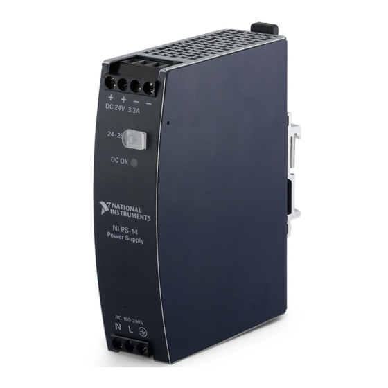
For more information, refer to Appendix A, Specifications. Power Supply Description Figures 1-1 and 1-2 show the functional description and front panel features of the NI PS-14. Figure 1-1 shows the functional diagram for the NI PS-14. Figure 1-1. NI PS-14 Functional Diagram... -
Page 13: Output Terminals
The output voltage potentiometer, shown in Figure 1-2, sets the output voltage from the NI PS-14. The factory setting output voltage is 24.1 V ±0.2% (at full load when the power supply is cold), and the potentiometer allows adjusting the output voltage from 24-28 V on any unit. -
Page 14: Dc On Led
PANEL MOUNTING KIT FOR NI PS-14/15/16/17 Side Mounting Kit The Side Mounting Kit (199429-01) allows you to mount the NI PS-14 on its side to a wall, panel surface, or a DIN-Rail for reduced installation depth. Refer to the NI PS-14/15/16/17/25/26 Side Mount Brackets Installation Guide at for more information. -
Page 15: Installation And Configuration
Installation and Configuration This chapter describes how to prepare and operate the NI PS-14 power supply. Mounting Orientation and Installation This section describes the different mounting orientations and the effect that mounting orientation has on power supply performance. Mounting orientations other than input terminals on the bottom and output on the top require a reduction in continuous output power or a limitation in the maximum allowed ambient temperature. - Page 16 Output Current Mounting Orientation E (Horizontal ccw) Ambient Temperature 60°C Mount the NI PS-14 according to the installation instructions included with your mounting kit. For details on the mounting options available, refer to the Mounting Equipment section of Chapter 1, Getting Started.
-
Page 17: Wiring The Terminals
NI PS-14 Power Supply User Manual Wiring The Terminals This section describes wiring for the NI PS-14. Table 2-1 provides a list of basic requirements for wiring. Table 2-1. Wiring Requirements Type Screw Terminals Solid wire 0.5 to 6 mm Stranded wire 0.5 to 4 mm... -
Page 18: Operating The Ni Ps-14
This section provides general information on operating the NI PS-14. Serial Operation The NI PS-14 can operate in series to increase the output voltage. Figure 2-2 shows the NI PS-14 in a serial configuration. Figure 2-2. NI PS-14 in Serial Operation Unit A –... -
Page 19: Two-Phase Power Operation
External Input Protection The NI PS-14 is tested and approved for branch circuits up to 20 A. External protection is required only if the supplying branch has an ampacity greater than 20 A. In some countries local regulations might apply, so check local codes and local requirements. -
Page 20: Operation In A Sealed Enclosure
(for example, with cable conduits) by more than 30%. Proper installation clearance for the NI PS-14 is 40 mm on top, 20 mm on the bottom, and 5 mm on the left and right side when loaded permanently with full power. If the adjacent device is a heat source, 15 mm clearance is recommended between the NI PS-14 and the adjacent device. -
Page 21: Service Parts
Service Parts The NI PS-14 does not contain any serviceable parts. If an internal fuse trips, it is caused by an internal defect. If damage or malfunction occurs during operation, immediately turn the power off and send the NI PS-14 to NI for inspection. -
Page 22: Charging Batteries
(Electro Magnetic Force). The NI PS-14 is resistant to this and does not malfunction when a load feeds back voltage to the power supply, regardless of whether the power supply itself is on or off. - Page 23 NI PS-14 Power Supply User Manual Test 1: Short circuit with S1 on the power supply end of the cable (loop impedance approximately 20 mΩ). The input voltage was 230 V and the load current was 0 A. Figure 2-5. Breaker Trip Test 1...
-
Page 24: Inductive And Capacitive Loads
(test results). Table 2-3 shows that up to 32.6 m of wire with a cross section of 1.5 mm is below 390 mΩ. You should not use a wire smaller than 1.5 mm Inductive and Capacitive Loads The NI PS-14 is designed to supply any kind of load, including unlimited capacitive and inductive loads. 2-10 | ni.com... -
Page 25: Appendix A Specifications
Specifications This appendix includes specifications for the NI PS-14 power supply. Specifications are subject to change without notice. Note Must be mounted in an enclosure by qualified personnel. Refer to Caution Figure A-1 for more information. This power supply is designed for installation in an enclosure and is intended for general use, such as in industrial control, office, communication, and instrumentation equipment. -
Page 26: Ac Input
Appendix A Specifications Figure A-2. NI PS-14 Dimensions 25.4 + + – – DC 24 V 3.3 A 24– 28 V DC on AC 100--240 V Depth: 102 mm (4.02 in.) 19.1 DIN-Rail Depth Width: 32 mm (1.26 in.) AC Input... - Page 27 NI PS-14 Power Supply User Manual Typical/ Maximum 100 V 120 V 230 V Input current Typical 1.5 A 1.24 A 0.68 A At 24 V, 3.3 A, refer to Figure A-5 Power Typical 0.62 0.61 0.56 At 24 V, 3.3 A, refer to...
-
Page 28: Dc Input
Appendix A Specifications Figure A-4. Turn On Behavior, Definitions Input Voltage – 5% Output Voltage Start-up Rise delay Time Figure A-5. Input Current Vs. Output Load Input 1.8 A Current, typ. (a) 100 Vac (b) 120 Vac (c) 230 Vac Output Current 3.0 3.5 A Figure A-6. -
Page 29: Input Current Inrush Surge
NI PS-14 Power Supply User Manual Output current Maximum 2.5 A At 24 V and an input voltage between 88 to 110 V refer to Figure A-7 Maximum 3.3 A At 24 V and an input voltage between 110 to 375 V... -
Page 30: Hold-Up Time
Appendix A Specifications Figure A-8. Input Inrush Current, Typical Behavior Input Current Start-up delay = Inrush delay Input: 230 Vac Input Voltage Output: 24 V, 3.3 A Ambient: 25 °C Input Voltage Upper curve: Input current 20 A / DIV Output Voltage Medium curve: Input voltage 500 V / DIV... -
Page 31: Output
NI PS-14 Power Supply User Manual Figure A-10. Shutdown Behavior, Definitions Zero Transition Intput Voltage Output – 5% Voltage Hold-up Time At no load, the hold-up time can be up to several seconds. The green DC OK Note LED is lit during this time. -
Page 32: Peak Current Capability
Appendix A Specifications Figure A-11. Output Voltage Vs. Output Current, Typical Adjustment Output Voltage Range 28 V a) 100 Vac b) 120 Vac c) 230 Vac Output Current Peak Current Capability The power supply can deliver a peak current which is higher than the specified short term current. -
Page 33: Reliability
Vac c Reliability The lifetime expectancy shown in Table A-1 indicates the service life of the NI PS-14 and is determined by the lifetime expectancy of the built-in electrolytic capacitors. Lifetime expectancy is specified in operational hours. Lifetime expectancy is calculated according to the capacitor’s manufacturer specification. -
Page 34: Dielectric Strength
Appendix A Specifications Table A-1. Reliability Specifications Minimum/ Maximum AC 100 V AC 120 V AC 230 V Lifetime Minimum 57,000 64,000 77,000 40 °C, 24 V, expectancy hours hours hours 3.3 A Minimum 160,000 > 15 years > 15 years 25 °C, 24 V, hours 3.3 A... -
Page 35: Used Substances
Figure A-13. Dielectric Strength Input Output – Earth, PE Table A-2 lists the tests that have been run to determine the NI PS-14 dielectric strength, and the results of each test. Table A-2. Dielectric Strength Test Results Test Duration Type test... -
Page 36: Environment
Appendix A Specifications Environment Operational temperature -25 °C to +70 °C Resistive load (-13 °F to 158 °F) Reduce output power according to Figure A-14 Output de-rating 1.8 W/°C 60 to 70 °C (140 °F to 158 °F) Storage temperature -40 to +85 °C Storage and transportation (-40 °F to 185 °F) -
Page 37: Protection Features
NI PS-14 Power Supply User Manual Figure A-14. Output Current Vs. Ambient Temperature Allowable Output Current at 24 V Ambient Temperature –25 60 70° C The ambient temperature is defined as the temperature 2 cm below the Note NI PS-14. - Page 38 Appendix A Specifications Penetration >3.5 mm From screws, small parts, and so on protection Over-temperature — protection Input transient Metal Oxide Varistor protection Internal input fuse T6.3A H.B.C. Not user replaceable In case of a protection event, audible noise may occur. Note Safety This product is designed to meet the requirements of the following standards of safety for...
- Page 39 NI PS-14 Power Supply User Manual Conducted EN 61000-4-6 0.15 to 80 MHz 10 V Criterion A disturbance Mains voltage dips EN 61000-4-11 0% of 100 V Criterion B 20 ms 40% of 100 V 40 V Criterion C 200 ms...
- Page 40 Appendix A Specifications Radiated emission EN 55011, EN 55022 Class B Harmonic input EN 61000-3-2 Fulfilled (Class A) current Voltage fluctuations, EN 61000-3-3 Fulfilled flicker This device complies with FCC Part 15 rules. Note Operation is subjected to following two conditions: (1) this device may not cause harmful interference, and (2) this device must accept any interference received, including interference that may cause undesired operation.
- Page 41 NI PS-14 Power Supply User Manual For the standards applied to assess the EMC of this product, refer to the Note Product Certifications and Declarations section. For EMC compliance, operate this device with shielded cabling. Certifications LISTED LISTED as Industrial Control Equipment (UL 508) IND.
- Page 42 Appendix A Specifications A-18 | ni.com...
-
Page 43: Ni Services
• System Integration—If you have time constraints, limited in-house technical resources, or other project challenges, NI Alliance Partner members can help. To learn more, call your local NI office or visit ni.com/alliance © National Instruments Corporation | B-1... - Page 44 Appendix B NI Services • Training and Certification—The NI training and certification program is the most effective way to increase application development proficiency and productivity. Visit for more information. ni.com/training – The Skills Guide assists you in identifying the proficiency requirements of your current application and gives you options for obtaining those skills consistent with your time and budget constraints and personal learning preferences.
-
Page 45: Index
Index mounting the NI PS-14, 2-1 unpacking the NI PS-14, 1-1 AC input specifications, A-2 wiring the NI PS-14, 2-3 back feeding loads, 2-8 kit contents, 1-1 capacitive loads, 2-10 loads certification specifications, A-17 back feeding, 2-8 charging batteries, use, 2-8... - Page 46 2-7 figure, 2-5 figure, 2-8 specifications, A-8 power loss specifications, A-8 unpacking the NI PS-14 power supply, 1-1 protection features specifications, A-13 use for charging batteries, 2-8 used substances specifications, A-11 related documentation, ix reliability specifications, A-9...
Need help?
Do you have a question about the NI PS-14 and is the answer not in the manual?
Questions and answers