Planet IPX-300 Series User Manual
Internet telephony pbx system
Hide thumbs
Also See for IPX-300 Series:
- Quick installation manual (20 pages) ,
- User manual (96 pages)
Table of Contents
Advertisement
Quick Links
Download this manual
See also:
User Manual
Advertisement
Table of Contents

Related Manuals for Planet IPX-300 Series


Summary of Contents for Planet IPX-300 Series
- Page 1 Internet Telephony PBX System IPX-300 Series User’s manual Version 1.0.1...
- Page 2 Copyright Copyright (C) 2008 PLANET Technology Corp. All rights reserved. The products and programs described in this User’s Manual are licensed products of PLANET Technology, This User’s Manual contains proprietary information protected by copyright, and this User’s Manual and all accompanying hardware, software, and documentation are copyrighted.
- Page 3 Revision User’s Manual for PLANET Internet Telephony PBX System: Model: IPX-300/IPX-300W Rev: 1.01 (Feburary, 2008) Part No. EM-IPX300 Series V1.01...
-
Page 4: Table Of Contents
TABLE OF CONTENTS Chapter 1 ....................6 Introduction.................... 6 Overview..........................6 Package Content .......................8 Physical Details .........................8 Front Panel Indicators....................8 Rear Panel Indicators....................9 Chapter 2 Preparations & Installation ..........10 Physical Installation Requirement ................10 Network Interface quick configurations ..............11 Chapter 3 IP PBX Setup ..............16 SIP Basic Setting ......................16 User Extensions Setup....................18 Trunk Management –... - Page 5 IP Phone and Wi-Fi Phone register to IPX-300W ............70 IP Phone and Wi-Fi Phone make off-Net calls via Gateway........74 IP Phone and Wi-Fi Phone make external SIP Proxy calls via SIP Trunk....79 Appendix E ................... 81 IPX-300 Series Specifications ..................81...
-
Page 6: Chapter 1
Chapter 1 Introduction Overview PLANET IPX-300/IPX-300W IP PBX telephony systems (“IP PBX” in the following term) are designed and optimized for the small business in daily communications. It can support up to 100 user registrations and easy to install and manage a fully working system with the convenience and cost advantages. - Page 7 - Display 100 Registered User’s Status: Unregistered / Registered / On-Call • Call Features - Call Forward Immediate - Call Forward on Busy - Call Forward on No Answer - Call Pickup / Call Park - Caller ID - Music on Hold / Music on Transfer - Call Transfer / Call Hold / Call Waiting - Three-way conference with feature phones (VIP-154T series, VIP-155PT/ 350PT/ 550PT and VIP-156/ 157/ 158/ 161W series)
-
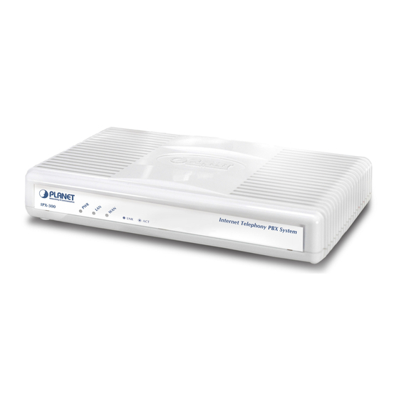
Page 8: Package Content
Package Content The contents of your product should contain the following items: Internet Telephony PBX system unit Power Adapter Quick Installation Guide User’s Manual CD Physical Details The following figure illustrates the front/rear panel of IP PBX. Front Panel Indicators Figure 1-1. -
Page 9: Rear Panel Indicators
Rear Panel Indicators Figure 1-3. Rear Panel of IPX-300 Figure 1-4. Rear Panel of IPX-300W 12V DC 12V DC Power input outlet The reset button, when pressed, resets the IP PBX without the Reset need to unplug the power cord. port supports auto... -
Page 10: Chapter 2 Preparations & Installation
Chapter 2 Preparations & Installation Physical Installation Requirement This chapter illustrates basic installation of IP PBX • Network cables. Use standard 10/100BaseT network (UTP) cables with RJ45 connectors. • TCP/IP protocol must be installed on all PCs. For Internet Access, an Internet Access account with an ISP, and either of a DSL or Cable modem (for WAN port usage) Administration Interface PLANET IP PBX provides GUI (Web based, Graphical User Interface) for machine management and... -
Page 11: Network Interface Quick Configurations
In order to connect machine for administration, please Note locate your PC in the same network segment (192.168.0.x) of IP PBX. If you’re not familiar with TCP/IP, please refer to related chapter on user’s manual CD or consult your network administrator for proper network configurations. Network Interface quick configurations Wizard for Quick Setup of the IP PBX, after finishing the authentication, please click “Wizard”... - Page 12 The IP PBX must access remote AP .Please be sure that have account to access from remote AP. In this WISP & AP mode the network interface will change from WAN port to LAN port and all of network access will through by remote AP. Step2.
- Page 13 Figure 2-4. Wizard-AP settings Step3. NAT Setting LAN IP Setting Private IP address for connecting to a local private network. LAN IP Address (Default: 192.168.0.1) Subnet mask for the local private network (Default: Subnet Mask 255.255.255.0) DHCP Server Enable to open LAN port DHCP server Assigned DHCP IP Address DHCP server range from start IP to end IP Client to ask DHCP server refresh time, range from 60 to...
-
Page 14: Service Provider
Step4. IPPBX Setup The IP PBX allows multiple ITSP providers / User Extensions registration by simply fill-in the required information in the provided table. Figure 2-6. Wizard-IP PBX settings Service Provider: Caller ID Service provider name Username Input Provider name Input Provider password Password Host... - Page 15 Figure 2-7. Wizard-Rebooting Please consult your ISP personnel to obtain proper PPPoE/IP address related information, and input carefully. Note If Internet connection cannot be established, please check the physical connection or contact the ISP service staff for support information.
-
Page 16: Chapter 3 Ip Pbx Setup
Chapter 3 IP PBX Setup SIP Basic Setting SIP (Session Initiation Protocol) is a request-response protocol, dealing with requests from clients and responses from servers. Participants are identified by SIP URLs. Requests can be sent through any transport protocol. SIP determines the end system to be used for the session, the communication media and media parameters, and the called party's desire to engage in the communication. - Page 17 Maximum duration of incoming registration/subscriptions we allow. Max Registration Time Default 3600 seconds. Minimum duration of registrations/subscriptions. Default 60 Min Registration Time seconds Default Incoming/Outgoing Default duration (in seconds) of incoming / outgoing registration. Registration Time Min RoundtripTime Minimum roundtrip time for messages to monitored hosts, Defaults to 200 ms (T1 Time) Language...
-
Page 18: User Extensions Setup
Register TimeOut Retry registration calls at every 'x' seconds (default 20). Number of registration attempts before we give up; 0 = Register Attempts continue forever. Table 3-2. Outbound DIP registration description NAT Support The externip, externhost and localnet settings are used if you use IP PBX behind a NAT device to communicate with services on the outside. - Page 19 Figure 3-5. User extension settings Advance Click to edit an extension other setting. Delete Click to delete an extension. Table 3-4. User extension description Advance Setup Figure 3-6. Extension advance settings User Extension Input Extension number Password Input Extension password Caller Id Input Extension caller id Table 3-5.
-
Page 20: Trunk Management - Sip Trunk
Call group / Pickup group select : Call Group An Extension can set single/multiple call group(s) 1-10 id Pickup Group An Extension can set single/multiple Pickup group(s) 1-10 id Table 3-6. Call / Pickup group description Call forward option : Call forward always Input forward always number Call forward on busy... - Page 21 Figure 3-8. Add new service providers Step 2. Fill in the required information in Service Provider Advance Setup page. Figure 3-9. Service provider advance setup The caller ID will be sent between the callee and caller and will Caller id be displayed on SIP device LCD panel for identification.
-
Page 22: Trunk Management - Gateway Trunk
will hear On / Off duty voice, default settings is “Enable”. select (For how to record On/Off duty voice please refer “Record Voice Menu”). Choose a pre-set hunt groups, default is “blank”. There are 3 types of combination setup. 1. If On duty/ Off duty voice is “Enabled”, after caller hear the voice menu one time, the call will be transferred to the pre-defined group for call attendant. - Page 23 for outgoing route. Figure 3-11. Trunk Group setting Add New Trunk Group Step 1. Press “Add” button to add an new Group Name information. Figure 3-12. Add an new Group Name Step 2. Fill in the required information in Trunk Group Setup page. Figure 3-13.
-
Page 24: Trunk Management - Dialing Rules
Figure 3-14. Trunk Group sample setting One-Stage Call: 1. If user dials 81123456, this call will hunt SIP_Trunk_1 and send 123456 to call out. 2. If user dials 82234567, this call will hunt SIP_Trunk_2 and send 234567 to call out. 3. - Page 25 Delete Length is the number of digits that will be stripped from Delete Length beginning of the dialed number. Prefix NO is the digits that will be added to the beginning of the Prefix NO dialed number. Table 3-12. Dialing Rules description Scenario Sample IP PBX has created one SIP Trunk and three Dialing Rules records for making outgoing trunk calls.
-
Page 26: Attendant Extension
to call out. 2. If user dials and hear the dial tone, then dial 022. This call will hunt SIP_Trunk_1 and send 882 to call out. 3. If user dials and hear the dial tone, then dial 033. This call will hunt SIP_Trunk_1 and send 993 to call out. -
Page 27: Time Rules
Figure 3-19. Auto-attendant sample Time Rules Defined Service providers based on date and time voice rule. Figure 3-20. Attendant time settings Day setting Defined Start day / end time Defined Start time / End time Time setting Month setting Defined Start Month / End Month Date setting Defined Start Date / End Date Table 3-13. -
Page 28: Record Voice Menu
Record Voice Menu Allow you to record On / Off duty voice menu over a register ip-phone. Figure 3-21. Record voice menu settings Pick up your register IP-Phone handset and press “function key + password “ to enter into voice menu guide. -
Page 29: Gereral Setting
Figure 3-22. Call parking settings Set an extension number to dial when need to park the Extension to Dial for Parking Calls call. Default number is 700. Set the Extension range for call parking retrieving. What extension to park calls on (Example: '701-720'). -
Page 30: Voice Mail
Enable: Dial the “ *1 + number ” enable call forward always function Call forward always Disable: Dial the “ * 2” disable call forward always function Enable: Dial the “ *3 + number ” enable call forward busy function Call forward Busy Disable: Dial the “... -
Page 31: Hunt Group Setting
Figure 3-26. Voice mail settings Max time of a voice mail Set a voice mail max time Max number of voice mail per folder Max number of messages per folder Dial voice mail number Dial “ *12 “ into voice mail guide Dial my voice mail number Dial “... - Page 32 Figure 3-28. Hunt Group settings Press “Add” to add a new Hunt Group; Press “Edit” to the edit a specified hunt group; Press “Delete” to delete a specified hunt group; Add New Hunt Group Step 1. Press “Add” button to add an new Group Name information. Figure 3-29.
- Page 33 Associate a dial number with a call group voice instruction to instruct incoming calls (e.g. If “20” is associated with Group Incoming Call Dial Number A, when the caller dial “20”, all extensions under Group A will ring). Default incoming call dial number is empty. Setup a timeframe to control the call group hunting timeout.
- Page 34 Figure 3-34. Delete Extension/User...
-
Page 35: Chapter 4 Network Setup
Chapter 4 Network Setup WAN & LAN Setup WAN (Wide Area Network) is a network connection connecting one or more LANs together over some distance. For example, the means of connecting two office buildings separated by several kilometers would be referred to as a WAN connection. The size of a WAN and the number of distinct LANs connected to a WAN is not limited by any definition. - Page 36 Static IP If you are a leased line user with a fixed IP address, enter in the IP address, subnet mask, gateway address, and DNS (domain name server) address(es) provided to you by your ISP. Each IP address entered in the fields must be in the appropriate IP form, which are four IP octets separated by a dot (x.x.x.x).
- Page 37 Figure 4-3. WAN-DHCP settings PPPoE Point-to-Point Protocol over Ethernet (PPPoE). Some ISPs provide DSL-based services and use PPPoE to establish communication link with end-users. If you are connected to the Internet through a DSL line, check with your ISP to see if they use PPPoE. If they do, you need to make sure the following items, PPPoE User name: Enter username provided by your ISP.
- Page 38 called www.IP-PBX.com. When we need to find the host name from an IP address we send a request to the host using its IP address. The host will respond with its host name. WAN Port MAC The MAC (Media Access Control) Address field is required by some Internet Service Providers (ISP). The default MAC address is set to the MAC address of the WAN interface in the device.
- Page 39 Figure 4-6. MTU and MRU settings For Static IP, both MTU and MRU are set to 1500 bytes as default value. Note For DHCP, both MTU and MRU are set to 1500 bytes as default value. For PPPoE, both MTU and MRU are set to 1492 bytes as default value. DNS Server DNS stands for Domain Name System.
-
Page 40: Dhcp
LAN Setting These are the IP settings of the LAN (Local Area Network) interface for the device. These settings may be referred to as "private settings". You may change the LAN IP address if needed. The LAN IP address is private to your internal network and cannot be seen on the Internet. The default IP address is 192.168.0.1 with a subnet mask of 255.255.255.0. - Page 41 Expired Time of the DHCP lease for each client computer. DHCP Server is a useful tool that automates the assignment of IP addresses to numbers of computers in your network. The server maintains a pool of IP addresses that you use to create scopes. (A DHCP scope is a collection of IP addresses and TCP/IP configuration parameters that are available for DHCP clients to lease.) Then, the server automatically allocates these IP addresses and related TCP/IP configuration settings to DHCP-enabled clients in the network.
-
Page 42: Wlan Setting (For Ipx-300W)
WLAN Setting (For IPX-300W) A WLAN is a data communication system that reduces the need for a wired connection, thereby adding new flexibility and convenience to your network. Using electromagnetic waves, WLAN's transmits and receives data over the air, minimizing the need for wired connections and combines data connectivity with user mobility. - Page 43 Select OPEN, WPA, WPA-PSK, WPA2, WPA2-PSK, WPA/WPA2 Authentication mix mode, WPA-PSK/WPA2-PSK mix mode .Default is OPEN Method mode. Table 4-5. AP mode description Example: Figure 4-13. AP mode application AP-Client Mode In this mode the IP PBX is used to access the Wireless Service Provider network by connecting wirelessly to the remote (Outdoor AP).
- Page 44 Note When IP PBX operate in AP-Client Mode, the WAN and LAN RJ-45 interface will be configured as a 2 port switch for connecting with 2 PCs for access wireless network For wireless connected type 802.11 B/G mixed/ 802.11b only / WLAN Mode 802.11G only Define the same as your Wireless Router uses.
- Page 45 Figure 4-15. AP-Client mode settings Figure 4-16. Search remote AP list page Note After scan and select the Outdoor AP, the channel and encryption method should be set the identical with the remote...
- Page 46 Example: Figure 4-17. Ap-Client mode application WISP & AP Mode The IP PBX can operate in AP-Client and access to another (Outdoor) AP. The wireless client needs to have the same SSID, Channel, Encryption settings as the main AP. The user may need to change the default IP to avoid IP conflicts.
- Page 47 When IP PBX operates in AP-Client (or WISP & AP) Mode, the Note WAN and LAN RJ-45 interface will be configured as a 2 port switch for connecting with 2 PCs for access wireless network. For wireless connected type 802.11 B/G mixed/ 802.11b only / WLAN Mode 802.11G only Define the same as your Wireless Router uses...
- Page 48 Figure 4-19. WISP & AP mode settings Scan usable network:Select list to remote AP SSID (magnifying glass) Figure 4-20. Search remote AP list page Note After scan and select the Outdoor AP, the channel and encryption method should be identical with the remote AP...
-
Page 49: Access Policy (For Ap And Wisp&Ap Mode)
Example: Figure 4-21. WISP & AP mode application Access Policy (For AP and WISP&AP mode) In IP PBX security, an access control list is a list of “allow Access Policy all / Reject all" to an MAC. MAX MAC List:64 Access Control List Table 4-8. -
Page 50: Static Route
Figure 4-23. Access policy settings Static Route Static routes are special routes that the network administrator manually enters into the router configuration for local network management. You could build an entire network based on static routes. The problem with doing this is that when a network failure occurs, the static route will not change without you performing the change. -
Page 51: Nat
NAT (Network Address Translation) serves three purposes: Provides security by hiding internal IP addresses. Acts like firewall. Enables a company to access internal IP addresses. Internal IP addresses that are only available within the company will not conflict with public IP. Allows a company to combine multiple ISDN connections into a single internet connection. - Page 52 Network Address Enable/Disable NAT. Translation IPsec (Internet Protocol Security) is a framework for a set of protocols for IPSec Pass Through security at the network or packet processing layer of network communication. Enable/Disable this framework verification. PPTP (Point-to-Point Tunneling Protocol) is a protocol that allows PPTP Pass Through corporations to extend their own corporate network through private "tunnels"...
- Page 53 LAN network. Depending on the requested service (TCP/UDP port number), the device redirects the external service request to the appropriate server within the LAN network. You will only need to input the LAN IP address of the computer running the service and enable it. A Virtual Server is defined as a service port, and all requests to this port will be redirected to the computer specified by the server IP.
-
Page 54: Packet Filter
Figure 4-28. Port trigger settings Enable Enable/Disable the port trigger, default setting is Disable. This is the port used to trigger the application. It can be either a single Trigger Port port or a range of ports. Trigger Type This is the protocol used to trigger the special application. This is the port number on the WAN side that will be used to access Public Port the application. - Page 55 The WAN IP port packet filter function, control a network IP port, Enable/Disable default setting is Enable. Enable/Disable the Internet to WAN IP source port rules, default Enable setting is Disable. Source IP This is the filter WAN IP address. Example: 209.131.36.158 This is the port used for source IP service.
-
Page 56: Url Filter
Block Day setting, select a All / Mon-Sat./ Mon-Fri./Mon./ Tues./ Wed./Thu./Fri./Sat./Sun. Time Block Time setting, select time range is 00:00 to 23:59 Table 4-15. Packet filter-MAC description URL Filter URL filter allows you to block sites based on a black list and white list. Sites matching the black list but not matching the white list will be automatically blocked and closed. -
Page 57: Upnp
Figure 4-31. Security settings Intrusion Detection Enable / Disable , network / internet security protection. Drop Malicious Enable / Disable , Detect and drop malicious application Packet layer traffic. Table 4-17. Security description UPnP UPnP provides support for communication between control points and devices. The network media, the TCP/IP protocol suite and HTTP provide basic network connectivity and addressing needed. - Page 58 DDNS, the users should use the WAN IP to reach internal server. It is inconvenient for the users if this IP is dynamic. With DDNS supported, you apply a DNS name (e.g., www.IPPBX.com) for your server (e.g., Web server) from a DDNS server. The outside users can always access the web server using the www.IP-PBX.com regardless of the WAN IP.
-
Page 59: Sntp
website Table 4-19. DDNS description SNTP The simple network management protocol (SNMP) forms part of the internet protocol suite as defined by the Internet Engineering Task Force (IETF). SNMP is used by network management systems to monitor network-attached devices for conditions that warrant administrative attention. It consists of a set of standards for network management, including an Application Layer protocol, a dIP-PBXbase schema, and a set of dIP-PBX objects. -
Page 60: Chapter 5 Management
Chapter 5 Management Admin Account The administrator account can access the management interface through the web browser. Figure 5-1. Management settings Assign a name to represent the administrator account. Maximum 16 Administrator Name characters. Legal characters can be the upper letter “A” to “Z”, lower letter “a”... -
Page 61: Date & Time
The administrator name and password are case-sensitive Note and the “blank” character is an illegal character Only the administrator account has the ability to change account password. Date & Time Manual Time Setting Figure 5-2. Date/Time-Manual time settings Manual Time Setting Set up the time manually. -
Page 62: Ping Test
Protocol used to help match your system clock with an accurate NTP Time Server time source. For example atomic clock or a server. Choose your time zone, Default is (GMT+8:00) Beijing, Time Zone Singapore, Taipei. Enable / Disable. Default is Disabling, time during which clocks Daylight Saving are set one hour ahead of local standard time;... -
Page 63: Factory Default
Factory Default This function is used to restore all the parameters back to factory default setting. You can use the Save/Restore Setting to check the factory default configuration, after you click on the Set button. Figure 5-6. Factory default settings Admin Account You can upgrade the firmware of the device using this tool. -
Page 64: Chapter 6 Information
Chapter 6 Information System Information System Information page indicates the current setup-status of the device, it includes LAN, WAN, (Status and MAC Address), Host Name / System Date time / Machines Life time and system firmware information. The information and options on this page will vary according to your WAN setting (Static IP, DHCP, or PPPoE). -
Page 65: Pbx Extension Status
PBX Extension Status This page displays the information of Extension/Users Registration status. Figure 6-2. Extension Status SIP device is connected to IPPBX Register OK The connection from/to the other end of SIP device is Talk on the telephone established. Sip device is not connected to IPPBX Register Unknown Table 6-1. - Page 66 Recorded information include: Source Number, Destination Number, Start Time, Answer Time, End Time, Duration Time and Status. Figure 6-4. Call Detail Record Press to go to the Next page; Press to go to the Previous page Source No Caller’s ID Destination No ID of destination extension / user Start Time...
-
Page 67: Appendix A
Appendix A How to use Call Parking function The followings are the Call Park function settings, and all of VoIP devices (ATA, GW and IP Phone) were registered with Wi-Fi IP PBX. Extension to Dial for Parking Calls: 700 Extensions to park calls on :701-720 Figure A-1. -
Page 68: Appendix B
Appendix B How to use Call Pick-up function The followings are the Call Pickup function settings, and all of VoIP devices (ATA, GW and IP Phone) were registered with IP PBX. Pickup Extension: *8 Figure B-1. Call Pickup sample scenario Ext.300 call to Ext.100, and Ext.100 is ringing. -
Page 69: Appendix C
Appendix C Record Voice Guide Process IPX-300W provides Record Voice Menu by Phone function. Please register your VoIP devices to Wi-Fi IP PBX at first, and then check the Record voice code from “IP PBX Setup -> record Voice Menu” page. Figure C-1. -
Page 70: Appendix D
Appendix D Voice Communication Samples The chapter shows you the concept and command to help you configure your IP PBX System through sample configuration. And provide several ways to make calls to desired destination in IP PBX. In this section, we’ll lead you step by step to establish your first voice communication via web browsers operations. - Page 71 Figure D-2. WLAN Setting of IPX-300W STEP 2: Browse to “IP PBX Setup User Extensions Setup” configuration menu. Figure D-3. User extension setting of IP PBX STEP 3: Click the “Add” button to create extension account ext.100 and ext.101.
- Page 72 Figure D-4. Add extension setting of IP PBX STEP 4: Please log in VIP-154T and browser to “SIP setting Domain Service” configuration menu. Insert the account/password information then save and reboot machine. The sample configuration screen is shown below: Data match with Figure D-3. IP PBX’s extension settings The IP address of IP PBX...
- Page 73 The IP address of IP PBX Figure D-6. SIP settings of VIP-192 Then browse to “SIP Account Settings” configuration menu and fill in the account/password information. The sample configuration screen is shown below: Data match with Figure D-3. IP PBX’s extension settings Figure D-7.
-
Page 74: Ip Phone And Wi-Fi Phone Make Off-Net Calls Via Gateway
IP Phone and Wi-Fi Phone make off-Net calls via Gateway In the following samples, we’ll introduce VIP-154T and VIP-192 makes off-Net Calls (PSTN calls) via VIP-480FO applications. Figure D-9. Installation example with VIP-480FO Machine Configuration: STEP 1: Please refer to the first sample and let VIP-154T and VIP-192 register to IP PBX. STEP 2: Please log in IP PBX via web browser and browse to “IP PBX Setup User Extensions Setup”... - Page 75 STEP 3: Browse to “IP PBX Setup Attendant Extension” configuration menu. Assign an attendant number which inexistence extension in Extension List and the sample configuration screen is shown below: Figure D-11. Assign an attendant number Pressing the “Submit” button for activate the configuration. STEP 4: Browse to “IP PBX Setup Trunk Management...
- Page 76 Figure D-13. Add Trunk Group number for grabbing the FXO ports of VIP-480FO STEP 6: Please log in VIP-480FO via web browser and browse to “Advance Setup VoIP Setup VoIP Basic” configuration menu. Insert the account/password information and set up the hunting function. The sample configuration screen is shown below: Figure D-14.
- Page 77 STEP 7: Browse to “Dialing Plan” configuration menu. Add an Incoming Dial Plan (no.1x) for redirect the PSTN outgoing calls to FXO ports. Figure D-17. Add an incoming dial plan STEP 8: Browse to “Port Status” configuration menu. Fill in the auto attendant number 555 to all of ports. ( Where 555 is the auto-attendant number of IP PBX ) Figure D-18.
- Page 78 Test the Scenario: 1. VIP-154T pick up the telephone 2. Dial the number: will hear the dial tone, and dial the number: 12345678. This call will hunt the FXO port of VIP-480FO and shall be able connect to the User A. 3.
-
Page 79: Ip Phone And Wi-Fi Phone Make External Sip Proxy Calls Via Sip Trunk
IP Phone and Wi-Fi Phone make external SIP Proxy calls via SIP Trunk In the following samples, we’ll introduce VIP-154T and VIP-192 makes SIP Proxy calls via SIP Trunk applications. Figure D-20. Installation example with VIP-480FO Machine Configuration: STEP 1: Please refer to the first sample and let VIP-154T and VIP-192 register to IP PBX. - Page 80 STEP 3: Browse to “IP PBX Setup Trunk Management Trunk Group” configuration menu. Add a Trunk Group for making external SIP Proxy calls. Figure D-22. Add Trunk Group number STEP 4: After the SIP Trunk has registered to FWD SIP Proxy successfully, the Service Provider Status page will show the registration status: Figure D-23.
-
Page 81: Appendix E
Appendix E IPX-300 Series Specifications Product Internet Telephony PBX System Wi-Fi Internet Telephony PBX System Model IPX-300 IPX-300W Hardware IEEE 802.11 b/g WLAN Standards Wireless Frequency 2.4GHz ~ 2.4835 GHz Range 64/128 bit WEP data encryption, WPA, WPA-PSK, WPA2, WPA2-PSK, WPA /... - Page 82 Backup and Restore Configuration file Call/Pickup Group Displays 100 Registered User’s Status: Unregistered / Registered / On-Call Displays 20 Registered Trunk’s Status: Unregistered / Registered Fax Support using G.711 Pass-Through or T.38** Caller ID Call Group Call Hold Call Waiting Call Transfer Call Forward (Always, Busy, No Answer) Call features...
Need help?
Do you have a question about the IPX-300 Series and is the answer not in the manual?
Questions and answers