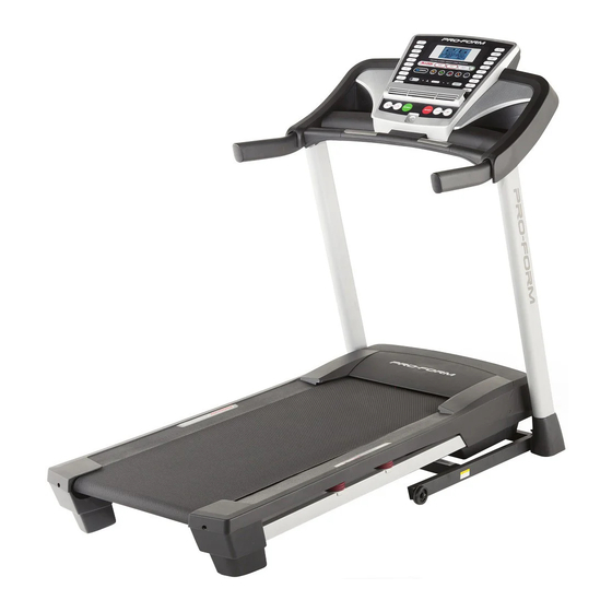
Pro-Form 730 Zlt Treadmill Manual
Uk manual
Hide thumbs
Also See for 730 Zlt Treadmill:
- Gebruikershandleiding (32 pages) ,
- Manuel de l'utilisateur (32 pages) ,
- Bedienungsanleitung (32 pages)
Table of Contents
Advertisement
Model No. PETL79713.0
Serial No.
USER’'S MANUAL
Write the serial number in the space
above for reference.
Serial Number
Decal
CUSTOMER SERVICE
UNITED KINGDOM
Call: 08457 089 009
From Ireland: 053 92 36102
Website: www.iconsupport.eu
E-mail: csuk@iconeurope.com
Write:
ICON Health & Fitness, Ltd.
c/o HI Group PLC
Express Way
CASTLEFORD
WF10 5QJ
UNITED KINGDOM
AUSTRALIA
Call: 1800 993 770
E-mail: australiacc@iconfitness.com
Write:
ICON Health & Fitness
PO Box 635
WINSTON HILLS NSW 2153
AUSTRALIA
CAUTION
Read all precautions and instruc-
tions in this manual before using
this equipment. Keep this manual
for future reference.
www.iconeurope.com
Advertisement
Table of Contents

Related Manuals for Pro-Form 730 Zlt Treadmill


Summary of Contents for Pro-Form 730 Zlt Treadmill
- Page 1 Model No. PETL79713.0 Serial No. USER’’S MANUAL Write the serial number in the space above for reference. Serial Number Decal CUSTOMER SERVICE UNITED KINGDOM Call: 08457 089 009 From Ireland: 053 92 36102 Website: www.iconsupport.eu E-mail: csuk@iconeurope.com Write: ICON Health & Fitness, Ltd. c/o HI Group PLC Express Way CASTLEFORD...
-
Page 2: Table Of Contents
If a decal is missing or illegible, see the front cover of this manual and request a free replacement decal. Apply the decal in the location shown. Note: The decals may not be shown at actual size. PROFORM is a registered trademark of ICON IP, Inc. -
Page 3: Important Precautions
IMPORTANT PRECAUTIONS WARNING: To reduce the risk of burns, fire, electric shock, or injury to persons, read all important precautions and instructions in this manual and all warnings on your treadmill before using your treadmill. ICON assumes no responsibility for personal injury or property damage sus- tained by or through the use of this product. - Page 4 21. Do not attempt to move the treadmill until DANGER: Always unplug the power it is properly assembled. (See ASSEMBLY cord immediately after use, before clean- on page 7 and HOW TO FOLD AND MOVE ing the treadmill, and before performing the THE TREADMILL on page 21.) You must be maintenance and adjustment procedures able to safely lift 45 lbs.
-
Page 5: Before You Begin
® 730 ZLT manual. To help us assist you, note the product model treadmill. The 730 ZLT treadmill provides an impressive number and serial number before contacting us. The selection of features designed to make your workouts model number and the location of the serial number at home more effective and enjoyable. -
Page 6: Part Identification Chart
PART IDENTIFICATION CHART Use the drawings below to identify small parts used for assembly. The number in parentheses below each draw- ing is the key number of the part, from the PART LIST near the end of this manual. The number following the key number is the quantity used for assembly. -
Page 7: Assembly
ASSEMBLY •• Assembly requires two persons. •• Assembly requires the following tools: the included hex keys •• Place all parts in a cleared area and remove the packing materials. Do not dispose of the packing one adjustable wrench materials until you nish all assembly steps. one Phillips screwdriver ••... - Page 8 3. Identify the Left Upright (75). Have a second person hold the Left Upright near the Base (80). See the inset drawing. Tie the wire tie in the Wire Left Upright (75) securely around the end of the Upright Wire (70). Then, insert the Upright Wire into the lower end of the Left Upright as you pull the other end of the wire tie through the Left Wire...
-
Page 9: The Left Handrail, Remove And Discard It
5. Identify the Left and Right Base Covers (73, 74). Slide the Left and Right Base Covers onto the Left and Right Uprights (75, 76) as shown. 6. Identify the Left Handrail (71). If there is a wire in the Left Handrail, remove and discard it. Hold the Left Handrail (71) near the Left Upright (75). - Page 10 7. Attach the Right Handrail (72) to the Right Upright (76) with two 3/8" x 3 1/2" Screws (9) and two 3/8" Star Washers (5). Start both Screws, but do not tighten them yet. 8. Insert the Console Frame (87) into the Handrails (71, 72).
- Page 11 9. With the help of a second person, hold the con- sole assembly near the Left Handrail (71) and the Right Handrail (not shown). Console Assembly Connect the Upright Wire (70) to the console wire. See the inset drawing. The connectors should slide together easily and snap into place.
- Page 12 11. Attach the two Console Clamps (34) to the con- sole assembly with four #8 x 3/4" Screws (6). Console Assembly See step 4. Tighten all six 3/8" x 4" Screws (4). 12. Identify the Left and Right Trays (45, 85). Orient the Trays as shown and attach each Tray with four #8 x 3/4"...
- Page 13 13. Raise the Frame (49) to the position shown. Have a second person hold the Frame during the next two assembly steps. Attach the Latch Crossbar (96) to the Frame (49) with two 1/4" x 1 3/4" Screws (97). 14. Orient the Storage Latch (51) so that the large barrel and the latch knob are in the positions shown.
-
Page 14: Operation And Adjustment
OPERATION AND ADJUSTMENT HOW TO PLUG IN THE POWER CORD Follow the steps below to plug in the power cord. This product must be earthed. If it should malfunc- 1. Plug the indicated end of the power cord into the tion or break down, earthing provides a path of least socket on the treadmill. - Page 15 CONSOLE DIAGRAM FEATURES OF THE CONSOLE You can even listen to your favorite workout music or audio books with the sound system while you exercise. The treadmill console offers an impressive array of features designed to make your workouts more effec- To turn on the power, see page 16.
- Page 16 HOW TO TURN ON THE POWER HOW TO USE THE MANUAL MODE IMPORTANT: If the treadmill has been exposed to 1. Insert the key into the console. cold temperatures, allow it to warm to room tem- perature before turning on the power. If you do not See HOW TO TURN ON THE POWER at the left.
- Page 17 5. Follow your progress with the displays. When the manual mode is selected, the upper half of the display will Track show a track that represents Contacts 400 m (1/4 mile). As you walk or run, indicators will appear in succession around the track until the entire track appears.
- Page 18 HOW TO USE AN ONBOARD WORKOUT The workout will continue in this way until the last segment of the pro le ashes in the display and the 1. Insert the key into the console. last segment ends. The walking belt will then slow to a stop.
- Page 19 HOW TO USE AN 8-WEEK WEIGHT-LOSS 5. Start the workout. WORKOUT Press the Go button, and then press the Start but- 1. Insert the key into the console. ton to start the workout. See HOW TO TURN ON THE POWER on page 16. The workout will function in the same way as an onboard workout (see step 3 on page 18).
- Page 20 HOW TO USE THE SOUND SYSTEM THE INFORMATION MODE To play music or audio books through the console The console features an information mode that keeps sound system while you exercise, plug a 3.5 mm male track of treadmill usage information. The information to 3.5 mm male audio cable (not included) into the jack mode also allows you to select miles or kilometers as on the console and into a jack on your MP3 player,...
-
Page 21: How To Fold And Move The Treadmill
HOW TO FOLD AND MOVE THE TREADMILL HOW TO FOLD THE TREADMILL HOW TO MOVE THE TREADMILL To avoid damaging the treadmill, adjust the incline Before moving the treadmill, fold it as described at the to zero before you fold the treadmill. Then, remove left. -
Page 22: Troubleshooting
TROUBLESHOOTING Most treadmill problems can be solved by following SYMPTOM: The console displays remain lit when the simple steps below. Find the symptom that you remove the key from the console applies, and follow the steps listed. If further assis- tance is needed, see the front cover of this manual. - Page 23 Locate the Reed Switch (94) and the Magnet (95) SYMPTOM: The walking belt slows when walked on on the left side of the Pulley (43). Turn the Pulley until the Magnet is aligned with the Reed Switch. a. If the walking belt is overtightened, treadmill per- Make sure that the gap between the Magnet formance may decrease and the walking belt may and the Reed Switch is about 1/8 in.
- Page 24 SYMPTOM: The walking belt is off-center or slips b. If the walking belt slips when walked on, rst when walked on remove the key and UNPLUG THE POWER CORD. Using the hex key, turn both idler roller a. If the walking belt is off-center, rst remove the screws clockwise, 1/4 of a turn.
-
Page 25: Exercise Guidelines
EXERCISE GUIDELINES Burning Fat——To burn fat effectively, you must exer- WARNING: cise at a low intensity level for a sustained period of Before beginning this time. During the first few minutes of exercise, your or any exercise program, consult your physi- body uses carbohydrate calories for energy. -
Page 26: Part List
PART LIST Model No. PETL79713.0 R0513A Key No. Qty. Description Key No. Qty. Description #8 x 1/2" Ground Screw Storage Latch 3/8" x 2 1/2" Bolt Right Rear Foot 3/8" Nut Left Rear Foot 3/8" x 4" Screw #8 x 1/2" Pan Head Screw 3/8"... - Page 27 Key No. Qty. Description Key No. Qty. Description #8 x 3/4" Bolt Filter Bracket #8 Nut Grounding Bracket #8 Star Washer Small Cushion M8 x 50mm Bolt –– User’’s Manual Note: Specifications are subject to change without notice. For information about ordering replacement parts, see the back cover of this manual.
-
Page 28: Exploded Drawing
EXPLODED DRAWING A Model No. PETL79713.0 R0513A... - Page 29 EXPLODED DRAWING B Model No. PETL79713.0 R0513A...
- Page 30 EXPLODED DRAWING C Model No. PETL79713.0 R0513A...
- Page 31 EXPLODED DRAWING D Model No. PETL79713.0 R0513A...
-
Page 32: Ordering Replacement Parts
ORDERING REPLACEMENT PARTS To order replacement parts, please see the front cover of this manual. To help us assist you, be prepared to provide the following information when contacting us: •• the model number and serial number of the product (see the front cover of this manual) ••...
Need help?
Do you have a question about the 730 Zlt Treadmill and is the answer not in the manual?
Questions and answers
When the device is turned on, it starts in tilt mode (incline) and does not stop when you press any button.
The Pro-Form 730 Zlt Treadmill may start in tilt mode and not respond to button presses because the incline system needs to be recalibrated. To recalibrate, hold down the Stop and Speed increase buttons, insert the key into the console, then release the buttons. Press the Priority Display button, then press the Incline increase or decrease button. The treadmill should move to the maximum incline and then return to minimum. If it does not start, press Stop and try again.
This answer is automatically generated