Table of Contents
Advertisement
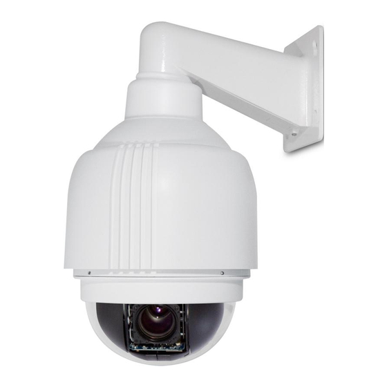
Quick Links
Advertisement
Table of Contents

Related Manuals for Planet ICa-H612


Summary of Contents for Planet ICa-H612
- Page 1 User’s Manual ICA-H612 / ICA-H652 H.264 Outdoor Speed Dome IP Camera - 1 -...
-
Page 2: Ce Mark Warning
Copyright Copyright (C) 2011 PLANET Technology Corp. All rights reserved. The products and programs described in this User’s Manual are licensed products of PLANET Technology, This User’s Manual contains proprietary information protected by copyright, and this User’s Manual and all accompanying hardware, software, and documentation are copyrighted. - Page 3 WEEE as unsorted municipal waste and have to collect such WEEE separately. Trademarks The PLANET logo is a trademark of PLANET Technology. This documentation may refer to numerous hardware and software products by their trade names. In most, if not all cases, their respective companies claim these designations as trademarks or registered trademarks.
-
Page 4: Table Of Contents
TABLE OF CONTENTS Chapter 1 Introduction ......................6 Overview............................... 6 Package Content ............................7 Physical Details ............................8 Camera Substance ..........................8 Switch Identification ..........................8 Chapter 2 Camera Setup and Cable Connections............... 10 Physical Installation Requirement......................10 2.1 System Requirements .......................... 10 2.2 Verify the Contents inside Package Box..................... - Page 5 4.3.9 File Locatioin ........................48 4.3.10 Snapshot .......................... 49 4.3.11 View Log File........................49 4.3.12 View User Information....................50 4.3.13 View Parameters......................51 4.3.14 Factory Default........................ 52 4.3.15 Software Version ......................52 4.3.16 Software Upgrade......................53 4.4 Video and Audio Streaming Settings ....................55 4.4.1 Video Resolution and Deinterlacing Function..............
-
Page 6: Chapter 1 Introduction
H.264 video compression. It is a prefect and effective surveillance solution for the bandwidth limited networks. The ICA-H612 features a 12x12 zooming (12x optical zoom, 12x digital zoom) with auto focus and auto iris, and ICA-H652 features a 36x12 zooming (36x optical zoom, 12x digital zoom) with auto focus and auto iris. -
Page 7: Package Content
3GPP for 3G mobile remote applications, iPhone viewer support Supporting TCP/IP networking, SMTP e-mail and HTTP public network standards, the IP Cam can be applied and utilized to a mixed IP network environment Easy configuration: network administrators can efficiently configure and manage the IP Cam via Windows-Based utility or web interface ... -
Page 8: Physical Details
Physical Details Camera Substance 1. Outdoor Mount 2. Compact Pendent Mount 3. Dome Cover Switch Identification - 8 -... - Page 9 Item Description None Communication Switch (Reserved) RJ45 Connector Data Cable 22-Pin Connector None Reboot Button Factory Reset Button ISP Connector (for FW upgrade) DO NOT change the Speed Dome IP Camera’s Communication Switch factory default settings. Note - 9 -...
-
Page 10: Chapter 2 Camera Setup And Cable Connections
Chapter 2 Camera Setup and Cable Connections Physical Installation Requirement Before installing or connecting the dome camera, please refer to this section and complete preparations for dome setups and various switch settings. 2.1 System Requirements To perform the IP Camera via web browser, please ensure your PC is in good network connection, and meet system requirements as described below for appropriate setup and well view quality. -
Page 11: Physical Installation
Security Tool Lubricant M3/M5 Standard Screw M3/M5 Security Screw AC Power Adapter Quick Installation Guide CD-ROM Power Cord 2.3 Physical Installation 1. During the installation, please take care and avoid crash. That may cause the device damage or cause injury of the installer. Caution 2. - Page 12 STEP 2. Rotate the Outdoor Mount Kit, and take it off from the camera body. STEP 3. Attach the dome cover to the camera body. Before doing that, apply some lubricant on the cover’s water-proof rubber to make the installation process smoother. The tiny protrusion on the dome cover must align with one of the four holes on the dome body.
- Page 13 STEP 5. Use the M3 screw to screw the dome cover and camera body together. STEP 6. Make a cable entry hole on the wall to recess the cables. Otherwise, users could push up the Cable Entry Board on the Compact Pendent Mount’s Mounting Plate to place the cables, as shown in the photo below.
- Page 14 The screws and screw anchors don’t attach in package. Note STEP 8. Attach the Waterproof Rubber to the Outdoor Wall Mount. STEP 9. Pass the network and data cables through the Compact Pendent Mount with the Data Cable’s 22-pin cable coming out of the outlet. 1.
- Page 15 STEP 10. Thread the cables through the Outdoor Mount Kit and join the Outdoor Mount Kit to the Compact Pendent Mount with the supplied screws and washers. Then adjust the Waterproof Rubber to the joint. STEP 11. Use the safety hook hanging the camera, and connect the cables to the Dome Camera. - 15 -...
- Page 16 STEP 12. Join the Dome Camera to the Outdoor Mount Kit with the supplied M5 screw and washers. STEP 13. Connecting power wires of AC adapter with Power Input connector of data cable. Please check the color of power wire carefully, and screwed that with connector properly. - 16 -...
- Page 17 STEP 14. Connecting the AC power adapter with Power Input connector of data cable. Then according to the practical local power voltage to adjust the power switch, and connect the power cord with adapter and power outlet. Use only the power adapter shipped with the unit to ensure correct functionality. Note STEP 15.
-
Page 18: Dome Camera Setups
STEP 17. Use web browser (Internet Explorer 6.0 or above) to connect to 192.168.0.20 (type this address in the address bar of web browser). You’ll be prompted to input user name and password: admin / null (without password). 2.4 Dome Camera Setups Before connecting the IP Camera to other devices of IP Surveillance system, please complete the IP Camera’s ID and communication switch settings. -
Page 19: Communication Switch Setting
None Reboot Button Factory Reset Button ISP Connector (for FW upgrade) DO NOT change the Speed Dome IP Camera’s Communication Switch factory default settings. Note 2.4.2 Communication Switch Setting Communication Switch SW 1 Reserved SW 2 Termination SW 3 Line Lock SW 4 Factory Default Reset SW 5... -
Page 20: 22-Pin Data Cable
2.5.2 22-Pin Data Cable The Speed Dome IP Camera’s Data Cables are illustrated respectively as shown below. 2.5.3 22-Pin Connector Definition With the 22-pin connector, installers can simply connect the power and video cables to the IP Camera at once. Particularly, the alarm pins are serviceable for connecting alarm input and output devices, such as alarm sensors, sirens or flashing lights with the surveillance system. -
Page 21: Chapter 3 Accessing Camera
Chapter 3 Accessing Camera For initial access to the IP Camera, users can search the camera through the installer program: DeviceSearch.exe, which can be found in “DeviceSearch” folder in the supplied CD. 3.1 Device Search Software Setup Step 1: Double click on the program Planet Device Search.exe (see the icon below); its window will appear as shown below. - Page 22 in the figure below. The IP Camera’s default IP address is: 192.168.0.20. Step 4: Double click or right click and select “Browse” to access the camera directly via web browser. Step 5: Then the prompt window of request for entering default username and password (as shown below) will appear for logging in to the IP Camera.
-
Page 23: Example Of Changing Ip Camera's Network Property
NOTE: It is strongly advised that administrator’s password be altered for the security concerns. Refer to section 4.3.2 Security for further details. Additionally, users can change the IP Camera’s network property, either DHCP or Static IP, directly in the device finding list. Refer to the following section for changing the IP Camera’s network property. 3.3 Example of Changing IP Camera’s Network Property Users can directly change an IP Camera’s network property, ex. -
Page 24: Installing Dc Viewer Software Online
Step 3: Click “OK” on the Note of setting change. Wait for one minute to re-search the IP Camera. Step 4: Click the “Device Search” button to search all the devices. Then select the IP Camera with the correct MAC address. Double click on the IP Camera, and the login window will come out. Step 5: Enter User name and Password to access the IP Camera. - Page 25 If the Web browser doesn’t allow DC Viewer installation, please check the Internet security settings or ActiveX controls and plug-ins settings (see Appendix B: Internet Security Settings) to continue the process. The Information Bar (just below the URL bar) may come out and ask for permission to install the ActiveX Control for displaying video in browser (see the figure below).
-
Page 26: Administrator / User Privileges
3.5 Administrator / User Privileges “Administrator” represents the person who can configure the IP Camera and authorize user’s access to the camera; “User” refers to whoever has access to the camera with limited authority, i.e. entering Home and Camera setting pages. - 26 -... -
Page 27: Chapter 4 Configuration & Operation
Chapter 4 Configuration & Operation The IP Camera is provided with a user-friendly browser-based configuration interface, and a free bundled CV3L (Cam Viewer Three Lite Management System) for record and playback video. In this chapter, information about main page introduction, system related settings and camera settings will be described in detail. -
Page 28: Home Page
Streaming setting The administrator can modify video resolution and rotate type and select audio compression mode in this page. PTZ setting Users can adjust various camera parameters such as Exposure, White Balance, Backlight Compensation, etc., and program functions including Preset, Cruise, Auto Pan, Sequence, etc. Logout Click on the tab to re-login the IP Camera with another username and password. - Page 29 shown in the figure below. Left click on either the “Normal View” or “Full screen” tab for setting image display mode. Pan/Tilt Control Users can implement pan/tilt control by first moving the cursor to the live video pane; then left click and drag the pointer in any direction.
- Page 30 Focus Adjustment Auto Focus (Continuous AF): Click on the “auto” button to enable AF mode. In this mode, the camera will keep in focus automatically and continuously regardless of zoom changes or any view changes. The Focus status will also be displayed above the live video pane as shown below. ...
-
Page 31: System Related Settings
4.3 System Related Settings The figure below shows all categories under the “System” tab. Each category in the left column will be explained in the following sections. NOTE: The “System” configuration page is only accessible by the Administrator. - 31 -... -
Page 32: Host Name And System Time Setting
4.3.1 Host Name and System Time Setting Press the first category: <System> in the left column; the page is shown as below. Host Name The name is for camera identification. If Motion Detection function is enabled and is set to send alarm message by Mail/FTP, the host name entered here will display in the alarm message. -
Page 33: Security
Please specify the server you wish to synchronize in the enter field. Then select an update interval from the drop-down menu. For further information about NTP, please see the web site: www.ntp.org. 4.3.2 Security Click the category: <Security>, and the page is shown as the figure below. Root password Change the administrator’s password by inputting the new password in both text boxes. -
Page 34: Network
This item allows the appointed User to change camera parameters on the Camera Setting page. Talk / Listen Talk and Listen functions allow the appointed user in the local site (PC site) communicating with, for instance, the administrator in the remote site. Manage User Delete user To delete a user, pull down the user list, and select the user name you wish to delete. - Page 35 Users can choose to use fixed IP address or dynamic (DHCP) IP address. The following is descriptions for the two ways of setting IP address. Get IP address automatically (DHCP) The camera’s default setting is “Use fixed IP address”. Please refer to the previous section Chapter 3.
- Page 36 When using static IP address to login to the IP Camera, users can access it either through “DeviceSearch” software (see Chapter 3. Accessing Camera) or input the IP address in the URL bar and press “Enter”. General IP address This is necessary for network identification.
-
Page 37: Ddns
Secondary DNS is a secondary domain name server that backups the primary DNS. Web Server port The default web server port is 80. Once the port is changed, the user must be notified the change for the connection to be successful. For instance, when the Administrator changes the HTTP port of the IP Camera whose IP address is 192.168.0.100 from 80 to 8080, the user must type in the web browser “http://192.168.0.100:8080”... -
Page 38: Mail
Enable DDNS Check the item to enable DDNS. Provider Select one DDNS host from the provider list. Host name Enter the registered domain name in the field. Username/E-mail Enter the username or e-mail required by the DDNS provider for authentication. Password/Key Enter the password or key required by the DDNS provider for authentication. -
Page 39: Ftp
Two sets of SMTP can be configured. Each set includes SMTP Server, Account Name, Password and E-mail Address settings. For SMTP server, contact your network service provider for more specific information. 4.3.6 FTP The Administrator can set as sending alarm message to a specific File Transfer Protocol (FTP) site when motion is detected. - Page 40 page. Please refer to the pin definition table below for alarm system wiring. Definition Cable Definition Cable AC 24-1/DC (+) 20AWG ALM-1 ALM NC ALM-3 AC 24-2/DC (-) 20AWG ALM-2 ALM NO ALM-4 20AWG Reserved ALM COM Reserved Audio in Reserved Audio out Reserved...
- Page 41 Alarm Switch The Administrator can enable or disable the alarm function. Alarm Type Select an alarm type, “Normal close” or “Normal open,” that corresponds with the alarm application. Alarm Output Define alarm output signal “high” or “low” as the normal alarm output status according to the current alarm application.
- Page 42 Select this item, and the Administrator can assign a FTP site and configure various parameters as shown in the figure below. When the alarm is triggered, event images will be uploaded to the appointed FTP site. Upload Image by E-Mail Select this item, and the Administrator can assign an e-mail address and configure various parameters as shown in the figure below.
- Page 43 NOTE: Make sure SMTP or FTP configuration has been completed. See section 4.3.5 Mail and 4.3.6 FTP for further details. Function Assign a camera function: Preset, Sequence, Autopan or Cruise, and specify a Preset Point/Sequence Line/Autopan Path/Cruise Line for the camera to perform at an alarm occurrence. NOTE: Please refer to the sections through 4.5.1 Preset Programming to 4.5.4 Sequence Line Programming for details of Preset Point / Sequence Line / Autopan Path / Cruise Line setups.
- Page 44 NOTE: The dwell time is only adjustable when selecting Preset as the alarm action. When the dwell time is up, the Speed Dome IP Camera will go back to its trigger position and recheck alarm pin status. File Name Enter a file name in the blank, ex. image.jpg. The uploaded image’s file name format can be set in this section.
-
Page 45: Motion Detection
The file name suffix will end at the number being set. For example, if the setting is up to “10,” the file name will start from 00, end at 10, and then start all over again. Overwrite The original image in the FTP site will be overwritten by the new uploaded file with a static filename. - Page 46 If Motion Detection function is activated, the pop-off window (Motion) with indication of motion will be shown. When motion is detected, the signals will be displayed on the Motion window as shown below. Detailed settings of Motion Detection are described as follows: Motion Detection You will be able to turn on/off Motion Detection in System section.
- Page 47 Time interval (sec) [0-7200]: The default interval is 10. The value is the interval between each detected motion. Users could adjust the parameter and level of Motion Detection Settings. Sampling pixel interval [1-100]: Default value: 10 Detection level [1-100]: Default value: 10 ...
-
Page 48: File Locatioin
NOTE: Make sure SMTP or FTP configuration has been completed. See section 4.3.5 Mail and 4.3.6 FTP for further details. File Name The uploaded image’s filename format can be set in this section. Please select the one that meets your requirements. -
Page 49: Snapshot
4.3.10 Snapshot The IP Camera supports JPEG snapshot function. Users can specify a storage location for the snapshots. The default setting is: C:\. Once confirm the setting, press “Save,” and all the snapshots will be saved in the designate location. NOTE: Make sure the selected file path contains valid characters such as letters and numbers. -
Page 50: View User Information
4.3.12 View User Information The Administrator can view each added user’s login information and privileges (see 4.3.2 Security). View User Login Information All the users in the network will be listed in the “User information” zone, as shown below. As the figure below shows: User: 4321 It indicates that one user’s login username is: User and the password is: 4321. -
Page 51: View Parameters
As the figure above shows: User: 1:1:0:1 1:1:0:1= I/O access: Camera control: Talk: Listen (see 4.3.2 Security) Therefore, it denotes the user is granted privileges of I/O access, Camera control and Listen. 4.3.13 View Parameters Click on this item to view the entire system’s parameter setting. - 51 -... -
Page 52: Factory Default
4.3.14 Factory Default The factory default setting page is shown as below. Follow the instructions to reset the IP Camera to factory default setting if needed. Set Default Click on the “Set Default” button to recall the factory default settings. Then the system will restart in 30 seconds. -
Page 53: Software Upgrade
4.3.16 Software Upgrade Software upgrade can be carried out in the “Software Upgrade” page as shown below. NOTE: Make sure the upgrade software file is available before carrying out software upgrade. The procedure of software upgrade is like the following: Step 1: Click “Browse”... - Page 54 NOTE: Do not change the upgrade file name, or the system will fail to find the file. Step 2: Pull down the upgrade binary file list and select the file you want to upgrade; in this case, select “userland.jffs2.” Step 3: Press “Upgrade”. The system will first check whether the upgrade file exists or not, and then begin to upload the upgrade file.
-
Page 55: Video And Audio Streaming Settings
Step 5: Click “Control Panel”, and then double click “Add or Remove Programs.” In the “Currently install programs” list, select “DCViewer” and click the button “Remove” to uninstall the existing DC Viewer. Step 6: Open a new web browser, re-login the IP Camera, and then allow the automatic download of DC Viewer. -
Page 56: Video Compression
Video Resolution The IP Camera provides various video resolutions like the following: H.264 D1 (25fps) + MJPEG D1 (25fps) H.264 D1 (25fps) + MJPEG CIF (25fps) H.264 D1 (25fps) + H.264 D1 (25fps) H.264 D1 (25fps) + H.264 CIF (25fps) Text Overlay Settings Users can select the items to display data including date/time/text on the live video pane. -
Page 57: Video Ocx Protocol
high compression, low bitrate, low quality middle compression, default low compression, high bitrate, high quality H.264 compression settings include: highest compression, lowest quality middle compression, default low compression, highest quality Users can also decide whether to display compression information on the Home page. Click “Save”... -
Page 58: Video Frame Skip
4.4.4 Video Frame Skip Video frame skipping is for saving bandwidth if necessary. The setting page is shown as below. MJPEG/H.264 Frame Skip options include: No skipping, default Frame skipping at 5 frame internal (lowest frame loss rate) ... -
Page 59: Ptz Settings
Half-duplex (Talk or Listen, not at the same time) In the Half-duplex mode, the local/remote site can only talk or listen to the other site at a time. Simplex (Talk only) In the Talk only Simplex mode, the local/remote site can only talk to the other site. ... -
Page 60: Cruise
Preset Setting To setup a Preset Point, please first move the cursor to the live view pane. Then left click and drag the red pointer with PTZ controls to a desired position. Subsequently, assign a number for the current position from the drop-down Number List, and enter its descriptive name. Press the button “Set” to save the settings mentioned above. -
Page 61: Auto Pan
Cruise Setting To setup a Cruise Path, please first select a path number from the drop-down list. Then move the cursor to the live view pane, and move the camera to a desired view (PTZ controls) as the start point of a Cruise Path. -
Page 62: Sequence
NOTE: The room ratio of an Auto Pan’s Start Point will persist throughout the whole path. Enter the speed ratio into the Speed field; the speed ratio ranges from 0 (low) to 3 (fast). Then choose to run the Auto Pan Path in right/left direction from the Direction drop-down list. Move the camera to another desired position as the end point of the Auto Pan Path. - Page 63 shown in the next page. Sequence Line Please select the number of Sequence Line to be set from the drop-down list in the top of the Sequence setting menu. Sequential Preset Points Setting Please setup each Preset Point of the programmed Sequence Line in order, assigning a Preset Point from the “Name”...
-
Page 64: Home
4.5.5 Home Users are able to set an operation mode to ensure constant monitoring. If the Speed Dome IP Camera idles for a period of time, the selected function will be activated automatically; this is the HOME function. The HOME function allows constant and accurate monitoring to avoid the Dome Camera idling or missing events. -
Page 65: Privacy Mask
button to save the tilt angle settings. 4.5.7 Privacy Mask The Privacy Mask function aims to avoid any intrusive monitoring. When setting a mask, it is suggested to set it at least twice bigger (height and width) than the masked object. The Speed Dome IP Camera will assume the center of the selected view as a starting point. -
Page 66: Camera - Exposure
will be disabled automatically while the Privacy Mask function is enabled. Mask Setting Activate/Disable Privacy Mask Function The Privacy Mask function can be activated or disabled. Press the button “Set” to save the setting. Activate/Disable Transparency Mask The Privacy Mask can be set as transparency if necessary. ... -
Page 67: Camera - Wb
Shutter Priority Mode In this mode, it is shutter speed that takes main control of exposure. The range of shutter speed is from 1/10000 ~ 1. Gain The bright value ranges from 1 ~ 15. 4.5.9 Camera - WB A camera needs to find reference color temperature, which is a way of measuring the quality of a light source, for calculating all the other colors. -
Page 68: Camera - Miscellaneous Setups Menu 1
Light Sources Color Temperature in K Cloudy Sky 6,000 to 8,000 Noon Sun and Clear Sky 6,500 Household Lighting 2,500 to 3,000 75-watt Bulb 2,820 Candle Flame 1,200 to 1,500 Auto Mode In this mode, white balance works within its color temperature range and calculates the best-fit white balance. - Page 69 Users can choose to activate or disable the BLC function. Press the button “Set” to save the setting. Sharpness Increasing the sharpness level can make the image looked sharper; especially enhancing the object’s edge. The Sharpness value is adjustable from 1 to 15. Press the button <Set> to confirm the setting. ExpComp Users can define the value of Exposure Compensation;...
-
Page 70: Camera - Miscellaneous Setups Menu 2
the setting. ICR Function With the IR cut filter, the camera can still catch clear image at night time or in low light conditions. Auto In the Auto mode, the internal circuit will automatically decide the occasion to remove the IR cut filter according to the image brightness level. -
Page 71: Camera - Default
With the Auto Calibration function, the Speed Dome IP Camera calibrates when the deviation of dome pivot is detected. Press the button “Set” when finishing setting. The WDR function is especially effective in environment with extreme contrast. Press the button “Set” when finishing the setting. - Page 72 - 72 -...
-
Page 73: Appendix A: Ip Camera Specifications
Appendix A: IP Camera Specifications Product ICA-H612 Video Specification Horizontal Resolution 540 TV Lines Scanning System NTSC / PAL NTSC 380K: 768 (H) x 494 (V) Effective Pixels PAL 440K: 752 (H) x 582 (V) Sensor 1/4” Color Sony CCD... - Page 74 Pan Degree 0 ~ 360 degree continuous panning Tilt Degree 90 degree with instant flip Preset Point 256 present points Camera Cruise 8 cruises Audio in / Audio out 1 x MIC in / 1 x Line out Video Output 1.0 Vp-p / 75ohm (BNC connector) 2-Way Audio Full-duplex, Half-duplex, Simplex...
- Page 75 Video Encoder H.264 / M-JPEG simultaneously D1: NTSC 720x480 / PAL 720x576 Video Resolution CIF: NTSC 352x240 / 352x288 Frame Rate 30fps for all resolutions Audio Compression G.726 ADPCM / AAC Alarm Reaction Preset, Sequence, Auto pan, Cruise Network and Configuration Network Interface Ethernet 10Base-T/100Base-TX Networking Protocol...
-
Page 76: Appendix B: Internet Security Settings
Appendix B: Internet Security Settings If ActiveX control installation is blocked, please either set Internet security level to default or change ActiveX controls and plug-ins settings. Internet Security Level: Default Step 1: Start the Internet Explorer (IE). Step 2: Select <Tools> from the main menu of the browser. Then Click <Internet Options>. Step 3: Click the <Security>... - Page 77 ActiveX Controls and Plug-ins Settings Refer to the previous section above. Step 1~3: Step 4: Down the page, press “Custom Level” (see the figure below) to change ActiveX controls and plug-ins settings. The Security Settings screen is displayed as below: - 77 -...
- Page 78 Step 5: Under “ActiveX controls and plug-ins”, set ALL items (as listed below) to <Enable> or <Prompt>. ActiveX controls and plug-ins settings: 1. Automatic prompting for ActiveX controls 2. Binary and scrip behaviors 3. Download signed ActiveX controls 4. Download using ActiveX controls 5.
-
Page 79: Appendix C: Dc Viewer Download Procedure
Appendix C: DC Viewer Download Procedure The procedure of DC Viewer software download is specified as follows. Step 1: In the DC Viewer installation page, click “Next” for starting installing. Step 2: Setup starts. Please wait for a while until the loading bar runs out. - 79 -... - Page 80 Step 3: Click “Finish” to close the DC Viewer installation page. Then, the IP Camera’s Home page will display as follows: - 80 -...
-
Page 81: Appendix D: Frequently Asked Questions
Appendix D: Frequently Asked Questions [ICA-H612/ICA-H652] How can I know the IP address of IP camera? The default IP address is 192.168.0.20, and you could use the Device Search utility on the bundled CD to obtain the current IP address of IP camera. Please refer to the user’s manual Ans: for more detail information. -
Page 82: Ec Declaration Of Conformity
*Type of Product: *Model Number: ICA-H652-NT/PA * Produced by: Manufacturer‘s Name : Planet Technology Corp. Manufacturer‘s Address: 11F, No 96, Min Chuan Road, Hsin Tien, Taipei, Taiwan, R.O.C. is herewith confirmed to comply with the requirements set out in the Council Directive on the Approximation of the Laws of the Member States relating to Electromagnetic Compatibility (89/336/EEC,).
Need help?
Do you have a question about the ICa-H612 and is the answer not in the manual?
Questions and answers