Planet ICA-HM316W User Manual
2mega-pixel 11n outdoor ir ip camera
Hide thumbs
Also See for ICA-HM316W:
- User manual (70 pages) ,
- Quick installation manual (20 pages) ,
- Quick installation manual (32 pages)
Table of Contents
Advertisement
Quick Links
Advertisement
Table of Contents

Related Manuals for Planet ICA-HM316W


Summary of Contents for Planet ICA-HM316W
- Page 1 User’s Manual ICA-HM316W 2Mega-Pixel 11n Outdoor IR IP Camera...
- Page 2 Copyright Copyright 2011 by PLANET Technology Corp. All rights reserved. No part of this publication may be reproduced, transmitted, transcribed, stored in a retrieval system, or translated into any language or computer language, in any form or by any means, electronic, mechanical, magnetic, optical, chemical, manual or otherwise, without the prior written permission of PLANET.
- Page 3 Do not dispose of WEEE as unsorted municipal waste and have to collect such WEEE separately. Revision User’s Manual for PLANET 2Mega-Pixel 11n Outdoor IR IP Camera Model: ICA-HM316W Rev: 1.00 (May. 2011) Part No. EM-ICAHM316W...
-
Page 4: Table Of Contents
1.3 Package Contents..................... 7 Basic Setup ....................... 8 2.1 System Requirements..................8 2.2 Physical Description..................9 2.2.1 Identification of ICA-HM316W cable ........... 9 2.2.2 ICA-HM316W I/O Control Instruction..........10 2.3 Hardware Installation ..................12 2.3.1 Physical Installation ................12 2.4 Initial Utility Installation ................... 13 2.4.1 Search and Configure Network by PLANET IP Installer .... - Page 5 Appendix B: PING IP Address..................53 Appendix C: 3GPP Access ................... 54 Appendix D: Bandwidth and Video Size Estimation ..........55 Appendix E: DDNS Application ..................56 Appendix F: Configure Port Forwarding Manually ............ 61 Appendix : Troubleshooting & Frequently Asked Questions ........ 64 Appendix : Product Specification................
-
Page 6: Introduction
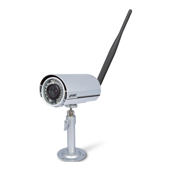
1. Introduction PLANET ICA-HM316W the new 2 Mega-Pixel 11n Outdoor IR IP Camera is to fulfill the demands in worldwide surveillance market. The ICA-HM316W supports the highest video compression – H.264, which provides small video size and save you lots of bandwidth usage. -
Page 7: Package Contents
1.3 Package Contents The package should contains the followings: IP Camera Unit x 1 Power Adapter x 1 Screw package x 1 Stand x 1 5dbi Antenna x 1 User’s Manual CD-ROM x 1 Quick Installation Guide x 1 1. If any of the above items are missing, please contact your dealer immediately. NOTE: 2. -
Page 8: Basic Setup
2. Basic Setup This chapter provides details of installing and configuring the Internet camera 2.1 System Requirements Network Interface 10/100Base-TX Ethernet Monitoring System Recommended for Internet Explorer 6.0 or later · CPU: Intel Dual Core 1.66G System Hardware · Memory Size : 1024 MB (1024 MB or above Recommended ) (Suggested) ·... -
Page 9: Physical Description
2.2 Physical Description 2.2.1 Identification of ICA-HM316W cable 1. RJ-45 LAN socket: Connect to PC or Hub/Switch. For connect to 10Base-T Ethernet or 100Base-TX Fast Ethernet cabling. This Ethernet port built N-Way protocol can detect or negotiate the transmission speed of the network automatically. -
Page 10: Ica-Hm316W I/O Control Instruction
2.2.2 ICA-HM316W I/O Control Instruction 1. Digital Input (GND + Alarm) An alarm input for connecting devices that can toggle between an open and closed circuit, for example: PIRs, door/window contacts, glass break detectors, etc. When a signal is received the state changes and the input becomes active. - Page 11 2. Relay Output Connection...
-
Page 12: Hardware Installation
2.3 Hardware Installation 2.3.1 Physical Installation 1. Connect an Ethernet cable Connect the LAN cable on the camera to the network device (hub or switch). 2. Attach the power supply Plug in power adapter and connect to power source. After power on, the camera will start to operate. -
Page 13: Initial Utility Installation
2.4 Initial Utility Installation This chapter shows how to quick set up your H.264 camera. The camera is with the default settings. However to help you find the networked camera quickly the windows utility PLANET IP Installer can search the cameras in the network that shall help you to configure some basic setting before you started advanced management and monitoring. - Page 14 3. The GUI of IP Installer is as follows (Default IP: 192.168.0.20). (1) IP Installer will search all IP Cameras connected on LAN. The user can click “Search Device” to search again. (2) Click one of IP Cameras listed on the left side of IP Installer, then the network configuration of that IP Camera will be listed on the right side.
- Page 15 (3) Please make sure the subnet of PC IP address and IP CAM IP address are the same. IP CAM IP address: 192.168.0.20 PC IP address: 192.168.0.100 (4) Different Subnets: IP CAM IP address: 192.168.0.20 PC IP address: 192.168.1.100 (5) To Change PC IP address: Control PanelNetwork ConnectionsLocal Area Connection PropertiesInternet Protocol (TCP/IP) Properties Please make sure your IP Camera and PC have the same Subnet.
- Page 16 (8) If the user name and password are input correctly, the following web page will be displayed.
-
Page 17: Setup Activex To Use The Internet Camera
2.5 Setup ActiveX to use the Internet Camera The Internet camera web pages communicate with the Internet camera using an ActiveX control. The ActiveX control must be downloaded from the Internet camera and installed on your PC. Your Internet Explorer security settings must allow for the web page to work correctly. To use the Internet camera, user must setup his IE browser as follows: 2.5.1 Internet Explorer 6 for Windows XP ... -
Page 18: Internet Explorer 7 For Windows Xp
2.5.2 Internet Explorer 7 for Windows XP From your IE browse ”Tools” ”Internet Options…” ”Security” ”Custom Level…”, please setup your “Settings” as follow. Set the first 3 items • Allow previously unused ActiveX control to run… • Allows Script lets •... -
Page 19: Internet Explorer 7 For Windows Vista
2.5.3 Internet Explorer 7 for Windows Vista From your IE browse ”Tools” ”Internet Options…” ”Security” ”Internet” ”Custom Level…”, please setup your “Settings” as follow. • Enable “Automatic prompting for ActiveX controls” • Prompt “Initialize and script active controls not marked….” From your IE browse ... -
Page 20: Web-Based Management
3. Web-based Management This chapter provides setup details of the Internet camera’s Web-based Interface. 3.1 Introduction The Internet camera can be configured with your Web Browser. Before configure, please make sure your PC is under the same IP segment with Internet camera. 3.2 Connecting to Internet Camera Use the following procedure to establish a connection from your PC to the camera. - Page 21 Web browser may display the “Security Warming” window, select “Yes” to install and run the ActiveX control into your PC. After the ActiveX control was installed and run, the first image will be displayed. If you log in the camera as an ordinary user, setting function will be not available. If NOTE: you log in the camera as the administrator, you can perform all the settings provided within the device.
-
Page 22: Live View
4. Live View Start-up screen will be as follow no matter an ordinary users or an administrator. Get into the administration page. (1)Configure .Video Snapshot (2)Snapshot Show system time, video resolution, and video refreshing rate. (3)Status Bar Select video screen “default, 1/2x, 1x, 2x” for view currently (4)Screen Size camera screen size. - Page 23 Shows how many people connect to this IP camera. (7)Online Visitor Control the relay which is connected to this camera. (8)Relay Control Double-click the video; it will change to full screen mode. Press “Esc” or double-click the video again, it will change back to normal mode. Right-Click the mouse on the video, it will show a pop-up menu.
-
Page 24: Configuration
5. Configuration Click to get into the administration page. Click to go back to the live video page. -
Page 25: System
5.1 System 5.1.1 System Information 1. Server Information: Set up the camera name, select language, and set up the camera time. This is the Camera name. This name will show on the IP Server Name Installer. There are English, Traditional Chinese, Simplified Chinese, French, Russian, Italian, Spanish, German, Portuguese and Polish to select. - Page 26 Server time setting:Select options to set up time - “NTP”, “Synchronize with PC’s time”, “Manual”, “The date and time remain the same”.
-
Page 27: User Management
5.1.2 User Management IP CAMERA supports three different users, administrator, general user, and anonymous user. Yes:Allow anonymous login Anonymous User Login No:Need user name & password to access this IP camera Type the user name and password, then click “Add/Set”. Add user Click “edit”... -
Page 28: System Update
5.1.3 System Update To update the firmware online, click “Browse…” to select the Firmware Upgrade firmware. Then click “Upgrade” to proceed. Re-start the IP camera. Reboot System Delete all the settings in this IP camera. Factory default User may download the current setting to PC, or upgrade from Setting Management previous saved setting. -
Page 29: Network
5.2 Network 5.2.1 IP Setting IP Camera supports DHCP and static IP. Using DHCP, IP Camera will get all the network parameters DHCP automatically. Please type in IP address, subnet mask, gateway, and DNS Static IP manually. User may need to assign different port to avoid conflict when setting up IP assignment. -
Page 30: Using Upnp Of Windows Xp Or Vista
This IP camera supports UPnP, If this service is enabled on your computer, the camera will automatically be detected and a new UPnP icon will be added to “My Network Places.” Note: UPnP must be enabled on your computer. Please follow the procedure to activate UPnP 5.2.2 Using UPnP of Windows XP or Vista 5.2.2.1 Windows XP UPnP™... - Page 31 The “Control Panel” will display on the screen and double click “Add or Remove Programs” to continue The “Add or Remove Programs” will display on the screen and click Add/Remove Widows Components to continue.
- Page 32 The following screen will appear, select “Networking Services” and click “Details” to continue The “Networking Services” will display on the screen, select “Universal Plug and Play” and click “OK” to continue.
- Page 33 Please click “Next” to continue The program will start installing the UPnP automatically. You will see the below pop-up screen, please wait while Setup configures the components.
- Page 34 Please click “Finish” to complete the UPnP installation Double-click “My Network Places” on the desktop, the “My Network Places” will display on the screen and double-click the UPnP icon with Internet camera to view your device in an Internet browser.
-
Page 35: Windows Vista
5.2.2.2 Windows Vista UPnP™ is short for Universal Plug and Play, which is a networking architecture that provides compatibility among networking equipment, software, and peripherals. This device is an UPnP enabled device. If the operating system, Windows Vista, of your PC is UPnP enabled, the device will be very easy to configure. - Page 36 Double-click “My Network Places“ on the desktop, the “My Network Places” will display on the screen and double-click the UPnP icon with Internet camera to view your device in an Internet browser.
-
Page 37: Pppoe
5.2.3 PPPoE PPPoE: Stands for Point to Point Protocol over Ethernet A standard builds on Ethernet and Point-to-Point network protocol. It allows Internet camera connect to Internet with xDSL or cable connection; it can dial up your ISP and get a dynamic IP address. - Page 38 IP address is when you want to access your network over the Internet. The solution to the dynamic IP address problem comes in the form of a dynamic DNS service. The Internet uses DNS servers to lookup domain names and translates them into IP addresses. Domain names are just easy to remember aliases for IP addresses.
- Page 39 Camddns, the procedures are: (1) Please enable this service (2) Key-in user name. (3) IP Schedule update is default at 5 minutes (4) Click “Apply”. DDNS Status (1) Updating:Information update (2) Idle:Stop service (3) DDNS registration successful, can now log by http://<username>.ddns.camddns.com: Register successfully.
-
Page 40: Mail & Ftp
5.2.5 Mail & FTP To send out the video via mail of ftp, please set up the configuration first. 5.2.6 Wireless Setting... - Page 41 ●Wireless Setting There are Infrastructure and Ad-hoc. Infrastructure is for connecting with the router. Ad-hoc is for connecting with PC. There is “Channel” to select Mode only when user uses Ad-hoc mode. e.g. If one PC’s channel is 1, the other’s channel has to 1, too. Based on AP setting.
-
Page 42: A/V Setting
5.3 A/V Setting 5.3.1 Image Setting For the security purpose, there are three areas can be setup for privacy mask. Click “Area” button first and pull an area on the above image. Finally, click “Save” button to reserve the setting. Adjust “Brightness”, “Contrast”, “Hue”, “Saturation”... - Page 43 Max Video Frame Rate for both streaming combined is 30 FPS. NOTE: Video System: click the drop down list to select the system type “NTSC/PAL”. Streaming 1 and 2Basic Mode: There are 8 resolutions can be chosen. 1600x 1200, 1280x1024, 1280x960, 1280x720, 800x600, Resolution 640x480, 320x240, 176x144 There are 5 levels to adjust:...
- Page 44 Streaming 1 and 2 Advanced Mode: There are 8 resolutions can be chosen. 1600x 1200, 1280x1024, 1280x960, 1280x720, 800x600, Resolution 640x480, 320x240, 176x144 There are CBR﹝Constant Bit Rate﹞ and VBR﹝Variable Bit Rate﹞to use. CBR:32Kbps~4Mbps (the higher the CBR is, the better the video quality is) Bitrate Control Mode VBR:1(Low) ~10(High) –...
-
Page 45: Audio
NOTE: 5.3.3 Audio The ICA-HM316W supports 2-way audio. User can send audio from ICA-HM316W Built-in mic to remote PC; User can also send audio from remote PC to ICA-HM316W’s external speaker. (1) Audio from IP camera built-in mic to local PC: select “Enable” to start this function. -
Page 46: Event List
5.4 Event List The ICA-HM316W provides multiple event settings. 5.4.1 Event Setting... -
Page 48: Schedule
IP CAMERA allows 3 areas motion detection. When motion is triggered, it can send the video to some specific mail addresses, transmit the video to remote ftp server and SAMBA, trigger the Motion Detection relay. To set up the motion area, click “Area Setting”. Using mouse to drag and draw the area. -
Page 49: I/O Setting
5.4.3 I/O Setting The ICA-HM316W supports 1 input/ 1 output. When input is triggered, it can send the video to some specific mail addresses, transmit the video to remote ftp server, trigger the relay and SAMBA. Please connect to propriety relay box to reduce the risk of electric shock & damaged. - Page 50 By GPIO I/O port input that provides related action while I/O Alarm Input Setting input triggered. By GPIO I/O port output that provides OnOff Switch, Slide GPIO Output Setting Switch & Pan/Tilt Module for using with relay box. GPIO pin define please refer to the part of Front / Back plane & I/O port pin assignment. GPIO 0 ALARM INPUT Normal: 3.3V (The voltage differential from GPIO pin &...
-
Page 51: Log List
GPIO INSTALLATION EXAMPLE 2 Trigger the normal on (Normal Close) indoor illumination off when event / motion occur at COM: 5.4.4 Log List Sort by System Logs, Motion Detection Logs and I/O Logs. In addition, System Logs and I/O Logs won’t lose data due to power failure. -
Page 52: Appendix A: Factory Default
4. When camera starts again, please wait 10 seconds, then remove the pink default cable. 5. Then unplug the power, after 5sec, re-plug the power and plug Ethernet cable. 6. Use the IPInstaller utility to search your ICA-HM316W. 7. Re-login the camera using the default IP (http://192.168.0.20), and user name (admin),... -
Page 53: Appendix B: Ping Ip Address
Appendix B: PING IP Address The PING (stands for Packet Internet Groper) command is used to detect whether a specific IP address is accessible by sending a packet to the specific address and waiting for a reply. It’s also a very useful tool to confirm Internet camera installed or if the IP address conflicts with any other devices over the network. -
Page 54: Appendix C: 3Gpp Access
Appendix C: 3GPP Access To use the 3GPP function, in addition to previous section, you might need more information or configuration to make this function work. That to use the 3GPP function, it strongly recommends to install the Networked Device Note: with a public and fixed IP address without any firewall protection. -
Page 55: Appendix D: Bandwidth And Video Size Estimation
Appendix D: Bandwidth and Video Size Estimation The frame rate of video transmitted from the Internet camera depends on connection bandwidth between client and server, video resolution, codec type, and quality setting of server. Here is a guideline to help you roughly estimate the bandwidth requirements for your Internet camera. The required bandwidth depends on content of video source. -
Page 56: Appendix E: Ddns Application
Appendix E: DDNS Application 1. Preface If you have a Cable modem or xDSL, this is a great way to host your own Networked Device or other TCP/IP Service. Get your own domain like www.yourname.com, www.yourname.com.tw etc. (Note: This domain must be registered with Internic via registration authorities such as Network Solutions, DirectNIC, Register.com etc). - Page 57 (3). After the columns show up at the left side, click “Create Account”. (4). Fill the application agreement and necessary information. a. Username b. E-mail address and confirmation c. Password and confirmation d. Submit all the input information and finish creating an account...
- Page 58 Click these two options (5). Check your e-mail mailbox. There will be an e-mail with a title “Your DynDNS Account Information“. Click the hyperlink address to confirm the DDNS service that you just applied. Then DDNS you applied activated. Click to confirm...
- Page 59 (6). Enter the web page http://www.dyndns.org/ again. Input your username and password that you just applied to login administration interface of DDNS server. Input your account (7). If the correct username and password are input, you can see the following picture at the top-right of the login page.
- Page 60 (9). Click the “ Dynamic DNS ”. (10). Click the “Create Hosts”. (11). We could create a domain name without any charge at this step. First, we input the host name. (No.1) Then we pick a domain that is easy to remember. Finally (No.2), click the “Add Host”...
-
Page 61: Appendix F: Configure Port Forwarding Manually
Appendix F: Configure Port Forwarding Manually The device can be used with a router. If the device wants to be accessed from the WAN, its IP address needs to be setup as fixed IP address, also the port forwarding or Virtual Server function of router needs to be setup. - Page 62 Your WAN IP Address will be listed here. 3. Open/set Virtual Server Ports to enable remote image viewing The firewall security features built into the router and most routers prevent users from accessing the video from the device over the Internet. The router connects to the Internet over a series of numbered ports.
- Page 63 Some ISPs block access to port 80. Be sure to check with your ISP so that you can NOTE: open the appropriate ports accordingly. If your ISP does not pass traffic on port 80, you will need to change the port the camera uses from 80 to something else, such as 8080. Not all routers are the same, so refer to your user manual for specific instructions on how to open ports.
-
Page 64: Appendix : Troubleshooting & Frequently Asked Questions
Appendix Troubleshooting & Frequently Asked Questions Features The device utilizes H.264, MPEG-4 and M-JPEG triple compression to providing high quality images. Where H.264 and MPEG-4 are standards for video compression and M-JPEG is a standard for The video and audio codec is image compression. - Page 65 Antivirus software on the PC might interfere with the setup program. Disable the firewall of the antivirus software during setting up this device. Check the firewall setting of your PC or Notebook. Make sure that your Internet Explorer is version 6.0 or later. If you Internet Explorer does not seem to are experiencing problems, try upgrading to the latest version of work well with the device...
- Page 66 manual for details. Packet Filtering of the router may prohibit access from an external network. Refer to your router's manual for details. Access the Network Camera from the Internet with the global IP address of the router and port number of Network Camera. Some routers reject the global IP address to access the Network ...
- Page 67 Use the operating system of the selected language. Set the The unreadable characters are Encoding or the Character Set of the selected language on the displayed. Internet Explorer. The traffic of the network and the object of the image affect the ...
-
Page 68: Appendix : Product Specification
Appendix : Product Specification Camera Specification 1/3.2” 2Mega-Pixel CMOS Sensor Image Device 1600 x 1200 pixels Effective Pixels 0.5lux Sensitivity 3.6 ~ 16mm Vari-focal lens with auto iris and IR cut filter/ F1.2 Lens 0 Lux IR on Illuminator H: 20.8~75.4 Degree / V: 15.7~54.9 Degree View Angle Video Specification H.264, MPEG4 and Motion JPEG simultaneously (Tri-encoders) - Page 69 OFDM: 14 dBm Output Power CCK: 17 dBm 11b→1M:-90 11M:-85 11g→6M:-87 54M:-70 Receiver Sensitivity 11n(BW20)→MCS0:-85 MCS7:-67 11n(BW40)→MCS0:-84 MCS7:-64 IEEE802.11b Standard Data Rates: 1, 2, 5.5 and 11Mbps IEEE802.11g Standard Data Rates: 6, 9, 12, 18, 24, 36, 48, 54Mbps IEEE802.11n Standard Data Rates: Legacy and High Throughput Data Rate Modes, Support 20/40MHz Bandwidth MCS0~7(150Mbps PHY Rate Rate)
Need help?
Do you have a question about the ICA-HM316W and is the answer not in the manual?
Questions and answers