
Summary of Contents for Goldline Pro LOGIC PL-P-4
- Page 1 Automation and Chlorination Installation Manual for model PL-P-4 LINE ON TROLS www.goldlinecontrols.com...
-
Page 2: Important Safety Instructions
IMPORTANT SAFETY INSTRUCTIONS When using this electrical equipment, basic safety precautions should always be followed, including the following: READ AND FOLLOW ALL INSTRUCTIONS • • WARNING: Disconnect all AC power during installation. • WARNING: Water in excess of 100 degrees Fahrenheit may be hazardous to your health. -
Page 3: Table Of Contents
Introduction 1. Preparing Pool/Spa Water 2. Mounting Equipment 3. Plumbing 4. Electrical Wiring 5. Configuration 6. System Startup and Checkout 7. Warranty Pro Logic Limited Warranty...32 Before You Begin... 1 Installation Steps... 2 General Water Chemistry... Salt... 3 Pro Logic Control Center... 5 Temperature Sensors... -
Page 4: Introduction Before You Begin
Before You Begin What’s Included Before attempting to install the Pro Logic system, check that the following components have been included in the package: Pro Logic Electronics Unit (3) Temperature sensors with 15 ft. (5m) cable, hose clamp What’s NOT Included Some of the additional items that you may need to complete an installation include: Circuit breakers None are included with control—see page 10 and inside of door for suitable breakers... -
Page 5: Preparing Pool/Spa Water
4. Electrical Wiring (page 10) Main service Grounding and bonding Circuit breakers Pro Logic control power High Voltage pool equipment Low voltage wiring (temperature sensors, flow switch, etc.) 1. Preparing Pool/Spa Water General Water Chemistry Salt is required only if you are using the chlorinator features on the Pro Logic Control. If you are NOT using the chlorinator, it is recommended that you follow all of the other chemistry recommendations besides salt. -
Page 6: Salt Level
The pool’s chemistry must be balanced BEFORE activating the Pro Logic’s optional chlorinator function. NOTE: If the pool does not have new water, add metal remover and non-copper based algaecide to the pool, per manufacturer’s instructions. This ensures a quick, troublefree transfer to the Pro Logic system. Salt (When using optional chlorinator function ) Salt Level... - Page 7 Rectangular Round Oval Type of Salt to Use It is important to use only sodium chloride (NaCl) salt that is greater than 99.0% pure. This can be found at most pool stores in 40-80 lb. bags labeled “for use in swimming pools”. Alternatively, use common food quality or water softener salt that is at least 99.0% pure.
-
Page 8: Mounting Pro Logic Control Center
The PL-P-4 model requires the use of a chlorinator cell and plumbing kit to provide pool chlorination. These items are not included with the Pro Logic and can be purchased separately at your local Goldline dealer. Choose a chlorinator cell model based on the size of your pool. The following models are available:... -
Page 9: Optional Aql-Chem2 Co
Pro Logic. Refer to the AQL-CHEM2 manual for specific installation information. Optional Remote Controls Goldline offers a variety of wired and wireless remote control options for the Pro Logic. Each model gives you the ability to control your pool’s functions from a remote location, away from the Control Center. -
Page 10: Optional Base Station
Note that the Pro Logic is compatible with AQL2 wireless remote controls only. A single AQL2-BASE-RF Base Station must be installed on the Pro Logic in order to use any of the Goldline wireless remote controls. With the Base Station installed, there is no limit on the number of wireless remotes that can used. The maximum distance between the wireless remotes and the base station on the Pro Logic main control unit is 400 feet (120m) line of sight or 200 feet (60m) through walls, etc. -
Page 11: Plumbing Pool/Spa Configuration
Pool/Spa system configuration These systems use a single filter pump and filter. Pool or spa operation is controlled by two 3-way valves (suction and return). Refer to the diagram below. High Voltage Relays Filter Pump Lights Aux 1 Aux 2 MANUAL VALVE POOL/SPA SUCTION... -
Page 12: Turbo Cell
Turbo Cell (choose proper model for your pool) The Turbo Cell (used for chlorine generation) should be plumbed AFTER the filter and heater. If installed on a pool/ spa combination system, the cell should be plumbed BEFORE the pool/spa return valve in order to allow proper chlorination of both the pool and the spa. -
Page 13: Electrical Main Service
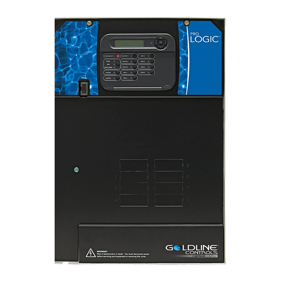
Remote Keypad Temp Sensor Inputs External Input Heater Output Valve Connectors Flow Switch Cell Connector Subpanel The Pro Logic Control Center requires both high and low voltage connections. Low voltage connections will be made to actuators, sensors, remote keypad, etc. High voltage connections will be made to pumps, lights, etc., as well as providing direct input power to the Control Center. -
Page 14: General Purpose Outlet
General Purpose Outlet If desired, a duplex receptacle with weatherproof cover (supplied by installer) may be installed in the knockouts on the lower right side of the Pro Logic enclosure. Per code, the receptacle should be a GFCI type. Alternatively, connect a standard receptacle to a GFCB. - Page 15 Goldline pH Dispense Output: NOTE: The Pro Logic can only be used with a 120VAC pH dispensing device. There are two Pro Logic versions that require different installation techniques. Pro Logics operating with a software version less than 4.00 require the pigtail or pH dispensing device to be connected to an internal relay.
-
Page 16: Low Voltage Wiring
(Valve2) and return (Valve1) valves. Valve3 is for general purpose use (solar, water feature, in-floor cleaner, etc.). For installations with solar heating, Goldline offers the AQ-SOL-KIT-xx solar kit that contains a valve, actuator, and extra temperature sensor. The “xx” indicates the valve type from the 3 choices below: 1.5”... - Page 17 Laars Heaters 1. Turn power off to heater. 2. Remove factory jumper from terminal block. 3. Wire Pro Logic to the heater as shown. 4. Ensure toggle switch is in the ON position. 5. Set heater thermostats to maximum position. to limit switches white white...
- Page 18 Pentair/Purex/MiniMax 1. Turn power off to heater. 2. Remove factory installed jumper from the “Ext Switch” connector. 3. Wire the Pro Logic to the “Ext Switch” connector as shown below. 4. The wires to the Pro Logic must be separated from any line voltage wires. Failure to follow these instructions may cause erratic operation of the heater.
- Page 19 STA-RITE Heater 1. Turn power off to heater. 2. Remove upper jacket and open the control box. 3. Remove the jumper for the “fireman’s switch. 4. Wire to the Pro Logic using wire rated for 105°C minimum. Fireman’s Switch Operating ‘Control Terminal Board...
- Page 20 VSC Pump Address Setting For proper communications, a pump address must be set for each VSC used in the system. For single pump systems, the VSC address should be set to 001. When using Dual Equipment, the Pool Filter pump should be set to 001 and the Spa Filter pump should be set to 002.
-
Page 21: Base Station
Base Station Plug in the pigtail connector from the wireless base station into the “wireless” connector on the main PCB in the Pro Logic control unit. Base Station (AQL2-BASE-RF) Tighten nut AQL-CHEM ORP and pH Sensing Kit Plug in the connector from the AQL-CHEM into one of the “COMM” connectors on the main PCB in the Pro Logic control unit as shown below. - Page 22 Goldline Aqua Rite Chlorinator The Pro Logic can control one or more Goldline Aqua Rite chlorinators when additional sanitizing capacity is required. A 4 wire connection is used to communicate to the Aqua Rite and can be wired up to 500' apart. Any outdoor rated 4 conductor cable can be used.
-
Page 23: Accessing Configuration Menus
After plumbing and wiring are complete, the Pro Logic MUST BE CONFIGURED before attempting to operate. Configuration information is entered at the keypad and “tells” the Pro Logic what equipment is connected and how each should be controlled. Accessing the Configuration Menus Configuring the Pro Logic requires that you navigate through the Configuration Menu and input various informa- tion. -
Page 24: Filter Operation
Chemistry Config. Press to access Chemistry Config. Wizard Wizard + to enter Move to previous/next menu item Chemistry Configuration Wizard Requires use of the optional AQL-CHEM Sensing Kit. Following the steps of the Chemistry Config. Wizard will set up the AQL-CHEM to sense ORP and pH levels and, if chlorination is used, can configure the Pro Logic to generate the correct amount of chlorine to properly sanitize the pool. -
Page 25: Freeze Protection
V1=Aux1, V2=Aux2 This menu appears only if the Pool/Spa Setup is “Pool Only” or “Spa Only”. When enabled, Valve 1 (return) will follow the Aux1 output and Valve 2 (suction) will follow the Aux2 output. When disabled (default), the return and suction pool/spa valves function normally. Filter Off Valve Change This menu appears only if Pool/Spa setup is set to “Pool and Spa - Std”. - Page 26 Freeze Protection Speed This menu only appears if freeze protection is enabled and the pump is configured for 2-speed or variable speed pump operation. This is the speed that the pump will run at during freeze protection operation. Select high (default) or low speed operation. Freeze Protection Temperature Select the temperature to be used for freeze protection.
-
Page 27: Solar Priority
Solar Config. Push to access solar options + to view/change Move to previous/next configuration menu Toggle between Enabled and Disabled (default) Solar Solar Disabled Move to next menu item or previous/next configuration menu if “Solar” is enabled Toggle between Enabled and Disabled (default) Solar Extend Solar-Extend Disabled Move to next menu item... - Page 28 Lights Config. Push to access Lights options + to view/change Move to previous/next configuration menu Rotates between Lights Function Low Speed- Filter, Timeclock, Solar, and Super Chlorinate Manual On/Off Move to next menu item for manual on/off, countdown timer and timeclock functions Lights Relay Toggle between Standard (default) and Dimmer Standard...
- Page 29 the pump to prime and get water flowing), when the pool/spa suction return valves are in any position other than “pool only”, or for the first 3 minutes after solar turns on (allows air in the solar panels to be purged).
- Page 30 Super Chlorinate – if “Chlorinator” is enabled, this option allows the user to start a Super Chlorinate cycle when the Aux button is pressed, rather than using the Settings Menu. Note that only one button can be assigned to this function. Aux1 Relay This feature allows the user to select either “Standard”...
- Page 31 Valve3 Interlock If “Enabled”, this feature will override the function (timeclock or in-floor cleaner) selected above and turn the valve off when: the filter pump is off, first 3 minutes of filter pump operation (allows the pump to prime and get water flowing), or for the first 3 minutes after solar turns on (allows air in the solar panels to be purged).
-
Page 32: Maintenance Menu
Toggle between 12 hour AM/PM (default) and 24 hour time format options Time Format 12 hour AM/PM Move to previous/next configuration menu Toggle between ºF and PPM (default) and ºC and g/L (Metric) options Units ºF and PPM Move to previous/next configuration menu Reset Config. -
Page 33: System Startup And Checkout
6. System Startup and Checkout Before Startup Before starting the Pro Logic for the first time, be sure that the following items have been completed: 1. Pool/spa chemicals are within the recommended levels according to the chart on page 2. 2. -
Page 34: Service Mode
• The display will periodically indicate that the filter pump is on for heater cooldown and show the minutes remaining. • The pump will automatically turn off at the end of the 5 minute heater cooldown period. For more detailed instructions on control and operation of the Pro Logic system, refer to the Operation Manual. Service Mode Service mode disables all automatic control operation and is intended to be used when servicing the pool system. -
Page 35: Warranty Exclusions
(3) years. Hayward/Goldline also warrants its Aqua Trol chlorination products to be free of defects in materials and work- manship, under normal use and service for a period of one (1) year. These warranties are applicable from the initial date of installation on private residential swimming pools in the US and Canada. - Page 36 6 button spa side remote remote menus 7-day or weekend/weekday timeclock 12 hour or 24 hour time format ºF or ºC reset to default denotes conditional items 092337C Copyright © 2009 Goldline Controls...
Need help?
Do you have a question about the Pro LOGIC PL-P-4 and is the answer not in the manual?
Questions and answers