
Related Manuals for Advantech ASMB-584G2-00A2E


Summary of Contents for Advantech ASMB-584G2-00A2E
- Page 1 User Manual ASMB-584 LGA 1150 Intel® Xeon® E3 V3 Micro ATX Server Board with 2 PCIe x16 slots (x8 link), 1 PCIe x4, 1 PCI, USB 3.0, PCIe Gen III, Dual LANs...
- Page 2 No part of this manual may be reproduced, copied, translated or transmitted in any form or by any means without the prior written permission of Advantech Co., Ltd. Information provided in this manual is intended to be accurate and reliable. How- ever, Advantech Co., Ltd.
- Page 3 Whether your new Advantech equipment is destined for the labo- ratory or the factory floor, you can be assured that your product will provide the reliability and ease of operation for which the name Advantech has come to be known.
- Page 4 Declaration of Conformity This device complies with the requirements in part 15 of the FCC rules: Operation is subject to the following two conditions: This device may not cause harmful interference This device must accept any interference received, including interference that ...
- Page 5 Memory Compatibility Brand Size Speed ECC Vendor PN Advantech PN Transcend 1066 TS128MLK64V1U 96D3-1G1066NN-TR Transcend 1066 TS256MLK64V1U Apacer 1066 78.01GC3.420 Apacer 1066 78.A1GC3.421 96D3-2G1066NN-AP Apacer 1066 78.B1GDJ.AF1 Transcend 1333 TS128MLK64V3U 96D3-1G1333NN-TR Transcend 1333 TS256MLK64V3U 96D3-2G1333NN-TR4 Transcend 1333 TS512MLK64V3N 96D34G1333NN-TR Apacer 1333 78.01GC6.AF0...
- Page 6 Because of Advantech’s high quality-control standards and rigorous testing, most of our customers never need to use our repair service. If an Advantech product is defec- tive, it will be repaired or replaced at no charge during the warranty period. For out- of-warranty repairs, you will be billed according to the cost of replacement materials, service time and freight.
- Page 7 If any of these items are missing or damaged, contact your distributor or sales repre- sentative immediately. We have carefully inspected the ASMB-584 mechanically and electrically before shipment. It should be free of marks and scratches and in perfect working order upon receipt. As you unpack the ASMB-584, check it for signs of ship- ping damage.
- Page 8 ASMB-584 User Manual viii...
-
Page 9: Table Of Contents
Contents Chapter Hardware Configuration......1 Introduction ....................2 Features ....................2 Specifications .................... 3 1.3.1 System ..................3 1.3.2 Memory ..................3 1.3.3 Input/Output .................. 3 1.3.4 Graphics..................3 1.3.5 Ethernet LAN ................3 1.3.6 Industrial Features ................ 4 1.3.7 Mechanical and Environmental Specifications......4 Jumpers and Connectors ................ - Page 10 Auxiliary 8-pin power connector (ATX12V1) ........... 24 2.19 SPI Flash connector(SPI_CN1) .............. 25 2.20 Low Pin Count Connector (LPC1)............25 Table 2.3: Advantech LPC Module List ........25 Chapter BIOS Operation ......... 27 Introduction ..................... 28 Figure 3.1 Main setup screen ........... 28 Entering BIOS Setup................
- Page 11 Figure 3.25USB Configuration............ 51 Figure 3.26PCH Azalia ............... 52 Figure 3.27LAN Configuration ............ 52 3.4.2 System Agent (SA) Configuration ..........53 Figure 3.28System Agent (SA) Configuration......53 Figure 3.29Graphics Configuration..........54 Figure 3.30NB PCIe Configuration ..........55 Figure 3.31Memory Configuration ..........56 Boot......................
- Page 12 SATA RAID Driver and Utility Setup ............78 Watchdog timer overview................ 80 Programming the Watchdog Timer ............80 Table A.1: Watchdog timer registers ......... 82 A.2.1 Example Programs ..............82 Parallel Port (LPT1) ................88 Table B.1: Parallel Port (LPT1)..........88 USB2.0 Header (USB6~11) ..............
-
Page 13: Chapter 1 Hardware Configuration
Chapter Hardware Configuration... -
Page 14: Introduction
3.0 and 10 USB 2.0 connectors. These powerful I/O capabilities ensure even more reliable data storage capabilities and high-speed I/O peripheral connectivity. The ASMB-584 also adopts Advantech’s unique, patented Sleep Mode Control Cir- cuit for AT Power Mode. With all the excellent features and outstanding performance, the ASMB-584 is the ideal platform for today’s industrial applications. -
Page 15: Specifications
USB port: Supports up to 4 USB 3.0 ports with transmission up to 5Gbps and 9 USB 2.0 ports with transmission rates up to 480 Mbps. LPC: One LPC connector to support Advantech TPM LPC modules. GPIO: ASMB-584 supports 8-bit GPIO from super I/O for general purpose con- ... -
Page 16: Industrial Features
1.3.6 Industrial Features Watchdog timer: It can generate system reset or NC. The watchdog timer is programmable, with each unit equal to one second (255 levels). 1.3.7 Mechanical and Environmental Specifications Operating temperature: 0 ~ 60° C (32 ~ 140° F, Depending on CPU) ... - Page 17 LPT1 Parallel port COM1~2 Serial port: RS-232 JFP1~3 Front panel header LPC1 Low pin count connector for Advantech TPM LPC modules LANLED1 LAN1/2 LED extension connector VOLT1 Voltage Display PMBUS1 PMBUS connector to communicate with power supply Display Port 1...
-
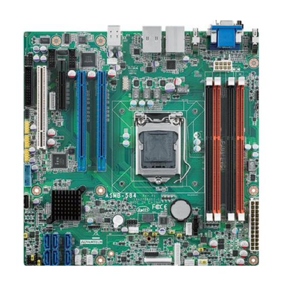
Page 18: Board Layout: Jumper And Connector Locations
Board Layout: Jumper and Connector Locations PCIEX16_SLOT7 VGA1 + LAN2_USB4 5 COM2 DV I1 AUDIO1 FPAUD1 LAN1_USB01 COM1 SYSFAN3 SPDIF_OUT1 PCI_SLOT4 ATX12V1 LPT1 LANLED1 PCIEX4_SLOT5 JPEG2 KBMS2 KBMS2 GPIO1 DIMMB1 PCIEX16_SLOT6 DIMMB0 USB10 11 DIMMA1 USB8 9 USB8 9 DIMMA0 BMC1 USB6 7 JCASE1... -
Page 19: Asmb-584 Block Diagram
ASMB-584 Block Diagram Block Diagram PCIe Gen 3.0 x8 One PCIe x16 slot (ECC) DDR3 1066/1333/1600 Channel A PCIe Gen3.0 x8 One PCIe x16 slot (ECC) DDR3 1066/1333/1600 Intel LGA 1150 Haswell WS Level Shifter Processors (ECC) DDR3 1066/1333/1600 Display Port Channel B (ECC) DDR3 1066/1333/1600 Display Port... -
Page 20: Jumper Settings
Jumper Settings This section provides instructions on how to configure your motherboard by setting the jumpers. It also includes the motherboard default settings and your options for each jumper. 1.8.1 How to set jumpers You can configure your motherboard to match the needs of your application by set- ting the jumpers. - Page 21 1.8.1.3 Watchdog timer output (JWDT1) The ASMB-584 contains a watchdog timer that will reset the CPU. This feature means the ASMB-584 will recover from a software failure or an EMI problem. The JWDT1 jumper settings control the outcome of what the computer will do in the event the watchdog timer is tripped.
-
Page 22: System Memory
1.8.1.5 CPU,SYSTEM fan PWM/DC mode selection(CPUFAN_SEL1, SYSFAN_SEL1) The ASMB-584 contains a jumper that can support PWM or DC mode, Normally this jumper should be set with pin 1-2 closed. If you want to change to DC mode, set CPUFAN_SEL1, SYSFAN_SEL1 to 2-3 closed for disable. Table 1.7: (CPUFAN_SEL1, SYSFAN_SEL1) Function Jumper Setting... -
Page 23: Cache Memory
1.11 Cache Memory The ASMB-584 supports a CPU with one of the following built-in full speed L3 caches: The built-in third-level cache in the processor yields much higher performance than conventional external cache memories. 8 MB for 4th Generation Intel Xeon E3-1275 V3 CPU ... - Page 24 ASMB-584 User Manual...
-
Page 25: Chapter 2 Connecting Peripherals
Chapter Connecting Peripherals... -
Page 26: Introduction
Introduction You can access most of the connectors from the top of the board as it is being installed in the chassis. If you have a number of cards installed, you may need to par- tially remove a card to make all the connections. Parallel Port (LPT1) LPT1 The parallel port is normally used to connect the motherboard to a printer. -
Page 27: Usb Ports (Lan1_Usb01,Lan2_Usb45,Usb23, Usb67, Usb89,Usb1011, Usb12)
USB Ports (LAN1_USB01,LAN2_USB45,USB23, USB67, USB89,USB1011, USB12) ASMB-584 provides up 13 USB ports. USB4~14 are USB 2.0 ports supporting trans- mission rates up to 480 Mbps, and USB0~3 are USB 3.0 ports supporting transmis- sion rate up to 5Gbps.These ports support Plug & Play and hot swapping for up to 127 external devices and are able to be disabled in BIOS menu. -
Page 28: Usb Power Switch
USB Power Switch Jumper USB Ports JUSB1 USB port 2,3,and 6~12 JUSB1 ASMB-584 allows user to set USB power between +5VSB and +5V. When the jumper is set as +5V, the board doesn't support S3/S4. Note! When USB power is switched to +5V, it can't be connected with pow- ered KVM. -
Page 29: Vga Connector (Vga1)
VGA Connector (VGA1) VGA+DVI1 The ASMB-584 includes a VGA interface that can drive conventional CRT displays. Pin assignments of VGA1 are detailed in Appendix B. Serial Ports (COM1, COM2) COM2 COM1 COM1&2 The ASMB-584 offers two serial ports (both are onboard pin-headers). Both ports can connect to a serial mouse, printer or communications network. -
Page 30: External Keyboard & Mouse (Kbms2)
External Keyboard & Mouse (KBMS2) KBMS2 There is also an extra onboard external keyboard and mouse connector on the moth- erboard. This gives system integrators greater flexibility in designing their systems. CPU Fan Connector (CPUFAN1) CPUFAN_SEL1 CPUFAN0 If a fan is used, this connector supports cooling fans that draw up to 500 mA (6 W). ASMB-584 User Manual... -
Page 31: System Fan Connector (Sysfan0, Sysfan1, Sysfan2 And Sysfan3)
System FAN Connector (SYSFAN0, SYSFAN1, SYSFAN2 and SYSFAN3) SYSFAN3 SYSFAN0 STYSFAN1 SYSFAN2 STYSFAN3 SYSFAN_SEL1 SYSFAN2 SYSFAN0 SYSFAN1 If a fan is used, this connector supports cooling fans that draw up to 1A (12W). 2.10 Front Panel Connectors (JFP1) There are several external switches and LEDs to monitor and control the ASMB-584. JFP1 PWRSW RESET... -
Page 32: Power Led (Jfp3)
2.10.1 Power LED (JFP3) JFP3 is a 5-pin connector for the power LED. Refer to Appendix B for detailed infor- mation on the pin assignments. If a PS/2 or ATX power supply is used, the system’s power LED status will be as indicated as follows. Table 2.1: PS/2 or ATX power supply LED status Power mode LED (PS/2 power) -
Page 33: 8-Pin Alarm Board Connector (Volt1)
2.11 8-pin Alarm Board Connector (VOLT1) VOLT1 VOLT1 connects to the alarm board of Advantech chassis. These alarm boards give warnings if a power supply or fan fails, if the chassis overheats. 2.12 Case Open Connector (JCASE1) JCASE1 JCASE1 is for chassis with a case open sensor. The buzzer on the motherboard sounds if the case is opened. -
Page 34: Front Panel Lan Indicator Connector (Lanled1)
2.13 Front Panel LAN Indicator Connector (LANLED1) Table 2.2: Front Panel LAN Indicator Connector Signal Signal LAN1_LED0_ACT LAN2_LED1_ACT VCC3_LAN1LED VCC3_LAN2LED LAN1_LED1_1000M LAN2_LED2_1000M LAN1_LED2_100M LAN2_LED0_100M VCC3 LANLED1 2.14 Serial ATA Interface (SATA0~5) 0 2 4 SATAIII 1 3 5 ASMB-584 features six high performance serial ATA III interfaces (up to 600 MB/s, blue connector). -
Page 35: Pci Slots (Pci_Slot4)
2.15 PCI Slots (PCI_SLOT4) PCI_SLOT4 The ASMB-584 provides one 32-bit / 33 MHz PCI slots. 2.16 PCIe x16 slots (x8 link) Expansion Slot (PCIEX16_SLOT6 and PCIEX16_SLOT7) PCIEX16_SLOT6 PCIEX16_SLOT7 The ASMB-584 provides two PCIe x16 slots (x8 link) for users to install add-on VGA cards when their applications require higher graphics performance than the CPU embedded graphics controller can provide, or high bandwidth demanded I/O card, such as frame grabber card, raid card and 10G LAN card. -
Page 36: Pcie X4 Expansion Slot (Pciex4_Slot5)
2.17 PCIe x4 Expansion Slot (PCIEX4_SLOT5) PCIEX4_SLOT5 2.18 Auxiliary 8-pin power connector (ATX12V1) For a fully configured system, we recommend that you use a power supply unit (PSU) that complies with ATX 12 V Specification 2.0 (or later version). Do not forget to con- nect the 8-pin EATX12 V power plug;... -
Page 37: Spi Flash Connector(Spi_Cn1)
SPI flash card pin header which can flash BIOS while ASMB-584 can not be power on and ensures platform integrity. SPI_CN1 2.20 Low Pin Count Connector (LPC1) LPC1 LPC connector on AIMB-584 is reserved for Advantech LPC modules Table 2.3: Advantech LPC Module List Signal PCA-TPM-00A1E TPM Module ASMB-584 User Manual... - Page 38 ASMB-584 User Manual...
-
Page 39: Bios Operation
Chapter BIOS Operation... -
Page 40: Introduction
Introduction AMIBIOS has been integrated into myriad motherboards for decades. In the past, people often referred to the AMIBIOS setup menu as BIOS, BIOS setup or CMOS setup. With the AMIBIOS Setup program, you can modify BIOS settings and control the special features of your computer. -
Page 41: Main Menu
3.2.1 Main Menu Press <Del> or <Esc> at bootup to enter AMI BIOS CMOS Setup Utility, the Main Menu will appear on the screen. Use arrow keys to select among the items and press <Enter> to accept or enter the sub-menu. Figure 3.2 Main setup screen The Main BIOS setup screen has two main frames. -
Page 42: Advanced Bios Features Setup
Advanced BIOS Features Setup Select the Advanced tab from the ASMB-584 setup screen to enter the Advanced BIOS setup screen. You can select any of the items in the left frame of the screen, such as CPU configuration, to go to the sub menu for that item. You can display an Advanced BIOS Setup option by highlighting it using the <Arrow>... -
Page 43: Pci Subsystem Settings
3.3.1 PCI Subsystem Settings Figure 3.4 PCI subsystem settings screen PCI Latency Timer Value in units of PCI clocks for PCI device latency timer register. VGA Palette Snoop This item is designed to solve problems caused by some non-standard VGA cards. Figure 3.5 PCI Express Setting ASMB-584 User Manual... - Page 44 Relaxed Ordering This item is to enable or disable PCIe device relaxed ordering. Extended Tag If this item is [Enabled], it allows device to use 8-bit tag field as a requester. No Snoop This item is to enable or disable PCIe device with “No Snoop” option. Maximum Payload This item is to set maximum payload of PCIe device or allow system BIOS to select the value.
-
Page 45: Acpi Settings
3.3.2 ACPI Settings Figure 3.6 ACPI Settings Enable Hibernation "Enable” or “disable" Hibernation. ACPI Sleep State Specifies the ACPI sleep state when the system enters suspend. Lock Legacy Resources "Enable" or "Disable" Lock Legacy Resources. S3 Video Repost This item is to enabled or disabled S3 video repost. ASMB-584 User Manual... -
Page 46: Trusted Computing
3.3.3 Trusted Computing Figure 3.7 TPM Settings Security Device Support “Enable” or “disable” TPM Support. You can purchase Advantech LPC TPM module to enable TPM function. P/N: PCA-TPM-00A1E ASMB-584 User Manual... -
Page 47: Cpu Configuration
3.3.4 CPU Configuration Figure 3.8 CPU Configuration Hyper-threading This item allows you to enable or disable Intel Hyper Threading technology. Active Processor Core Use this to select how many processor cores you want to activate when you are using a dual or quad core processor. Overclocking lock This item is to enable or disabled FLEX_RATIO(194) MSR. - Page 48 Adjacent Cache Line Prefetch The Adjacent Cache-Line Prefetch mechanism, like automatic hardware prefetch, operates without programmer intervention. When enabled through the BIOS, two 64- byte cache lines are fetched into a 128-byte sector, regardless of whether the addi- tional cache line has been requested or not. You may choose to enable or disable it. CPU AES This item is to enable or disable CPU advanced encryption standard instructions.
-
Page 49: Sata Configuration
3.3.5 SATA Configuration Figure 3.9 SATA Configuration SATA Controller(s) This item is to enable or disable SATA devices. SATA Mode Selection It's able to set as IDE, AHCI, or RAID when SATA Controllers are enable. SATA Controller Speed To set the maximum speed of SATA controllers, and there are three modes, Gen1, Gen2, and Gen3. -
Page 50: Pch-Fw Configuration
3.3.6 PCH-FW Configuration Figure 3.10 Intel ME FW Configuration Information This page is to show the Intel ME configuration ASMB-584 User Manual... -
Page 51: Amt Configuration
3.3.7 AMT Configuration Figure 3.11 AMT Configuration Intel AMT Enable or Disable Intel Active Management Technology BIOS Extension. BIOS Hotkey Pressed To enable or disable BIOS hotkey press. MEBx Selection Screen “Enable or Disable” MEBx selection screen. Hide Un-Configure ME Confirmation Hide un-configuration ME without password confirmation prompt. -
Page 52: Usb Configuration
3.3.8 USB Configuration Figure 3.12 USB Configuration Legacy USB Support This is for supporting USB devices under legacy OS such as DOS. When choosing "AUTO", the system will automatically detect if any USB device is plugged into the computer and enable USB legacy mode and disable USB legacy mode when no USB device is plugged in. -
Page 53: Smart Settings
3.3.9 SMART Settings Figure 3.13 SMART Setting SMART Self Test This item is to enable or disable SMART self test on all HDDs during post. ASMB-584 User Manual... -
Page 54: Super Io Configuration
3.3.10 Super IO Configuration Figure 3.14 Super IO Configuration Figure 3.15 Serial Port 1 Configuration ASMB-584 User Manual... - Page 55 Figure 3.16 Serial Port 2 Configuration Figure 3.17 Parallel Configuration Serial Port 1 Configuration Serial Port “Enable” or “disable” Serial Port 1. ASMB-584 User Manual...
-
Page 56: H/W Monitor
Change Settings Select optimal settings for serial port 1. Serial Port 2 Configuration Serial Port “Enable” or “disable” Serial Port 2. Change Settings Select optimal settings for serial port 2. Parallel Port “Enable” or “disable” Parallel Port. Change Settings Select optimal settings for parallel port. Device Mode To change the printer port mode. -
Page 57: Serial Port Console Redirection
ACPI Shutdown Temperature Use this to set the ACPI shutdown temperature threshold. When the system reaches the shutdown temperature, it will be automatically shut down by ACPI OS to protect the system from overheat damage. Smart Fan Enable or Disable CPU FAN and System FAN Mode to SMART FAN setting. 3.3.12 Serial Port Console Redirection Figure 3.19 Serial Port Console Redirection... - Page 58 Figure 3.20 Console Redirection Setting Terminal Type Select a terminal type to be used for console redirection. Options available: VT100/VT100+/ANSI /VT-UTF8. Bits per second Select the baud rate for console redirection. Options available: 9600/19200/57600/115200. Data Bits This item is to set data bits between [8] or [7]. Parity A parity bit can be sent with the data bits to detect some transmission errors.
- Page 59 Flow Control Flow control can prevent data loss from buffer overflow. When sending data, if the receiving buffers are full, a 'stop' signal can be sent to stop the data flow. Once the buffers are empty, a 'start' signal can be sent to re-start the flow. Hardware flow con- trol uses two wires to send start/stop signals.
-
Page 60: Chipset
Chipset Figure 3.21 Chipset 3.4.1 PCH-IO Configuration Figure 3.22 PCH-IO Configuration ASMB-584 User Manual... - Page 61 PCIE Wake To enable or disable PCIE to wake the system from S5. Deep Sx Power Policies Enable or disable Deep Sx feature. When Deep Sx is enabled, most power including 5VSB will be off during deep Sx for energy saving. SLP_S4 Assertion Width To select a minimum assertion width of the SLP_S4 signal.
- Page 62 Figure 3.24 PCI Express Slot 5 Configuration PCI Express Slot 5 To enable or disable PCI Express Slot 5. ASPM Support To set ASPM level for PCI Expres Slot 5. PCIe Speed To set PCIe speed for PCI Express Slot 5. Detect Non-Compliance Device Detect Non-compliance PCIE device.
- Page 63 Figure 3.25 USB Configuration USB Precondition Precondition work on USB host controller and root ports for faster enumeration. XHCI Mode Mode of operation of XHCI controller. USB Ports Pre-Port Disable Control Enable or disable USB port#0~13. ASMB-584 User Manual...
- Page 64 Figure 3.26 PCH Azalia Azalia Control detection of Azalia device. Figure 3.27 LAN Configuration LAN1 Controller Enable or disable onboard LAN1. ASMB-584 User Manual...
-
Page 65: System Agent (Sa) Configuration
LAN1 PXE OpROM Enable or disable boot options for legacy network devices. Wake on LAN1 Enable or disable integrated LAN to wake the system. LAN2 Controller Enable or disable onboard LAN2 LAN2 OpROM Enable or disable boot options for legacy network devices.Wake on LAN 3.4.2 System Agent (SA) Configuration Figure 3.28 System Agent (SA) Configuration... - Page 66 3.4.2.1 Graphics Configuration Figure 3.29 Graphics Configuration Primary Display To select which graphics device, IGFX/PEG/PCI should be primary display or select SG for switchable Gfx. Primary PEG Select which PEG port as a primary PEG when primary PEG is set as [PEG] or [PCIE].
- Page 67 3.4.2.2 NB PCIe Configuration Figure 3.30 NB PCIe Configuration PEG0~2 - Genx To configure PEG0~2 as Gen1,Gen2 or Gen3. Enable PEG To enable or disable the PEG. Detect Non-Compliance Device Detect Non-compliance PCIE device in PEG. Program PCIe ASPM after OpROM [Enable] : PCIe ASPM will be programmed after OpROM.
- Page 68 3.4.2.3 Memory Configuration Figure 3.31 Memory Configuration Memory Frequency Limiter To set the maximum memory frequency between [1067],[1333] and [1600]. ASMB-584 User Manual...
-
Page 69: Boot
Boot Figure 3.32 Boot Setup Prompt Timeout Use the <+> and <-> keys to adjust the number of seconds to wait for setup activa- tion key. Bootup NumLock State “On” or “Off” power-on state for the NumLock Quiet Boot If this option is set to Disabled, the BIOS displays normal POST messages. If Enabled, an OEM Logo is shown instead of POST messages. - Page 70 Figure 3.33 CSM16 Parameters GateA20 Active This items is useful When RT code is executed above 1MB. When this it's set as "UPON RQUEST", GA20 can be disabled using BIOS services. When it's set as "Always", it does not allow disabling GA20. Option ROM Messages “Force BIOS or Keep Current”...
-
Page 71: Security
Security Figure 3.34 Security Select Security Setup from the ASMB-584 Setup main BIOS setup menu. All Security Setup options, such as password protection, are described in this section. To access the sub menu for the following items, select the item and press <Enter>. ASMB-584 User Manual... -
Page 72: Save & Exit
Save & Exit Figure 3.35 Save & Exit Save changes and exit* When you have completed system configuration, select this option to save your changes, exit BIOS setup and boot into the OS so the new system configuration parameters can take effect. Discard changes and exit Select this option to quit setup without making any permanent changes to the system configuration. -
Page 73: Server Management
Launch EFI Shell from filesystem device This option allows you to attempt to launch the EFI Shell application (shellx64.efi) from one of the available file system devices. *When you do some critical changes, the system will still reboot even you choose "Save changes and exit". -
Page 74: Bmc Self Test Log
3.8.1 BMC Self Test Log Figure 3.37 BMC Self Test Log Erase Log Erase log options When Log is Full Select the action to be taken when log is full ASMB-584 User Manual... -
Page 75: System Event Log
3.8.2 System Event Log Figure 3.38 System Event Log SEL Components Enable/Disable all features of system event logging during boot Erase SEL Choose options for erasing SEL When SEL is Full Choose options for reactions to a full SEL Log EFI Status Codes Disable the logging of EFI status codes or log only error code or only progress code or both ASMB-584 User Manual... -
Page 76: Bmc Network Configuration
3.8.3 BMC Network Configuration Figure 3.39 BMC network configuration Configuration Address Source Select to configure LAN channel parameters statically or dynamically (by BMC /IPMI- 1000 module). Unspecified will not modify any BMC (IPMI-1000 module) network parameters during BIOS posting phase. ASMB-584 User Manual... -
Page 77: Chapter 4 Chipset Software Installation Utility
Chapter Chipset Software Installation Utility... -
Page 78: Beforeyou Begin
BeforeYou Begin To facilitate the installation of the enhanced display drivers and utility software, read the instructions in this chapter carefully. The drivers for the ASMB-584 are located on the software installation CD. Note! The files on the software installation CD are compressed. Do not attempt to install the drivers by copying the files manually. -
Page 79: Windows Os Driver Setup
Windows OS Driver Setup Insert the driver CD into your system's CD-ROM drive. You can see the driver folders items. Move the mouse cursor over the folder "01-Chipset". In CSI folder, you can click find an executable file to complete implementation of the driver. ASMB-584 User Manual... - Page 80 ASMB-584 User Manual...
-
Page 81: Chapter 5 Vga Setup
Chapter VGA Setup... -
Page 82: Introduction
Introduction The Intel® Core™ i processors are embedded with integrated graphics controller. You need to install the VGA driver to enable this function, which includes the follow- ing features: Optimized integrated graphic solution: With Intel® Graphics Flexible Display Interface, it supports versatile display options and 32-bit 3D graphics engine. Dual independent display, enhanced display modes for widescreen flat panels for extend, twin, and clone dual display mode, and optimized 3D support deliver an intensive and realistic visual experience. -
Page 83: Chapter 6 Lan Configuration
Chapter LAN Configuration... -
Page 84: Introduction
Introduction The ASMB-584 has two Gigabit Ethernet LANs via dedicated PCI Express x1 lanes (GbE LAN1: Intel I217LM; GbE LAN2: Intel I210-AT that offer bandwidth of up to 500 MB/sec, eliminating the bottleneck of network data flow and incorporating Gigabit Ethernet at 1000 Mbps. -
Page 85: Chapter 7 Intel Me
Chapter Intel ME... -
Page 86: Introduction
Introduction The Intel ME software components that need to be installed depend on the system's specific hardware and firmware features. The installer detects the system's capabili- ties and installs the relevant drivers and applications. Installation Insert the driver CD into your system's CD-ROM drive. Navigate to the "05. Other" folder and find folder "Intel ME"... -
Page 87: Intel Usb 3.0
Chapter Intel USB 3.0... -
Page 88: Introduction
Introduction ASMB-584 provides Intel® USB 3.0 and the data transfer rate of USB3.0(5Gbps) is 10 times to USB2.0(480Mbps). Installation Insert the driver CD into your system's CD-ROM drive. Navigate to the ""05. Other" folder and find "Intel USB3.0" folder to install the driver. Note! The Intel®... -
Page 89: Chapter 9 Sata Raid Setup
Chapter SATA RAID Setup... -
Page 90: Introduction
Introduction To support demanding disk I/O, Intel C226 chipset integrates six Serial ATA control- lers with software RAID 0, 1, 5, 10 capabilities. RAID 0 striping increases the storage performance and is designed to speed up data transfer rates for disk-intensive applications. RAID 1 mirroring protects valuable data that might be lost in the event of a hard drive failure. - Page 91 Appendix Programming the Watchdog Timer...
-
Page 92: Watchdog Timer Overview
The ASMB-584’s watchdog timer can be used to monitor system software operation and take corrective action if the software fails to function within the programmed period. This section describes the operation of the watchdog timer and how to pro- gram it. Watchdog timer overview The watchdog timer is built in to the super I/O controller NCT6776F. - Page 93 Unlock NCT6776F Select register of watchdog timer Enable the function of the watchdog timer Use the function of the watchdog timer Lock NCT6776F ASMB-584 User Manual...
-
Page 94: Example Programs
Table A.1: Watchdog timer registers Address of Read/ Value (2F) & description register (2E) Write Write this address to I/O address port 2E (hex) twice to unlock the 87 (hex) NCT6776F 07 (hex) write Write 08 (hex) to select register of watchdog timer. Write 01 (hex) to enable the function of the watchdog timer. - Page 95 Dec dx ; Set second as counting unit Mov al,0f5h Out dx,al Inc dx In al,dx And al,not 08h Out dx,al ;----------------------------------------------------------- Dec dx ; Set timeout interval as 10 seconds and start counting Mov al,0f6h Out dx,al Inc dx Mov al,10;...
- Page 96 Out dx,al ;----------------------------------------------------------- Dec dx ; Set timeout interval as 5 minutes and start counting Mov al,0f6h Out dx,al Inc dx Mov al,5; 5 minutes Out dx,al ;----------------------------------------------------------- Dec dx ; lock NCT6776F Mov al,0aah Out dx,al Enable watchdog timer to be reset by mouse ;----------------------------------------------------------- Mov dx,2eh ;...
- Page 97 ;----------------------------------------------------------- Mov dx,2eh ; unlock NCT6776F Mov al,87h Out dx,al Out dx,al ;----------------------------------------------------------- Mov al,07h ; Select registers of watchdog timer Out dx,al Inc dx Mov al,08h Out dx,al ;----------------------------------------------------------- Dec dx ; Enable the function of watchdog timer Mov al,30h Out dx,al Inc dx Mov al,01h...
- Page 98 Out dx,al Inc dx In al,dx Or al,01h Out dx,al ;----------------------------------------------------------- Dec dx ; Generate a time-out signal Mov al,0f7h Out dx,al ;Write 1 to bit 5 of F7 register Inc dx In al,dx Or al,20h Out dx,al ;----------------------------------------------------------- Dec dx ; lock NCT6776F Mov al,0aah Out dx,al ASMB-584 User Manual...
- Page 99 Appendix I/O Pin Assignments...
-
Page 100: Parallel Port (Lpt1)
Parallel Port (LPT1) Table B.1: Parallel Port (LPT1) Signal Signal STROBE* GND* AFD* IGND ERR* INIT* ACK* SLIN* BUSY SLCT USB2.0 Header (USB6~11) USB8_9 USB6_7 USB10_11 Table B.2: USB Header (USB6~11) Signal Signal USB_VCC5 USB_VCC5 USB_D- USB_D- USB_D+ USB_D+ ASMB-584 User Manual... -
Page 101: Usb3.0 Header (Usb2_3)
USB3.0 Header (USB2_3) Table B.3: USB 3.0 Header (USB2_3) Signal Signal +5V_USB2_3 USB3_RX_DN5 +5V_USB2_3 USB3_RX_DP5 USB3_RX_DN6 USB3_RX_DP6 USB3_TX_DN5 USB3_TX_DP5 USB3_TX_DN6 USB3_TX_DP6 USB2_N2 USB2_P2 USB2_N3 USB_OC USB2_P3 VGA Connector (VGA) Table B.4: VGA Connector (VGA) Signal Signal GREEN BLUE H-SYNC V-SYNC ASMB-584 User Manual... -
Page 102: Interface (Com12)
RS-232 Interface (COM12) COM1 COM2 Table B.5: RS-232 Interface (COM12) COM1/COM2 Signal SOUT External Keyboard and Mouse Connector (KBMS2) Table B.6: External Keyboard and Mouse Connector (KBMS2) Signal KB CLK KB DATA MS DATA MS CLK ASMB-584 User Manual... -
Page 103: System Fan Power Connector (Sysfan0~3)
System Fan Power Connector (SYSFAN0~3) Table B.7: Fan Power Connector Signal +12 V DETECT Power LED and Keyboard Lock (JFP3) Table B.8: Power LED and Keyboard Lock (JFP3) Function LED power + (3.3 V) LED power - #keylock Ground External Speaker Connector (JFP2) Table B.9: External Speaker Connector (JFP2) Function SPK_VCC... -
Page 104: Reset Connector (Jfp1)
B.10 Reset Connector (JFP1) Table B.10: Reset Connector (JFP1) Signal RESET B.11 HDD LED Connector (JFP2) Table B.11: HDD LED Connector (JFP2) Signal HDD_LED+ HDD_LED- B.12 ATX Soft Power Switch (JFP1) Table B.12: ATX Soft Power Switch (JFP1) Signal PWR-BTN ASMB-584 User Manual... -
Page 105: Usb/Lan Ports (Lan1_Usb01 And Lan2_Usb23)
B.13 USB/LAN ports (LAN1_USB01 and LAN2_USB23) LAN1_USB01 LAN2_USB23 Table B.13: USB Port Signal Signal VCC_DUAL Data0+ Data0- Table B.14: Giga LAN 10/100/1000 Mbps RJ-45 port Signal Signal MID0+ MID2+ MID0- MID2+ MID1+ MID3+ MID1- MID3+ ASMB-584 User Manual... -
Page 106: Front Panel Audio Connector (Fpaud1)
B.14 Front Panel Audio Connector (FPAUD1) Table B.15: Front Panel Audio Connector (FPAUD1) Signal MIC2_L AGND MIC2_R PRESENSE LIN2_R MIC_DEC FIO_JD LIN2_L LINEOUT2_DEC B.15 8-pin Alarm Board Connector (VOLT1) Table B.16: 8-pin Alarm Board Connector (VOLT1) Signal Signal 5VSB VCC3 -12V +12V ASMB-584 User Manual... -
Page 107: Case Open Connector (Jcase1)
B.16 Case Open Connector (JCASE1) Table B.17: Case Open Connector (JFP1) Signal CASEOP B.17 Front Panel LAN LED Connector (LAN_LED1) Table B.18: LAN LED Connector (LAN_LED1/2) Signal Signal LAN1_LED0_ACT LAN2_LED1_ACT VCC3_LAN1LED VCC3_LAN2LED LAN1_LED1_1000M LAN2_LED2_1000 LAN1_LED2_100M LAN2_LED0_100 VCC3 B.18 SPI_CN1: SPI flash card pin connector Table B.19: SPI_CN1:SPI fresh card pin connector Signal Signal... -
Page 108: System I/O Ports
B.19 System I/O Ports Table B.20: System I/O ports Addr. range (Hex) Device 000-01F DMA controller 020-021 Interrupt controller 1, programmable interrupt controller 022-03F Motherboard resources 040-043 System timer 060-060 Standard PS/2 Keyboard 064-064 Standard PS/2 Keyboard 070-077 Real-time clock, non-maskable interrupt (NMI) mask 081-091 DMA controller 0A0-0A1... -
Page 109: 1St Mb Memory Map
B.21 1st MB Memory Map Table B.22: 1st MB memory map Addr. range (Hex) Device E0000h - FFFFFh BIOS CC000h - DFFFFh Unused C0000h - CBFFFh VGA BIOS A0000h - BFFFFh Video Memory 00000h - 9FFFFh Base memory ASMB-584 User Manual... - Page 110 No part of this publication may be reproduced in any form or by any means, electronic, photocopying, recording or otherwise, without prior written permis- sion of the publisher. All brand and product names are trademarks or registered trademarks of their respective companies. © Advantech Co., Ltd. 2013...
Need help?
Do you have a question about the ASMB-584G2-00A2E and is the answer not in the manual?
Questions and answers