Table of Contents
Advertisement
Quick Links
Advertisement
Table of Contents

Related Manuals for Advantech ASMB-823I


Summary of Contents for Advantech ASMB-823I
- Page 1 User Manual ASMB-823I Dual LGA 2011-R3 Intel Xeon® E5-2600v3 ATX Server Board...
- Page 2 No part of this manual may be reproduced, copied, translated or transmitted in any form or by any means without the prior written permission of Advantech Co., Ltd. Information provided in this manual is intended to be accurate and reliable. How- ever, Advantech Co., Ltd.
- Page 3 Advantech has come to be known. Your satisfaction is our primary concern. Here is a guide to Advantech’s cus- tomer services.
-
Page 4: Declaration Of Conformity
Caution! There is a danger of a new battery exploding if it is incorrectly installed. Do not attempt to recharge, force open, or heat the battery. Replace the battery only with the same or equivalent type recommended by the man- ufacturer. Discard used batteries according to the manufacturer's instructions. ASMB-823I User Manual... - Page 5 LGA-2011 square CPU cooler for 4U 1960065684N001 Coolermaster chassis (160 W) Option PCA-AUDIO- Advantech Audio card Card HDA1E ASMB-RF348- Advantech ASMB-RF348 (2U riser card) 2*PCI-E x4 + 1*PCI-E x8 21A1E Riser Card ASMB-RF3X8- Advantech ASMB-RF3X8 (2U riser card) 1*PCI-Ex4 + 2*PCI-X 21A1E ASMB-823I User Manual...
- Page 6 It should be free of marks and scratches and in perfect working order upon receipt. When unpacking the ASMB-823I, check it for signs of shipping damage. (For example, damaged box, scratches, dents, etc.) If it is dam- aged or it fails to meet the specifications, notify our service department or local sales representative immediately.
-
Page 7: Table Of Contents
Clear CMOS Connector (JCMOS1, JME1) ..........29 2.17 PMBUS Connector (PMBUS1)..............30 2.18 Front Panel SMBUS Connector (SMBUS1) ..........31 2.19 IPMI Module Connector (BMC1) ............. 31 2.20 VOLT1 Connector (VOLT1) ..............32 2.21 GPIO Connector (GPIO1) ............... 33 Chapter AMI BIOS ..........35 ASMB-823I User Manual... - Page 8 External Keyboard Connector (KBMS2) ..........94 Table B.5: External Keyboard Connector (KBMS2)....94 System & CPU Fan Power Connector (SYSFAN0~2, CPUFAN0~1) ..94 Table B.6: Fan Power Connector (SYSFAN0~2, CPUFAN0~1) 94 Power LED (JFP3) .................. 94 ASMB-823I User Manual viii...
- Page 9 8-pin Alarm Board Connector (VOLT1)........... 98 Table B.15:8-pin Alarm Board Connector (VOLT1) ....98 B.16 Case Open Connector (JCASE1) ............98 Table B.16:Case Open Connector (JFP1) ........98 B.17 Front Panel LAN LED Connector (LANLED1)......... 98 Table B.17:LAN LED Connector (LANLED1)......98 ASMB-823I User Manual...
- Page 10 ASMB-823I User Manual...
-
Page 11: Chapter 1 Overview
Chapter Overview... -
Page 12: Introduction
High reliability and outstanding performance makes ASMB-823I the ideal plat- form for industrial server/networking applications. By using the Intel C612 chipset, the ASMB-823I offers a variety of features such as 9 onboard SATA III interfaces; it supports IRST (Intel Rapid Storage Technology) and provides RAID 0, 1, 10 and 5 (Windows only*);... -
Page 13: Specifications
System Power V standby) 2 x 8 pin SSI EPS 12 V power connector for CPU & Memory power CPU Power (12V) PCIe slot power 1 x 4pin 12 V power connector for PCIe slot 12 V input ASMB-823I User Manual... - Page 14 RoHS Compliant 6/6 Pb Free Operating Temperature: 0 to 40° C Non-operating Temperature: -40 to 85° C Environmental Spec. Operating Relative Humidity: 10% to 90% (non-condensing) Non-operating Relative Humidity: 10% to 95% (non-condens- ing) ASMB-823I User Manual...
-
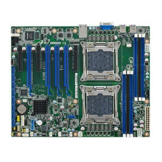
Page 15: Board Layout, Jumpers And Connectors
Board Layout, Jumpers and Connectors Connectors on the ASMB-823I are linked to external devices such as hard disk drives. In addition, ASMB-823I has a number of jumpers that are used to configure the system for specific applications. The tables below list the functions of each jumper and connector. Later sections in this chapter give instructions for setting jumpers. -
Page 16: Table 1.2: Onboard Lan Led Color Definition
Intel LGA2011 CPU1 socket CPUFAN0 CPU0 fan connector (4-pin) CPUFAN1 CPU1 fan connector (4-pin) DIMMA1 Channel A DIMM1 of CPU0 DIMMA2 Channel A DIMM2 of CPU0 DIMMB1 Channel B DIMM1 of CPU0 DIMMG1 Channel G DIMM1 of CPU1 ASMB-823I User Manual... -
Page 17: Table 1.5: Onboard Led
PCIE x16 slot of CPU0 SLOT7 PCIE x8 slot of CPU0 SLOT12V1 For PCIe slot 12V input only SMBUS1 SMBus header (For Advantech chassis usage) SPI_CN1 Connector for BIOS update tool SYS FAN0 System fan connector (4-pin) SYS FAN1 System fan connector (4-pin) -
Page 18: Block Diagram
PS/2 KB, MS Header Figure 1.3 Block Diagram System Memory ASMB-823I has six 288-pin memory slots for DDR4 1600/1866/2133 MHz memory modules with maximum capacity of 192 GB (Maximum 32 GB for each DIMM). ASMB-823I supports registered DIMMs memory module. - Page 19 To install DIMMs, first make sure the two handles of the DIMM socket are in the “open” position. i.e. The handles lean outward. Step 2 Slowly slide the DIMM module along the plastic guides on both ends of the socket, ASMB-823I User Manual...
- Page 20 Press the DIMM module right down into the socket, until you hear a click. This is when the two handles have automatically locked the memory module into the correct position of the DIMM socket. Step 4 Finished. ASMB-823I User Manual...
-
Page 21: Processor Installation
Processor Installation The ASMB-823I is designed for Intel E5-2600 v3 series Xeon processor. Step 1 Press the first lever and move it sideways slightly until it is released from the reten- tion tab. Step 2 Press the other lever and move it sideways slightly until it is also released from the retention tab. - Page 22 Lift the load plate. Step 4 Position the CPU over the socket ensuring that the triangle mark on the CPU lines up with the triangle mark on the motherboard. Triangle mark Step 5 Remove protective plastic cover. ASMB-823I User Manual...
- Page 23 Step 6 Close the load plate over the CPU. Step 7 Push down both levers and insert them under the retention tabs ensuring the edge of the load plate is fixed securely by both levers. Step 8 Finished. ASMB-823I User Manual...
- Page 24 ASMB-823I User Manual...
-
Page 25: Chapter 2 Connections
Chapter Connections... -
Page 26: Introduction
Mbps (USB 2.0) / 5Gbps (USB 3.0) and fuse protection are supported. The USB interface can be disabled in the system BIOS setup. The ASMB-823I is equipped with two high-performance 1000 Mbps Ethernet LANs. They are supported by all major network operating systems. The RJ-45 jacks on the rear plate provide convenient 1000Base-T operation. -
Page 27: Vga Connector (Vga1)
VGA Connector (VGA1) The ASMB-823I includes a VGA interface that can drive conventional CRT and LCD displays. VGA1 Serial Ports (COM2) The ASMB-823I offers one 2 x 5P pitch: 2.50mm serial port. (Onboard) COM2 COM2 ASMB-823I User Manual... -
Page 28: Ps2 Keyboard And Mouse Connectors (Kbms2)
CPU Fan Connector (CPU FAN0/FAN1) If a fan is used, this connector supports cooling fans that draw up to 1.5A (18W). CPUFAN1 CPUFAN0 Table 2.1: CPU FAN Pin Definition CPU FAN0 CPU FAN1 +12V +12V CPU0_TACH CPU1_TACH CPU0_PWM CPU1_PWM ASMB-823I User Manual... -
Page 29: System Fan Connector (Sys Fan0/Fan1/Fan2)
System Fan Connector (SYS FAN0/FAN1/FAN2) SYS SYS FAN2 FAN FAN0 Table 2.2: SYS FAN Pin Definition SYS FAN0 SYS FAN1 SYS FAN2 +12V +12V +12V FAN0_TACH FAN1_TACH FAN2_TACH FAN0_PWM FAN1_PWM FAN2_PWM ASMB-823I User Manual... -
Page 30: Front Panel Connector (Jfp1)
2.8.2 External Speaker (JFP2 pins 1, 4, 7, 10) JFP2 pins 1, 4, 7, 10 connect to an external speaker. The ASMB-823I provides an onboard buzzer as an alternative. To enable the buzzer, set pins 7-10 closed. ASMB-823I User Manual... -
Page 31: Hdd Led Connector (Jfp1 Pins 2 & 5)
Many computer cases offer the convenience of a reset button. 9 12 2.8.5 SNMP Connector (JFP1 Pins 8 & 11) SNMP connector could connect with “SAB-2000” remote control board to monitor ASMB-823I through the super IO chip. 8 11 (Data) (CLK) 2.8.6 Case Open (JCASE1) A Chassis Intrusion header is located at JCASE1 on the motherboard. -
Page 32: Sata Sgpio (Sgpio1 & 2)
SATA SGPIO (SGPIO1 & 2) SGPIO1 & 2 SCLOCK_PCH SLOAD_PCH SDATAOUT0_PCH SDATAOUT1_PCH ASMB-823I User Manual... -
Page 33: Front Panel Lan Indicator Connector (Lanled1)
2.10 Front Panel LAN Indicator Connector (LANLED1) LANLED1 LAN1_LED0_ACT LAN2_LED1_ACT VCC3_LAN1LED VCC3_LAN2LED LAN1_LED1_1000M LAN2_LED2_1000 LAN1_LED2_100M LAN2_LED0_100 VCC3 ASMB-823I User Manual... -
Page 34: Serial Ata Interface (Sata0-Sata4, Ssata0-Ssata3)
Serial ATA Interface (SATA0-SATA4, sSATA0- sSATA3) ASMB-823I features nine serial ATA III interfaces (up to 600 MB/s) which eases cabling to hard drives with thin and long cables. The sSATA1 located next to CPU0 allows SATA DOM (Serial ATA Disk on Module) installation for special application usage. -
Page 35: Pcie & Pci Expansion Slots
2.12 PCIe & PCI Expansion Slots The ASMB-823I provides several expansion slots. PCIEx8_SLOT7 PCIEx8_SLOT1 PCIEx8_SLOT2 PCIEx8_SLOT3 PCIEx8_SLOT4 PCIEx8_SLOT5 PCIEx8_SLOT6 Slot Length Link PCI-E Generation PCIe link provide from SLOT1 PCI-E x8 PCI-E x4 SLOT2 PCI-E x16 PCI-E x16 CPU1 SLOT3... -
Page 36: Auxiliary Power Connector (Atxpwr1/Atx12V1/Atx12V2)
Please use a power supply which is of SSI type; minimum output should be at least 700 W. ATXPWR1 & ATX12V1 & ATX12V2 sockets should be all con- nected with power supply, otherwise ASMB-823I will not boot up normally. ASMB-823I User Manual... -
Page 37: Hd Audio Interface Connector (Hdaud1)
2.14 HD Audio Interface Connector (HDAUD1) HDAUD1 HDAUD1 +5 V_AUD ACZ_SYNC ACZ_BITCLK ACZ_SDOUT ACZ_SDIN0 ACZ_SDIN1 ACZ_RST# +AC_12V ASMB-823I User Manual... -
Page 38: Lpc Connector (Lpc1) For Optional Tpm Module
2.15 LPC Connector (LPC1) for Optional TPM Module LPC1 CLK_33M_TPM LPC_AD1 PLTRST_LPC LPC_AD0 LPC_FRAME +3.3V LPC_AD3 LPC_AD2 SMB_SCL_LPC SERIRQ_PCH SMB_SDA_LPC +5V_AUX ASMB-823I User Manual... -
Page 39: Clear Cmos Connector (Jcmos1, Jme1)
2.16 Clear CMOS Connector (JCMOS1, JME1) Setting jumper from pin 1-2 to pin 2-3, then back to pin 1-2 to reset CMOS data. JCMOS1 JTHR_SEL1 & JME1 JCMOS1 JME1 SRTC_RST_PCH RTC_RST_PCH HDA_SDOUT_PCH 3.3V ASMB-823I User Manual... -
Page 40: Pmbus Connector (Pmbus1)
2.17 PMBUS Connector (PMBUS1) PMBUS1 SMB_SCL_PM SMB_SDA_PM SMB_ALT_PM +3.3V ASMB-823I User Manual... -
Page 41: Front Panel Smbus Connector (Smbus1)
2.18 Front Panel SMBUS Connector (SMBUS1) SMBUS1 +3.3V_AUX SMB_SCL_FRU SMB_SDA_FRU 2.19 IPMI Module Connector (BMC1) BMC1 IPMI1 This connector will only fit to ASMB-BMC-00A1E and only exist in ASMB-823I sku. ASMB-823I User Manual... -
Page 42: Volt1 Connector (Volt1)
2.20 VOLT1 Connector (VOLT1) VOLT1 VOLT1 connects to the alarm board on the Advantech chassis. These alarm boards give warnings if a power supply or fan fails, if the chassis overheats, or if the back- plane malfunctions. 5VSB +3.3V -12V... -
Page 43: Gpio Connector (Gpio1)
2.21 GPIO Connector (GPIO1) GPIO1 SIO_GPIO0 SIO_GPIO4 SIO_GPIO1 SIO_GPIO5 SIO_GPIO2 SIO_GPIO6 SIO_GPIO3 SIO_GPIO7 VCC_GPIO0 ASMB-823I User Manual... - Page 44 ASMB-823I User Manual...
-
Page 45: Chapter 3 Ami Bios
Chapter AMI BIOS... -
Page 46: Introduction
The Setup program uses a number of menus for making changes and turning the special features on or off. This chapter describes the basic navigation of the ASMB-823I setup screens. AMI's BIOS ROM has a built-in Setup program that allows users to modify the basic system configuration. -
Page 47: Bios Setup
System Date using the <Arrow> keys. Enter new values through the keyboard. Press the <Tab> key or the <Arrow> keys to move between fields. The date must be entered in MM/DD/YY format. The time must be entered in HH:MM:SS format. ASMB-823I User Manual... -
Page 48: Advanced Bios Features Setup
3.2.2 Advanced BIOS Features Setup Select the Advanced tab from the ASMB-823I setup screen to enter the Advanced BIOS setup screen. You can select any of the items in the left frame of the screen, such as CPU configuration, to go to the sub menu for that item. You can display an Advanced BIOS Setup option by highlighting it using the <Arrow>... - Page 49 3.2.2.1 ACPI Settings Enable Hibernation "Enable or disable" Hibernation. Lock Legacy Resources "Enable" or "Disable" Lock Legacy Resources. ASMB-823I User Manual...
- Page 50 3.2.2.2 NCT6776 Super IO Configuration Serial Port 1 Configuration – Serial Port "Enable" or "Disable" Serial Port 1. – Change Settings To select an optimal setting for serial port 1. ASMB-823I User Manual...
- Page 51 The default of CPU/System FAN is Smart FAN IV mode and the BIOS will auto- matically control the FAN speed by CPU temperature. When set to manual mode, fan duty setting can be changed; the range is from 30%~100%, default setting is 50%. ASMB-823I User Manual...
- Page 52 3.2.2.4 Serial Port Console Redirection Console Redirection To "Enable or disable" console redirection feature. ASMB-823I User Manual...
- Page 53 'stop' signal can be sent to stop the data flow. Once the buffers are empty, a 'start' signal can be sent to re-start the flow. Hardware flow control uses two wires to send start/stop signals. Options available: None/Hardware RTS/CTS. – Recorder Mode ASMB-823I User Manual...
- Page 54 It can be set as "9600", "19200", "57600", or "115200". "115200" is the default setting. – Flow Control Flow control can prevent data loss from buffer overflow. It can be set as "None", "Hardware RTS/CTS", or "Software Xon/Xoff". "None" is the default setting. ASMB-823I User Manual...
- Page 55 Value in units of PCI clocks for PCI device latency timer register. Above 4G Decoding Enables or disables 64-bit capability. Devices to be decoded in above 4G address space (Only if system supports 64-bit PCI decoding). Note! Some graphic or GPU cards need to enable 4G Decoding. ASMB-823I User Manual...
- Page 56 "UPON RQUEST", GA20 can be disabled using BIOS services. When it's set as "Always", it does not allow disabling GA20. Option ROM Messages "Force BIOS or Keep Current" to set the display mode for Option ROM ASMB-823I User Manual...
- Page 57 3.2.2.7 Trusted Computing Security Device Support Enables or disables BIOS support for security device. Purchase Advantech LPC TPM module to enable TPM function. P/N: PCATPM- 00A1E. ASMB-823I User Manual...
- Page 58 Selects the USB transfer time-out value. [1,5,10,20sec] Device Reset Time-out Selects the USB device reset time-out value. [10,20,30,40 sec] Device Power-up Delay This item appears only when Device power-up delay item is set to [manual]. ASMB-823I User Manual...
-
Page 59: Intelrcsetup
3.2.3 IntelRCSetup 3.2.3.1 Processor Configuration ASMB-823I User Manual... - Page 60 When enabled through the BIOS, two 64-byte cache lines are fetched into a 128-byte sector, regardless of whether the additional cache line has been requested or not. You may choose to enable or disable it. ASMB-823I User Manual...
- Page 61 This item is to enable or disable CPU advanced encryption standard instruc- tions. 3.2.3.2 Advanced Power Management Power Technology Power technology default is "Energy Efficient". User can set "EIST", "P-STATE", "C3", "C6", "Package C State limit" under "Custom" Mode. ASMB-823I User Manual...
- Page 62 ASMB-823I User Manual...
- Page 63 3.2.3.3 QPI Configuration ASMB-823I User Manual...
- Page 64 Select the QPI link speed as either the Fast mode or Slow Mode. QPI Frequency Select Allows for selecting the QPI Link frequency. QPI Link0p Enable/Disable QPI Link0p. QPI Link1 Enable/Disable QPI Link1. COD enable Enable/Disable Cluster on Die. Early Snoop Enable/Disable Early Snoop. ASMB-823I User Manual...
- Page 65 Early Snoop Configuration Enable Mode Disable Enable Auto Auto Early Snoop (ES) Auto Enable Disable Auto Disable Disable Home Snoop (HS) Auto Disable Enable Disable Cluster on Die (COD) Enable Auto Not Supported - Invalid Enable Enable Settings ASMB-823I User Manual...
- Page 66 3.2.3.4 Memory Configuration Data Scrabbling Enable/Disable Data Scrambling. NUMA Enable/Disable non uniform memory access (NUMA). Memory Technology Display memory topology with DIMM population information. ASMB-823I User Manual...
- Page 67 3.2.3.5 IIO Configuration CPU0/CPU1 PCIe Configuration PCIe port bifurcation control and select target link speed as Gen1, Gen2, Gen3. ASMB-823I User Manual...
- Page 68 ASMB-823I User Manual...
- Page 69 ASMB-823I User Manual...
- Page 70 ASMB-823I User Manual...
- Page 71 Force all links to L0s state; [Disable]: To disable ASPM. Extended Synch If this item is set to [Enable], allows generation of extended synchronization patterns. VGA Priority Determines priority between onboard and 1st off-board video device found. ASMB-823I User Manual...
- Page 72 XHCI Mode Mode of operation of XHCI controller. Azalia HD Audio Enable/Disable Azalia HD audio function. PCIe Slot 4 Configuration To enable or disable PCI Express Slot 4 and select target link speed as Gen1, Gen2. ASMB-823I User Manual...
- Page 73 PCH SATA and sSATA Configuration – SATA Controller(s) This item is to enable or disable SATA devices. – Configure SATA Mode Set as IDE, AHCI, or RAID when SATA Controllers are enabled. ASMB-823I User Manual...
- Page 74 LAN1 Controller Enable/Disable Intel I210 Controller support. – LAN1 PXE OpROM Enable/Disable Boot option for Intel I210 controller. – LAN2 Controller Enable/Disable Intel I210 Controller support. – LAN2 PXE OpROM Enable/Disable Boot option for Intel I210 controller. ASMB-823I User Manual...
- Page 75 3.2.3.7 Server ME Configuration This page shows the Server ME configuration ASMB-823I User Manual...
-
Page 76: Server Management
Disable the logging of EFI status codes or log only error code or only progress code or both. 3.2.4.2 BMC Self Test Log Erase Log Erase log options. When Log is Full Select the action to be taken when log is full. ASMB-823I User Manual... -
Page 77: Security
Note! With AC power & Battery. Short CMOS1 Jumper: Date/Time & Password: Keep Setting: reset to default AC power and CMOS battery are removed. Short CMOS1 Jumper: Date/Time: reset to default Password: Keep Setting: reset to default ASMB-823I User Manual... -
Page 78: Boot
Number of seconds to wait for setup activation key. 16 (0x10) means indefinite waiting. Bootup NumLock State Select the keyboard NumLock state. Quiet Boot Enable/Disable quiet boot option. Boot Option Priorities Sets the system boot priorities. ASMB-823I User Manual... -
Page 79: Save & Exit
Restore Defaults Restore/Load default values for all the setup options. Save as User Defaults Save the changes done so far as user defaults. Restore User Defaults Restore the user defaults to all the setup options. ASMB-823I User Manual... - Page 80 ASMB-823I User Manual...
-
Page 81: Chipset Software Installation Utility
Chapter Chipset Software Installation Utility... -
Page 82: Before Beginning
Before Beginning To facilitate the installation of the enhanced display drivers and utility software, read the instructions in this chapter carefully. The drivers for the ASMB-823I are located on the software installation CD. Before beginning, it is important to note that most display drivers need to have the relevant software application already installed on the system prior to installing the enhanced display drivers. -
Page 83: Windows 7 & 8/ Windows Server 2008 & 2012
Windows 7 & 8/ Windows server 2008 & 2012 Insert the driver CD into your system's CD-ROM drive. When the folder is dis- played, move the mouse cursor over the folder "01_Intel INF". Find the execut- able in this folder, click to install the driver. ASMB-823I User Manual... - Page 84 Click setup to execute the program. ASMB-823I User Manual...
-
Page 85: Vga Setup
Chapter VGA Setup... -
Page 86: Introduction
Insert the driver CD into your system's CD-ROM drive. When the folder is displayed, navigate to the "02_Graphic chip" folder and click the executable file to complete the installation of the drivers for OS that you need. ASMB-823I User Manual... - Page 87 Note! If ASMB-823I carries an additional graphics card for VGA output, please set this additional graphic card as "major output" under the "Display properties" of OS. Please use the driver file from "Windows WDDM" folder as first choice. XDDM and WDDM Driver Selection for Win7/Vista/2008/2008R2 –...
- Page 88 ASMB-823I User Manual...
-
Page 89: Lan Configuration & Usb 3.0
Chapter LAN Configuration & USB 3.0... -
Page 90: Lan Configuration
6.1.1 Introduction The ASMB-823I has two Gigabit Ethernet LAN connections via dedicated PCI Express x1 lanes: GbE LAN1 - Intel I210; GbE LAN2 - I210. They offer bandwidth of up to 500 MB/sec, eliminating the bottleneck of network data flow and incorporating Gigabit Ethernet at 1000 Mbps. -
Page 91: Usb 3.0
USB 3.0 6.2.1 Introduction ASMB-823I offers six USB 3.0 ports, four in rear side and two via onboard header. The USB 3.0 could provide the bandwidth up to 500MB/s to shorter the time for data transmission. 6.2.2 Windows Series Driver Setup Insert the driver CD into your system's CD-ROM drive. -
Page 92: Ahci & Sata Raid
1.Please visit the Intel download center for "Intel Rapid Storage Tech- nology enterprise for Microsoft Windows Operating System Software User's Guide" file download, The download address is: http://download.intel.com/support/motherboards/server/sb/ g40440_005_rste_swug_r1_5.pdf 2.For the hotfix file download, please visit: http://support.microsoft.com/kb/932755/en-us ASMB-823I User Manual... -
Page 93: Appendix A Programming The Watchdog Timer
Appendix Programming the Watchdog Timer... -
Page 94: Watchdog Timer Overview
The ASMB-823I’s watchdog timer can be used to monitor system software operation and take corrective action if the software fails to function within the programmed period. This section describes the operation of the watchdog timer and how to pro- gram it. - Page 95 Unlock NCT6776D Select watchdog timer register Enable the watchdog timer function Use the watchdog timer function Lock NCT6776D ASMB-823I User Manual...
-
Page 96: Example Programs
Mov al,07h ; Select registers of watchdog timer Out dx,al Inc dx in al,dx Or al,08h Out dx,al ;----------------------------------------------------------- Dec dx; Enable the function of watchdog timer Mov al,30h Out dx,al Inc dx Mov al,01h Out dx,al ;----------------------------------------------------------- ASMB-823I User Manual... - Page 97 Dec dx ; Enable the function of watchdog timer Mov al,30h Out dx,al Inc dx Mov al,01h Out dx,al ;----------------------------------------------------------- Dec dx ; Set minute as counting unit Mov al,0f5h Out dx, al Inc dx In al,dx Or al, 08h ASMB-823I User Manual...
- Page 98 Dec dx ; Enable watchdog timer to be reset by mouse Mov al,0f7h Out dx,al Inc dx In al,dx Or al,80h Out dx,al ;----------------------------------------------------------- Dec dx ; lock NCT6776D Mov al,0aah Out dx,al Enable watchdog timer to be reset by keyboard ASMB-823I User Manual...
- Page 99 Mov dx,2eh ; unlock NCT6776D Mov al,87h Out dx,al Out dx,al ;----------------------------------------------------------- Mov al,07h ; Select registers of watchdog timer Out dx,al Inc dx Mov al,08h Out dx,al ;----------------------------------------------------------- Dec dx ; Enable the function of watchdog timer Mov al,30h ASMB-823I User Manual...
- Page 100 Dec dx ; Generate a time-out signal Mov al,0f7h Out dx,al ;Write 1 to bit 5 of F7 register Inc dx In al,dx Or al,20h Out dx,al ;----------------------------------------------------------- Dec dx ; lock NCT6776D Mov al,0aah Out dx,al ASMB-823I User Manual...
-
Page 101: Appendix B I/O Pin Assignments
Appendix I/O Pin Assignments... -
Page 102: Usb2.0 Header (Usb67/89)
USB2.0 Header (USB67/89) USB67 Table B.1: USB Header (USB67) Signal Signal USB_VCC5 USB_VCC5 USB_D- USB_D- USB_D+ USB_D+ USB3.0 Header(USB2_3) Table B.2: USB Header (USB23,USB45,USB67,USB89) Signal Signal +5 V STDA_SSRX- STDA_SSRX+ STDA_SSRX- STDA_SSRX+ STDA_SSRX+ STDA_SSRX- STDA_SSRX+ STDA_SSRX- +5 V ASMB-823I User Manual... -
Page 103: Vga Connector (Vga1)
VGA Connector (VGA1) Table B.3: VGA Connector (VGA1) Signal Signal GREEN BLUE H-SYNC V-SYNC RS-232 Interface (COM2) Table B.4: RS-232 Interface (COM2) Signal ASMB-823I User Manual... -
Page 104: External Keyboard Connector (Kbms2)
MS DATA MS CLK System & CPU Fan Power Connector (SYSFAN0~2, CPUFAN0~1) Table B.6: Fan Power Connector (SYSFAN0~2, CPUFAN0~1) Signal +12 V FAN TACH Power LED (JFP3) Table B.7: Power LED (JFP1) Function LED power (3.3 V) Ground ASMB-823I User Manual... -
Page 105: External Speaker Connector (Jfp2)
1 4 7 10 Table B.8: External Speaker Connector (JFP2) Function SPK+ SPK- Reset Connector (JFP1) 9 12 Table B.9: Reset Connector (JFP1) Signal RESET B.10 HDD LED Connector (JFP1) Table B.10: HDD LED Connector (JFP1) Signal HDD_LED+ HDD_LED- ASMB-823I User Manual... -
Page 106: Atx Soft Power Switch (Jfp1)
B.11 ATX Soft Power Switch (JFP1) Table B.11: ATX Soft Power Switch (JFP1) Signal PWR-BTN B.12 Front panel SMBus Connector (SMBUS1) +3.3V_AUX SMB_SCL_FRU SMB_SDA_FRU ASMB-823I User Manual... -
Page 107: Usb/Lan Ports (Usb0_1, Usb4_5 And Lan1_2)
Table B.13: Giga LAN 10/100/1000 Base-T RJ-45 Port Signal Signal MID0+ MID2+ MID0- MID2+ MID1+ MID3+ MID1- MID3+ B.14 Audio Connector (HDAUD1) Table B.14: Front Panel Audio Connector (HDAUD1) Signal Signal ACZ_VCC ACZ_SYNC ACZ_BITCLK ACZ_SDOUT ACZ_SDIN0 ACZ_SDIN1 ACZ_RST ACZ_12V ASMB-823I User Manual... -
Page 108: 8-Pin Alarm Board Connector (Volt1)
B.16 Case Open Connector (JCASE1) Table B.16: Case Open Connector (JFP1) Signal CASEOP B.17 Front Panel LAN LED Connector (LANLED1) Table B.17: LAN LED Connector (LANLED1) Signal Signal LAN1/3_LED0_ACT LAN2/4_LED1_ACT VCC3_LAN1LED VCC3_LAN2LED LAN1/3_LED1_1000M LAN2/4_LED2_1000 LAN1/3_LED2_100M LAN2/4_LED0_100 VCC3 ASMB-823I User Manual... - Page 109 ASMB-823I User Manual...
- Page 110 No part of this publication may be reproduced in any form or by any means, electronic, photocopying, recording or otherwise, without prior written permis- sion of the publisher. All brand and product names are trademarks or registered trademarks of their respective companies. © Advantech Co., Ltd. 2014...
Need help?
Do you have a question about the ASMB-823I and is the answer not in the manual?
Questions and answers