Table of Contents
Advertisement
Quick Links
Advertisement
Table of Contents

Related Manuals for AirLive SNMP-GSH2404L


Summary of Contents for AirLive SNMP-GSH2404L
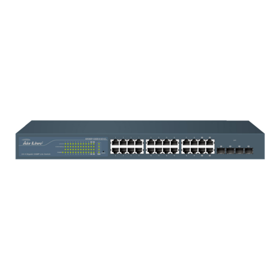
- Page 1 SNMP-GSH2404L 24+4 Gigabit SNMP Lite Switch User’s Manual...
- Page 2 OvisLink Corp. has made the best effort to ensure the accuracy of the information in this user’s guide. However, we are not liable for the inaccuracies or errors in this guide. Please use with caution. All information is subject to change without notice All Trademarks are properties of their respective holders. AirLive SNMP-GSH2404L User’s Manual...
- Page 3 Self-demolition on Product is strictly prohibited. Damage caused by self-demolition will be charged for repairing fees. Do not place product at outdoor or sandstorm. Before installation, please make sure input power supply and product specifications are compatible to each other. AirLive SNMP- GSH2404L User’s Manual...
-
Page 4: Table Of Contents
3.3 Management Interface ...............11 3.4 Introduction to Web Management............11 3.4.1 Getting into Web Management ..............12 4. Web Management in SNMP-GSH2404L..........14 4.1 Menu Structure of SNMP-GSH2404L ..........14 4.2 Configuration ..................15 4.2.1 System Configuration ................16 4.2.2 Port ......................20 4.2.3 VLAN Mode Configuration .................21 4.2.4 VLAN Group Configuration ................25... - Page 5 4.4 Maintenance ..................59 4.4.1 Warm Restart.....................59 4.4.2 Factory Default ..................60 4.4.3 Software Upgrade..................60 4.4.4 Configuration File Transfer ................61 4.4.5 Logout......................62 5. Troubleshooting..................64 5.1 Incorrect connections.................64 5.2 Diagnosing LED Indicators ..............65 5.3 Cabling....................65 6. Specifications...................66 7. Network Glossary ..................69 AirLive SNMP-GSH2404L User’s Manual...
-
Page 6: Introduction
You should read at least go through the first 2 chapters before attempting to install the device. Recommended Reading Chapter 1: This chapter explains the basic information for SNMP-GSH2404L. It is a must read. Chapter 2: This chapter is about hardware installation. You should read through the entire chapter. -
Page 7: Firmware Upgrade And Tech Support
WebUI using HTTP. Chapter 4: This chapter explains all of the management functions via Web management. Chapter 5: If any trouble in using SNMP-GSH2404L, you can refer to this chapter Chapter 6: This chapter shows technical specification of SNMP-GSH2404L. Chapter 7: Explanation on network technical terms from A to Z. Highly recommended for reference when you encounter an unfamiliar term. -
Page 8: Features
The trap event and alarm message can be transferred via e-mail Supports diagnostics to let administrator knowing the hardware status HTTP and TFTP for firmware upgrade, system log upload and configuration file import/export Supports remote boot the device through user interface and SNMP irLive SNMP-GSH2404L User’s Manual... -
Page 9: Installing The Snmp-Gsh2404L
For software configuration, please go to chapter 3 for more details. 2.2 Before You Start It is important to read through this section before you install the SNMP-GSH2404L. The maximum cabling distance is 100 meters. Do not create a network loop. -
Page 10: Optional Accessories
User Guide (CD-ROM) Quick Installation Guide Rack-mounted Kit Compare the contents of your SNMP-GSH2404L package with the standard checklist above. If any item is missing or damaged, please contact your local dealer for service. 2.4 Optional Accessories The SNMP-GSH2404L has the following optional accessories which you can purchase... -
Page 11: Knowing Your Snmp-Gsh2404L
Below are descriptions and diagrams of the product: 2.6 Hardware Installation Set the SNMP-GSH2404L on a sufficiently large flat space with a power outlet nearby. The surface where you put your SNMP-GSH2404L should be clean, smooth, level and sturdy. Make sure there is enough clearance around the SNMP-GSH2404L to allow attachment of cables, power cord and allow air circulation. -
Page 12: Rack-Mounted Installation
Perform the following steps to rack mount the SNMP-GSH2404L: Position one bracket to align with the holes on one side of the SNMP-GSH2404L and secure it with the smaller bracket screws. Then attach the remaining bracket to the other side of the SNMP-GSH2404L. -
Page 13: Power On
2.6.3 Power On Connect the power cord to the power socket on the rear panel of the SNMP-GSH2404L. The other side of power cord connects to the power outlet. The internal power supply of the SNMP-GSH2404L works with voltage range of AC in the 100-240VAC, frequency 50~60Hz. - Page 14 2. Installing the SNMP-GSH2404L Status Description Power Green Power On Power is not connected 10/100/1000BASE-T Port 1 to 24 LNK/ACT Green The port is connecting with the device. Blink The port is receiving or transmitting data. No device attached. 10/100/1000Mbps...
-
Page 15: Configuring The Snmp-Gsh2404L
3. Configuring SNMP-GSH2404L Configuring the SNMP-GSH2404L You can configure SNMP-GSH2404L through web browser (http). In this chapter, we will explain SNMP-GSH2404L’s Web-based management interfaces and how to get into it. Then, we will provide the introduction on Web Management and recommended initial settings. -
Page 16: Management Interface
The SNMP-GSH2404L can be configured using on the Web management interfaces. Web Management (HTTP): You can manage your SNMP-GSH2404L by simply typing its IP address in the web browser. Most functions of SNMP-GSH2404L can be accessed by web management inter face. We recommend using this interface for initial configurations. -
Page 17: Getting Into Web Management
Launch the Internet Explorer. Type http://192.168.1.1. Press “Enter”. The login screen appears. Key in the user name and password. The default password is “airlive”. Click “Enter” or ”Apply”, then the home screen of the Web-based management appears. AirLive SNMP-GSH2404L User’s Manual... - Page 18 3. Configuring SNMP-GSH2404L AirLive SNMP-GSH2404L User’s Manual...
-
Page 19: Web Management In Snmp-Gsh2404L
In this chapter, we will explain all settings in web management interface. Please be sure to read through Chapter 3’s “Introduction to Web Management” first. 4.1 Menu Structure of SNMP-GSH2404L The web management menu of SNMP-GSH2404L is divided into 3 parts: Top Bar, Side Menu Bar, and Main Screen. Top Bar... -
Page 20: Configuration
4. Web Management in SNMP-GSH2404L Top Bar: It shows the front panel of the switch. Linked ports will be displayed in green color, and linked-off ones will be in black. For the optional modules, the slots with no module will only show covered plates, the other slots with installed modules would present modules. -
Page 21: System Configuration
4. Web Management in SNMP-GSH2404L Configuration System Configuration Ports VLANs Aggregation LACP RSTP 802.1X IGMP Snooping Mirror Filter Rate Limit Storm Control SNMP 4.2.1 System Configuration System configuration is one of the most important functions. Without a proper setting, network administrator would not be able to manage the device. The switch supports manual IP address setting. - Page 22 4. Web Management in SNMP-GSH2404L Function name: System Configuration Function description: Show system description, firmware version, hardware version, MAC address, serial number, active IP address, active subnet mask, active gateway, DHCP server and Lease time left. Set device name, DHCP enable, fallback IP address, fallback subnet mask, fallback gateway, management VLAN, password and inactivity timeout.
- Page 23 4. Web Management in SNMP-GSH2404L Firmware Version: The firmware version of this switch. Hardware Version: The hardware version of this switch. MAC Address: It is the Ethernet MAC address of the management agent in this switch. Serial Number: The serial number is assigned by the manufacturer.
- Page 24 4. Web Management in SNMP-GSH2404L all networks, hence, subnet mask is introduced to solve this problem. Subnet mask uses some bits from host address and makes an IP address looked Network address, Subnet mask number and host address. It is shown in the following figure.
-
Page 25: Port
4. Web Management in SNMP-GSH2404L 4.2.2 Port Function name: Port Configuration Function description: Port Configuration is applied for the settings of the ports on the switch. By this function, you can set or reset the values for Mode and Flow Control. Others you could set the power saving mode for switch power consumption. -
Page 26: Vlan Mode Configuration
4. Web Management in SNMP-GSH2404L Parameter description: Enable Jumbo Frames: This function support jumbo frames of up to 9600 bytes, Just tick the check box ( ) to enable it. Default: disable Perfect Reach/Power Saving Mode: This function supports Power Saving and perfect Reach, Just select with the Full/... - Page 27 4. Web Management in SNMP-GSH2404L gain not only improved security and increased performance, but also save a lot of VLAN management effort. Function name: VLAN Mode Setting Function description: The VLAN Mode Selection function includes four modes: Port-based, Tag- based, Metro mode or Disable, you can choose one of them by pulling down list and pressing the <Downward>...
- Page 28 4. Web Management in SNMP-GSH2404L Double-tag mode belongs to the tag-based mode, however, it would treat all frames as the untagged ones, which means that tag with PVID will be added into all packets. Then, these packets will be forwarded as Tag-based VLAN.
- Page 29 4. Web Management in SNMP-GSH2404L Parameter description: Port 1-24: Port number. Ingress Filtering Enabled: Discard other VLAN group packets, only forward this port joined VLAN group packets. Packet Type: All: Forward all tagged and untagged packets. Tagged Only: Forward tagged packets only and discard untagged packets.
-
Page 30: Vlan Group Configuration
4. Web Management in SNMP-GSH2404L Valid range is 1~4094. It works only when Role is set to Hybrid. Pvid: This PVID range will be 1-4094. Before you set a number x as PVID, you have to create a Tag-based VLAN with VID x. For example, if port x receives... - Page 31 4. Web Management in SNMP-GSH2404L Parameter description: ID (Group ID): When you want to edit a VLAN group, you must select the Group ID field. Then, you will enter Tag Base VLAN Group Setting or Port Base VLAN Group Setting page, which depends on your VLAN mode selection.
-
Page 32: Aggregation
4. Web Management in SNMP-GSH2404L Delete Group: Just tick the check box ( ) beside the ID, then press the <Delete> button to delete the group. 4.2.5 Aggregation The Aggregation (Port Trunking) Configuration is used to configure the settings of Link Aggregation. -
Page 33: Lacp
4. Web Management in SNMP-GSH2404L Parameter description: Normal: Set up the ports that do not join any aggregation trunking group. Group 1~8: Group the ports you choose together. Up to 12 ports can be selected for each group. 4.2.6 LACP Smart Web Switch supports link aggregation IEEE802.3ad standard. - Page 34 4. Web Management in SNMP-GSH2404L Parameter description: Protocol Enabled: Just tick the check box ( ) to enable LACP protocol then press the <Apply> button to apply. Key Value: It’s key for an aggregation. This must be an integer value between 1 and 255 or auto select by switch.
-
Page 35: Rstp
4. Web Management in SNMP-GSH2404L 4.2.7 RSTP In switches, bridges and routers. The protocol allows a switch to communicate with other RSTP compliant switches, and to ensure only one path existing between two stations in your network environment. The switch allows you to create multiple STP configurations and assign ports to a specific tree. -
Page 36: 802.1X
4. Web Management in SNMP-GSH2404L Function description: Enable or disable RSTP protocol on the ports that are selected and set path cost. Parameter description: Protocol Enabled: Just tick the check box ( ) beside the port x to enable RSTP protocol, then press the <Apply>... - Page 37 4. Web Management in SNMP-GSH2404L Before the devices or end stations can access the network resources through the ports under 802.1x control, the devices or end stations connected to a controlled port send the authentication request to the authenticator, the authenticator pass the request to the authentication server to authenticate and verify, and the server tell the authenticator if the request get the grant of authorization for the ports.
- Page 38 4. Web Management in SNMP-GSH2404L Supplicant Authentication Authentication System System System Service Offered by Authentication Authenticator Authentication (Bridge Relay) Server Controlled Port Uncontrolled Port Supplicant Port Authorize MAC Enable In the below figure, this is the typical configuration, a single supplicant, an authenticator and an authentication server.
- Page 39 4. Web Management in SNMP-GSH2404L login based on 802.1x port access control management. The protocol used in the right side is EAPOL and the left side is EAP. At the initial stage, the supplicant A is unauthenticated and a port on switch acting as an authenticator is in unauthorized state.
- Page 40 4. Web Management in SNMP-GSH2404L Bridge Radius Server Access blocked EAPOL-Start EAPOL Radius Authenticator EAP-Request/Identity Radius-Access-Request EAP-Response/Identity Radius-Access-Challenge EAP-Request Radius-Access-Request EAP-Response (cred) Radius-Access-Accept EAP-Success EAP-Failure EAP-Logoff Access allowed The 802.1X “Enabled” is the type of authentication supported in the switch. In this mode, for the devices connected to this port, once a supplicant is authorized, the devices connected to this port can access the network resource through this port.
- Page 41 4. Web Management in SNMP-GSH2404L Function name: 802.1X Configuration Function description: This function is used to configure the global parameters for RADIUS authentication in 802.1x port security application. Parameter description: Mode: Enable or disable 802.1X function. RADIUS IP: RADIUS server IP address for authentication.
- Page 42 4. Web Management in SNMP-GSH2404L Re-authenticate for all ports in at once. Force Reinitialize: Force the subscriber has to reinitialize connected to the port. Force Reinitialize All: Force Reinitialize for all ports in at once. Statistics: Choose the port which you want to show of 802.1X statistics, the screen include Authenticator counters, backend Authenticator counters, dot1x MIB counters and Other statistics.
- Page 43 4. Web Management in SNMP-GSH2404L Function name: 802.1x Parameters Function description: In here, user can enable or disable Reauthentication function and specify how often a client has to re-enter his or her username and password to stay connected to the port.
-
Page 44: Igmp Snooping
4. Web Management in SNMP-GSH2404L 4.2.9 IGMP Snooping Function name: IGMP Snooping Configuration Function description: IGMP Snooping lets administrators configure a switch to constrain multicast traffic by listening to Internet Group Management Protocol (IGMP). After finishing the settings, please press <Apply> button to start up the function. -
Page 45: Mirror Configuration
4. Web Management in SNMP-GSH2404L 4.2.10 Mirror Configuration Function name: Mirror Configuration Function description: Mirror Configuration is provided to monitor the traffic in the network. This switch supports one-port mirror multi-ports. For example, we assume that Port A and Port B are Source Ports, and Port C is Mirror Port respectively, thus, the traffic passing through Port A and Port B will be copied to Port C for monitor purpose. -
Page 46: Qos Configuration
4. Web Management in SNMP-GSH2404L 4.2.11 QoS Configuration The switch offers powerful QoS function. This function supports VLAN-tagged priority that can make precedence of 8 priorities, and DSCP(Differentiated Services Code Point) on Layer 3 of network framework. Function name: QoS Configuration Function description: AirLive SNMP-GSH2404L User’s Manual... - Page 47 4. Web Management in SNMP-GSH2404L While setting QoS function, please select QoS Mode in drop-down menu at first. Then you can use 802.1p Priority and DSCP Priority functions. In this function, you can enable/disable QoS Mode and set Priority Control, such as: 802.1p and DSCP. The switch only supports Strict Priority.
- Page 48 4. Web Management in SNMP-GSH2404L Function name: DSCP QoS Mode Function description: In the late 1990s, the IETF redefined the meaning of the 8-bit SERVICE TYPE field to accommodate a set of differentiated services (DS). Under the differentiated services interpretation, the first six bits comprise a codepoint, which is sometimes abbreviated DSCP, and the last two bits are left unused.
-
Page 49: Filter
4. Web Management in SNMP-GSH2404L 4.2.12 Filter Function name: Filter Configuration Function description: This function lets administrators easily set management source IP addresses to the ports on the switch. After completing the settings, please press <Apply> button to make this function take effect. - Page 50 4. Web Management in SNMP-GSH2404L Parameter description: Source IP Filter: Mode: There are three types of mode in this drop-down menu. Default is disabled. Disabled: Allow all IP Address login to this switch and manage it. Static: Just allow the IP Address which set by administrator to login to this switch and manage it..
-
Page 51: Rate Limit
4. Web Management in SNMP-GSH2404L 4.2.13 Rate Limit Function name: Ingress and Egress Bandwidth Setting Function description: Ingress and Egress Bandwidth Setting function are used to set up the limit of Ingress or Egress bandwidth for each port. AirLive SNMP-GSH2404L User’s Manual... -
Page 52: Storm Control
4. Web Management in SNMP-GSH2404L Parameter description: Ingress: Set up the limit of Ingress bandwidth (Range: 128Kb, 512Kb, 1M, 10M and 32M) for the port you choose. Incoming traffic will be discarded if the rate exceeds the value you set up in Data Rate field. Pause frames are also generated if flow control is enabled. -
Page 53: Snmp
4. Web Management in SNMP-GSH2404L Parameter description: ICMP Rate: To enable the ICMP Storm capability. User can use drop-down menu to select number of frames. Default is No Limit. The setting range is 1k~1024k per second. Learn Frames Rate: To enable the Learn Frames Storm capability. User can use drop-down menu to select number of frames. - Page 54 4. Web Management in SNMP-GSH2404L This function is used to configure SNMP settings, community name, trap host and public traps as well as the throttle of SNMP. A SNMP manager must pass the authentication by identifying both community names, then it can access the MIB information of the target device.
-
Page 55: Monitor
4. Web Management in SNMP-GSH2404L Default community name for Get: public Default community name for Set: private Default community name for Trap: public System Event: The System Event trap enable here is used for the “Cold Boot” or “Warm Boot” of system Event. - Page 56 4. Web Management in SNMP-GSH2404L Parameter description: Rx Packets: The counting number of the packet received. RX Octets: Total received bytes. Rx High Priority Packets: Number of Rx packets classified as high priority. Rx Low Priority Packets: Number of Rx packets classified as low priority.
- Page 57 4. Web Management in SNMP-GSH2404L Total transmitted bytes. Tx High Priority Packets: Number of Tx packets classified as high priority. Tx Low Priority Packets: Number of Tx packets classified as low priority. Tx Broadcast: Show the counting number of the transmitted broadcast packet.
-
Page 58: Lacp Status
4. Web Management in SNMP-GSH2404L Number of 512 ~ 1023-byte frames in good and bad packets transmitted. Tx 1024-Bytes: Number of 1024-max_length-byte frames in good and bad packets transmitted. Rx CRC/Alignment: Number of Alignment errors and CRC error packets received. -
Page 59: Rstp Status
4. Web Management in SNMP-GSH2404L Parameter description: LACP Aggregation Overview: Show the group/port status. Default will set to red sign for port link down, user can check legend table below for all reference. LACP Port Status: Group/Port: Show the port number. - Page 60 4. Web Management in SNMP-GSH2404L Parameter description: RSTP VLAN Bridge Overview: VLAN Id: Show the VLAN Id. Bridge Id: Show this switch’s current bridge priority setting and bridge ID which stands for the MAC address of this switch. Hello Time: Show the current hello time of the root bridge.
-
Page 61: Igmp Status
4. Web Management in SNMP-GSH2404L 4.3.4 IGMP Status Function name: IGMP Status Function description: Display IGMP status. It shows VLAN ID for each multicast group. Parameter description: VLAN Id: Show VLAN Id for each multicast group. Querier: Show the group membership queries status. -
Page 62: Ping Status
4. Web Management in SNMP-GSH2404L for each group to which it belongs. It Calculate the number of times of IGMPV1 report. V2 Reports: When a host receives a group membership query, it identifies the groups associated with the query and determines to which groups it belongs. The host then sets a timer, with a value less than the Max Response Time field in the query, for each group to which it belongs. - Page 63 4. Web Management in SNMP-GSH2404L Parameter description: Ping Parameters: Target IP address: Set up a Target IP address to ping. Count: Use drop-down menu to set number of echo requests to send. Four type of number can choose, there are 1, 5, 10 and 20.
-
Page 64: Maintenance
4. Web Management in SNMP-GSH2404L Received replies: Show the received replies number of times. Request timeouts: Show the timeout of request. Average Response times (In ms): Show the average response time in milliseconds. 4.4 Maintenance There are five functions contained in the maintenance function. -
Page 65: Factory Default
4. Web Management in SNMP-GSH2404L panel of the switch. Press <Yes> button to confirm warm restart function and it will take around thirty (30) seconds to complete the system boot. 4.4.2 Factory Default Function name: Factory Default Function description: Factory Default provides the function to retrieve default settings and replace current configuration. -
Page 66: Configuration File Transfer
4. Web Management in SNMP-GSH2404L You can just click Browse button to retrieve the file you want in your system to upgrade your switch. Once clicking “Upgrade” button, the windows will show upgrading progress as below figure After a while, window will tell user that “Software Successfully loaded” and will ask you if you want to activate new software. -
Page 67: Logout
4. Web Management in SNMP-GSH2404L You can backup your switch’s configuration file into your computer folder in case accident happens. In addition, uploading backup configuration file into a new or a crashed switch can save much time and avoid mistakes. - Page 68 4. Web Management in SNMP-GSH2404L Auto/Manual Logout: If no action and no key is stroke as well in any function screen more than the minutes you set up in Auto Logout Timer, the switch will have you logout automatically. Or press the <Logout>...
-
Page 69: Troubleshooting
Between any two ends nodes, there should be only one active cabling path at any time. Data path loops will cause broadcast storms that will severely impact your network performance. AirLive SNMP-GSH2404L User’s Manual... -
Page 70: Diagnosing Led Indicators
5. Troubleshooting 5.2 Diagnosing LED Indicators The SNMP-GSH2404L can be easily monitored through panel indicators to assist in identifying problems, which describes common problems you may encounter and where you can find possible solutions. Please refer to Chapter 2.7 for detailed information. -
Page 71: Specifications
6. Specifications Specifications This section provides the specifications of SNMP-GSH2404L, and the following table lists these specifications. Standard IEEE802.3 10BASE-T IEEE802.3u 100BASE-TX IEEE802.3z Gigabit SX/LX IEEE802.3ab Gigabit 1000TX IEEE802.3x Flow Control and Back pressure IEEE802.3ad Port trunk with LACP IEEE802.1d Spanning tree protocol IEEE802.1p Class of service... - Page 72 Supports two scheduling, WRR and Strict Supports IGMP snooping Supports Port Mirroring Supports Unknown Unicast / Multicast / Broadcast Storm Control Supports ingress and egress per port bandwidth control with 1Mbps increment Supports 802.1x access control for port-based AirLive SNMP-GSH2404L User’s Manual...
- Page 73 Operating: 0 to 40°C Storage: -10 to 70°C Operating: 10% ~ 90% Humidity Storage: 5% ~ 90% Power 100~240VAC 50/60Hz (maximum) Power consumption 20Watts Produce Weight (g) 2400 g Dimensions 442 x 170 x 44 mm AirLive SNMP-GSH2404L User’s Manual...
-
Page 74: Network Glossary
This standard allows transmission distance of 5km or more using single mode fiber. The 1000Base-LX cannot run in 100Mbps mode. 1000Base-T Also known 802.3ab standard. The IEEE standard defines how to transmit Gigabit data AirLive SNMP-GSH2404L User’s Manual... - Page 75 Dynamic Hosting Configuration Protocol. A protocol that enables a server to dynamically assign IP addresses. When DHCP is used, whenever a computer logs onto the network, it automatically gets an IP address assigned by DHCP server. A DHCP server can either be a AirLive SNMP-GSH2404L User’s Manual...
- Page 76 Link Aggregation Control Protocol. It is protocol defines how to combine the several Ethernet ports into one high-bandwidth port to increase the transmission speed. It is also known as port trunking. Both devices must set the trunking feature to work. AirLive SNMP-GSH2404L User’s Manual...
- Page 77 (NMS). Managed devices are network devices that contain SNMP agents. SNMP agents are programs that reside SNMP capable device’s firmware to provide SNMP configuration service. The NMS typically is PC-based software that can monitor and control managed devices remotely. AirLive SNMP-GSH2404L User’s Manual...
- Page 78 Trivial File transfer Protocol. A file transfer protocol, with the functionality of a very basic form of FTP. It is used to transfer small amounts of data between hosts on a network, such as Switch firmware. AirLive SNMP-GSH2404L User’s Manual...
Need help?
Do you have a question about the SNMP-GSH2404L and is the answer not in the manual?
Questions and answers