Table of Contents
Advertisement
Quick Links
Advertisement
Table of Contents

Related Manuals for AirLive ETHER-FSH2422W


Summary of Contents for AirLive ETHER-FSH2422W
- Page 1 Ether-FSH2422W 24+2G Web Management Switch User’s Manual...
-
Page 2: Declaration Of Conformity
5F., NO.6, Lane 130, Min-Chuan Rd., Hsin-Tien City, Taipei County, Taiwan Declare that the product 24+2 ports Mixed Gigabit Combo Web Management Switch AirLive Ether-FSH2422W is in conformity with In accordance with 89/336 EEC-EMC Directive and 1999/5 EC-R & TTE Directive Clause... - Page 3 1999/5/CE. muiden ehtojen mukainen Ar šo OvisLink Corp. deklarē, ka AirLive Ether- Hér með lýsir OvisLink Corp yfir því að AirLive Ether- Latviski [Latvian] FSH2422W atbilst Direktīvas 1999/5/EK Íslenska [Icelandic] FSH2422W er í...
-
Page 4: Fcc Warning
Consult the dealer or an experienced radio/TV technician for help. CE Mark Warning This is a Class-A product. In a domestic environment this product may cause radio interference in which case the user may be required to take adequate measures. AirLive Ether-FSH2422W User’s Manual... -
Page 5: Table Of Contents
TABLE OF CONTENT CHAPTER 1: INTRODUCTION ............. 1 1-1 Features ..................1 1-2 Package Contents ................. 2 CHAPTER 2: HARDWARE DESCRIPTION .......... 3 2-1 Physical Dimensions ..............3 2-2 Front Panel ................... 3 2-3 LED Indicators ................4 2-3-1 Gigabit port LED Indicator ............5 2-4 Rear Panel .................. - Page 6 5-2 Diagnosing LED Indicators ............44 CHAPTER 6: TECHNICAL SPECIFICATION ........45 APPENDIX ................... 47 10 /100BASE-TX Pin outs ..............47 10/100Base-TX Cable Schematic ............. 47 10/100/1000Base-TX Pin outs ............48 10/100/1000Base-TX Cable Schematic ..........49 AirLive Ether-FSH2422W User’s Manual...
-
Page 7: Chapter 1: Introduction
Chapter 1: Introduction The Ether-FSH2422W is a multi-port Switch that can be used to build high-performance switched workgroup networks. This switch is a store-and-forward device that offers low latency for high-speed networking. The switch is targeted at workgroup, department or backbone computing environment. -
Page 8: Package Contents
24 10/100TX + 2 10/100/1000T/Mini-GBIC Combo Web Smart Switch Mounting Plate Power Cord Four Rubber Pads Compare the contents of the Ether-FSH2422W package with the standard checklist above. If any item is missing or damaged, please contact the local dealer for exchanging. AirLive Ether-FSH2422W User’s Manual... -
Page 9: Chapter 2: Hardware Description
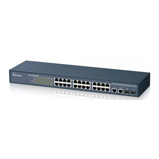
Chapter 2: Hardware Description This section mainly describes the hardware of the Ether-FSH2422W and gives a physical and functional overview on the certain switch. 2-1 Physical Dimensions The Ether-FSH2422W physical dimensions is 440mm x 120mm x 44mm (W x D x H). -
Page 10: Led Indicators
The port works in 10/100 Half-duplex mode seconds and on alternatively) No device attached Amber The port works at speed of 100Mbps Speed Blinks The port works at speed of 10Mbps The Description of LED Indicators AirLive Ether-FSH2422W User’s Manual... -
Page 11: Gigabit Port Led Indicator
The Descriptions of Gigabit port LED Indicators 2-4 Rear Panel The 3-pronged power plug is located at the rear panel of the Ether-FSH2422W shown below. The switch will work with AC in the voltage range between 100 and 240V and Frequency of 50-60Hz. -
Page 12: Desktop Installation
2-6 Rack-mounted Installation The Ether-FSH2422W comes with a rack-mounted kit and can be mounted in an EIA standard size, 19-inch Rack. The switch can be placed in a wiring closet with other equipment. Perform the following steps to rack mount the switch: Position one bracket to align with the holes on one side of the switch and secure it with the smaller bracket screws. -
Page 13: Chapter 3: Network Application
This section provides you a few samples of network topology in which the switch is used. In general, Ether-FSH2422W is designed as a segment switch which with its large address table (4k MAC address) and high performance, it is ideal for interconnecting networking segments. -
Page 14: Segment Uplink
In the illustration below, two Ethernet switches (with PCs, print server, and local server attached) are connected via 1000-FX or 10/100/1000Base-TX cable. All the devices in this network can communicate with each other through the switches. Connecting servers to the switch allows other users to access the data on server. AirLive Ether-FSH2422W User’s Manual... -
Page 15: Chapter 4: Web-Based Management
The Web management only allows one person to log in at the same time. With the first user logging, the system will force him to be logged out when the second user tries to log in the system. AirLive Ether-FSH2422W User’s Manual... -
Page 16: User Login
4-2 User Login Launch the Internet Explorer. Key in ‘http://192.168.10.1’ and the IP address assigned to the Ether-FSH2422W. Then, press “Enter”. The login screen appears. Key in ID & Password. The default login ID and password are “airlive”. Click “OK”, then the main page of the Web-based management appears. -
Page 17: Administrator
4-4-1 Authentication Configuration Change web management login user name and password for the management security issue. Username: Type in the new user name (The default value is ‘airlive’). Password: Type in the new password (The default value is ‘airlive’). Confirm password: Re-type the new password. -
Page 18: System Ip Configuration
Subnet Mask: Assign the subnet mask to the IP address. If DHCP function is enabled, and then the user does not need to assign the subnet mask. Gateway: Assign the network gateway for the Ether-FSH2422W. The default gateway is empty. -
Page 19: System Status
Comment: Users can fill in up to 12 characters in this field. Click the Update button to save the comments. System Version: Displays the switch’s firmware version Kernel Version: Displays the kernel version Apply And than, click button. System Status interface AirLive Ether-FSH2422W User’s Manual... -
Page 20: Default Switch Setting And Reboot
Reset switch to default configuration. Click to reset all configurations to the default value. Factory Default interface When you see the information as below, close the web window and launch again after a while. Reboot in progress AirLive Ether-FSH2422W User’s Manual... -
Page 21: Port Management
Select Port No.: Tick the check boxes beside the port numbers being set. Click Update to have the configuration take effect. Current Status: Displays current port status. Setting Status: Displays current. Update Click to make the configuration effective. AirLive Ether-FSH2422W User’s Manual... - Page 22 Port Configuration interface AirLive Ether-FSH2422W User’s Manual...
-
Page 23: Port Mirroring
Source Port: The ports that the user wants to monitor. All monitored port traffic will be copied to mirroring (destination) port. Users can select multiple source ports by ticking the check boxes beneath the port number label to be monitored. And then, click Update to have the configuration take effect. AirLive Ether-FSH2422W User’s Manual... -
Page 24: Bandwidth Control
Speed Base: Pull down the selection menu item to choose the speed base in low or high mode. As the picture shows, Port No: Pull down the selection menu to choose a port to be configured. AirLive Ether-FSH2422W User’s Manual... - Page 25 Tx Rate: Pull down the selection menu to choose the transmitting rate. When Speed Base is set as Low, the transmitting rate for all the ports is in the range between 32K bytes and 8M bytes. When Speed Base is set as High, the transmitting rate for port 1 ~ 24 is in the range between 256K bytes and 64M bytes;...
-
Page 26: Broadcast Storm Control
Enable Port: Having ticked the boxes, the port will stop transmitting or receiving data when their sending byte counts or receiving byte counts reach the defined threshold. Click Update to have the configuration take effect. AirLive Ether-FSH2422W User’s Manual... -
Page 27: Vlan Setting
Dest PORT: The label of each port. Select: Tick the check boxes to have the ports being the members of the VLAN. Click Update to have the configuration take effect. VLAN MEMBER: Displays the member ports for all the ports. AirLive Ether-FSH2422W User’s Manual... - Page 28 VLAN Member Setting (Port Based) interface AirLive Ether-FSH2422W User’s Manual...
-
Page 29: Vlan Mode
UplinkPort/Tag Mode: There are four radio buttons—Uplink, AddTag, don’t care, and RemoveTag—for selecting. Uplink: In normal operation, if the destination and source are located in different VLANs, the packets will be dropped. Having ticked the radio button, the port is configured as an AirLive Ether-FSH2422W User’s Manual... - Page 30 AddTag: A tag port always adds a tag to a forwarded packet with VID selected by PVID. Don’t care: If the NIC of a PC doesn’t support 802.1Q VLAN tagging, select this radio button to ignore the packets tagged. RemoveTag: An un-tagged port always removes a tag from a forwarded packet. AirLive Ether-FSH2422W User’s Manual...
-
Page 31: Vlan Pvid Index Setting
When an un-tagged packet is received, the switch uses the default PVID for the source port as index to the VID of the packet. The switch forwards the packet in the same way as mentioned above. Port: Labeled as the port number. PVID Index (1 ~ 32): Define the index of PVID. AirLive Ether-FSH2422W User’s Manual... - Page 32 VLAN PVID Index Setting interface AirLive Ether-FSH2422W User’s Manual...
-
Page 33: Per Port Counter
Collision Count & Transmit Packet: Displays the counts of collision occurred and the counts of transmitted packets. Drop Packet & Receive Packet: Displays the counts of dropped and received packets. CRC error Packet & Receive Packet: Displays the counts of CRC error occurred and received packets. AirLive Ether-FSH2422W User’s Manual... - Page 34 Per Port Counter interface AirLive Ether-FSH2422W User’s Manual...
-
Page 35: Qos Setting
(CoS) differentiates high-priority traffic from lower-priority traffic. Tags may be added to the packets to identify such classes, but they do not guarantee delivery as do quality of service (QoS) functions, which are implemented in the network devices. AirLive Ether-FSH2422W User’s Manual... -
Page 36: Priority Mode
Select the priority mode by click the radio button beside the mode name and click Update to have the configuration take effect. Priority Mode interface AirLive Ether-FSH2422W User’s Manual... -
Page 37: Class Of Service Configuration
Port Base: Tick this check box to apply the priority rule to the packets passing through the ticked ports. VLAN Tag: Tick this check box to apply the priority rule to the packets passing the ticked ports by checking the 3-bit field within the frame header. AirLive Ether-FSH2422W User’s Manual... - Page 38 Class of Service Configuration interface AirLive Ether-FSH2422W User’s Manual...
-
Page 39: Security Filter
MAC addresses bound with the port or modify the MAC addresses. Select Port: Pull down the selection menu bar to choose a port number to be set. Binding: Enable or disable the binding function. Click Update to have the configuration take effect. MAC Address Filter interface AirLive Ether-FSH2422W User’s Manual... -
Page 40: Trunk
Trunk 2: There are two ports—port 25 and port 26—can be involved in trunk group 2. Tick at least two check boxes and select the trunk type to configure Trunk 2. Click Update to have the configuration take effect. AirLive Ether-FSH2422W User’s Manual... - Page 41 Trunk Configuration interface...
-
Page 42: Aggregation Information
4-10-2 Aggregation Information Having set up the Trunk Configuration page in static mode, you will see the static trunk group information in here. Aggregation Information interface AirLive Ether-FSH2422W User’s Manual... -
Page 43: Configuration Backup/Recovery
Then the user has to fill in the password (login password) and click the Update button to start system configuration recovery process. Configuration Backup/Recovery interface AirLive Ether-FSH2422W User’s Manual... -
Page 44: Firmware Update
First, if you decide to update firmware via the web interface, just click the browser button to locate the firmware file. Having located the target firmware file, please click the Update button to start updating firmware. AirLive Ether-FSH2422W User’s Manual... - Page 45 Updating Firmware to the flash interface After a while, the message shows as below to indicate the user that the update process is complete. Update Complete message on web As for TFTP firmware update, users can get into the command prompt window to proceed. The command prompt window can be opened by entering "cmd"...
- Page 46 The system will erase the flash at first and then update the new firmware during the update process. If the update process is not finished, the web page of Firmware Update will always be displayed when the switch powers on. AirLive Ether-FSH2422W User’s Manual...
-
Page 47: Reboot
4-13 Reboot Click Reboot to restart the switch. Reboot interface AirLive Ether-FSH2422W User’s Manual... -
Page 48: Logout
Having clicked on Logout item in the tree menu, the system will ask the user to make sure to log out by clicking the Accept button or clicking the Back button to return to the previous web page. Logout Confirmation AirLive Ether-FSH2422W User’s Manual... -
Page 49: Chapter 5: Troubleshooting
Chapter 5: Troubleshooting This section is intended to help the user solve the most common problems on the Ether-FSH2422W. 5-1 Incorrect connections The switch port can auto-detect straight or crossover cable when the user links switch with other Ethernet device. The RJ-45 connector should use correct UTP or STP cable. 10/100Mbps ports use 2 pairs twisted cable and Gigabit 1000T ports use 4 pairs twisted cable. -
Page 50: Diagnosing Led Indicators
100Mbps connections. Also be sure that the length of any twisted-pair connection does not exceed 100 meters (328 feet). Gigabit port should use Cat-5 or cat-5e cable for 1000Mbps connections. The length does not exceed 100 meters. AirLive Ether-FSH2422W User’s Manual... -
Page 51: Chapter 6: Technical Specification
Chapter 6: Technical Specification This section provides the specifications of Ether-FSH2422W. IEEE802.3 10BASE-T IEEE802.3u 100BASE-TX IEEE802.3ab 1000BASE-T Standard IEEE802.3z Gigabit fiber IEEE802.3x Flow control and Back pressure IEEE802.3ad Port Trunk IEEE802.1p Class of Service System power (Green) 10/100TX Port: LED Indicators... - Page 52 15.4Watts (Maximum) Power Consumption Operating Temp. C ~ 45 Operating Humidity 10% ~ 90% (Non-condensing) Storage Temp. C ~ 70 Dimensions 440mm x 120mm x 44mm (W x D x H) FCC Class A Safety CE/EN60950-1 AirLive Ether-FSH2422W User’s Manual...
-
Page 53: Appendix
Appendix 10 /100BASE-TX Pin outs With10/100BASE-TX cable, pins 1 and 2 are used for transmitting data, and pins 3 and 6 for receiving data. RJ-45 Pin Assignments Pin Number Assignment [NOTE] “+” and “-” signs represent the polarity of the wires that make up each wire pair. The table below shows the 10 / 100BASE-TX MDI and MDI-X port pin outs. -
Page 54: 10/100/1000Base-Tx Pin Outs
Straight-through cable schematic Cross over cable schematic 10/100/1000Base-TX Pin outs The following figure shows the 10/100/1000 Ethernet RJ-45 pin outs. -
Page 55: 10/100/1000Base-Tx Cable Schematic
10/100/1000Base-TX Cable Schematic Straight through cables schematic Cross over cables schematic...
Need help?
Do you have a question about the ETHER-FSH2422W and is the answer not in the manual?
Questions and answers