Table of Contents
Advertisement
Advertisement
Table of Contents

Subscribe to Our Youtube Channel
Related Manuals for AirLive ETHER-GSH16TW


Summary of Contents for AirLive ETHER-GSH16TW
- Page 1 Ether-GSH16TW 16-Port Gigabit Ethernet Web Management Switch User’s Manual...
-
Page 2: Fcc Warning
FCC Warning This equipment has been tested and found to comply with the limits for a Class A digital device, pursuant to Part 15 of the FCC Rules. These limits are designed to provide reasonable protection against harmful interference when the equipment is operated in a commercial environment. - Page 3 UL Warning a) Elevated Operating Ambient Temperature-If installed in a closed or multi-unit rack assembly, the operating ambient temperature of the rack environment may be greater than room ambient. Therefore, consideration should be given to installing the equipment in an environment compatible with the manufacturer's maximum rated ambient temperature (Tmra).
-
Page 4: Table Of Contents
TABLE OF CONTENT ABOUT THIS GUIDE..............6 .................. 6 URPOSE ................6 ERMS SAGE INTRODUCTION ............... 7 ..........7 IGABIT THERNET ECHNOLOGY ..........8 THERNET ECHNOLOGY ............9 WITCHING ECHNOLOGY VLAN (V ) ......... 10 IRTUAL OCAL ETWORK ................10 EATURES UNPACKING AND SETUP ............. - Page 5 Device Status............35 Statistic ..............36 System Setting ............37 Trap Setting ............37 Password Setting............ 38 Backup Setting ............38 Reset Setting ............39 .................. 39 OGOUT TECHNICAL SPECIFICATIONS..........41...
-
Page 6: About This Guide
About This Guide Congratulations on your purchase of the 16-Port 10/100/1000Mbps Gigabit Ethernet Web Smart Switch. This device integrates 1000Mbps Gigabit Ethernet, 100Mbps Fast Ethernet and 10Mbps Ethernet network capabilities in a highly flexible package. Purpose This guide discusses how to install your 16-Port 10/100/1000Mbps Gigabit Ethernet Web Smart Switch. -
Page 7: Introduction
Introduction This chapter describes the features of the 16-Port 10/100/1000Mbps Gigabit Ethernet Web Smart Switch and some background information about Ethernet/Fast Ethernet/Gigabit Ethernet switching technology. Gigabit Ethernet Technology Gigabit Ethernet is an extension of IEEE 802.3 Ethernet utilizing the same packet structure, format, and support for CSMA/CD protocol, full duplex, flow control, and management objects, but with a tenfold increase in theoretical throughput over 100-Mbps Fast Ethernet and a hundredfold increase over 10-Mbps... -
Page 8: Fast Ethernet Technology
Ethernet is the most cost-effective method to take advantage of today and tomorrow’s rapidly improving switching and routing internetworking technologies. And with expected advances in the coming years in silicon technology and digital signal processing that will enable Gigabit Ethernet to eventually operate over unshielded twisted-pair (UTP) cabling, outfitting your network with a powerful 1000-Mbps-capable backbone/server connection creates a flexible foundation for the... -
Page 9: Switching Technology
Switching Technology Another key development pushing the limits of Ethernet technology is in the field of switching technology. A switch bridges Ethernet packets at the MAC address level of the Ethernet protocol transmitting among connected Ethernet or fast Ethernet LAN segments. Switching is a cost-effective way of increasing the total network capacity available to users on a local area network. -
Page 10: Vlan
VLAN (Virtual Local Area Network) A VLAN is a group of end-stations that are not constrained by their physical location and can communicate as if a common broadcast domain, a LAN. The primary utility of using VLAN is to reduce latency and need for routers, using faster switching instead. - Page 11 512KBytes packet buffer Supports IEEE 802.3x flow control for full-duplex mode ports Supports Port-base VLAN Supports Port-base QoS Supports Trunk. Supports Port-mirroring Supports Port-setting for Speed/Disable, Flow control Easy configuration via WEB Browser Easy setting via Web Management Utility Standard 19” Rack-mount size...
-
Page 12: Unpacking And Setup
Unpacking and Setup This chapter provides unpacking and setup information for the Switch. Unpacking Open the shipping carton of the Switch and carefully unpack its contents. The carton should contain the following items: One 16-Port 10/100/1000Mbps Gigabit Ethernet Web Management Switch One AC power cord, suitable for your area’s electrical power connections Four rubber feet to be used for shock cushioning... -
Page 13: Rack Mounting
Install the Switch in a site free from strong electromagnetic field generators (such as motors), vibration, dust, and direct exposure to sunlight. Leave at least 10cm of space at the front and rear of the hub for ventilation. Install the Switch on a sturdy, level surface that can support its weight, or in an EIA standard-size equipment rack. -
Page 14: Network Cable
Figure 2. Combine the Switch with the provided screws Then, use screws provided with the equipment rack to mount each switch in the rack. Figure 3. Mount the Switch in the rack Connecting Network Cable The Switch supports 1000Mbps Gigabit Ethernet that runs in Auto-negotiation mode and 10Mbps Ethernet or 100Mbps Fast Ethernet that runs both in half and full duplex mode and 1000Mbps Gigabit Ethernet runs in full duplex mode using four... - Page 15 AC Power The Switch used the AC power supply 100-240V AC, 50-60 Hz. The power switch is located at the rear of the unit adjacent to the AC power connector and the system fan. The switch’s power supply will adjust to the local power source automatically and may be turned on without having any or all LAN segment cables connected.
-
Page 16: Front Panel
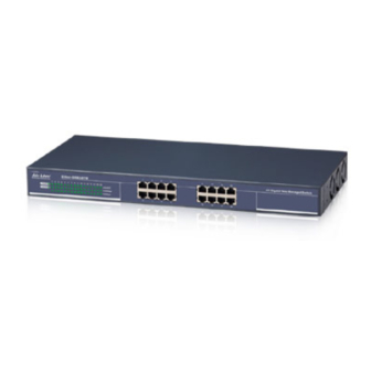
Identifying External Components This chapter describes the front panel, rear panel and LED indicators of the Switch Front Panel The figure below shows the front panels of the Switch. Figure 4. Front panel of 16-port Gigabit Ethernet Switch LED Indicator: Comprehensive LED indicators display the status of the switch and the network (see the LED Indicators chapter below). -
Page 17: Rear Panel
Rear Panel The rear panel of the Switch consists of an AC power connector. The following shows the rear panel of the Switch. Figure 5. Rear panel of the Switch AC Power Connector This is a three-pronged connector that supports the power cord. -
Page 18: Understanding Led Indicators
Understanding LED Indicators The front panel LEDs provides instant status feedback, and, helps monitor and troubleshoot when needed. The Switch LED indicators Power and System LEDs POWER: Power Indicator : When the Power LED lights on, the Switch is receiving power. : When the Power turns off or the power cord has improper connection. -
Page 19: Orts Tatus Led
Ports 1~16 Status LEDs Link/ACT: Link/Activity When the Link/ACT LED lights on, the respective port is successfully connected to an Ethernet network. Blinking : When the Link/ACT LED is blinking, the port is transmitting or receiving data on the Ethernet network. -
Page 20: Configuration
Configuration Through the Web Browser you can configure the Switch such as VLAN, Trunking, QoS… etc. With the attached Web Management Utility, you can easily discover all the Web Management Switch, assign the IP Address, changing the password and upgrading the new firmware. Installing the Web Management Utility The following gives instructions guiding you through the installations of the Web Management utility. -
Page 21: Discovery List
Figure 7. Web Management Utility The Web Management Utility was divided into four parts, Discovery List, Monitor List, Device Setting and Toolbar function, for details instruction, follow the below section. Discovery List This is the list where you can discover all the Web management devices in the entire network. -
Page 22: Monitor List
MAC Address: Shows the device MAC Address. IP Address: Shows the current IP address of the device. Protocol version: Shows the version of the Utility protocol. Product Name: Shows the device product name. System Name: Shows the appointed device system name. Location: Shows where the device is located. - Page 23 View Trap: The Trap function can receive the events that happen from the Web Management Switch in the Monitor List. There is a light indicator behind the “View Trap” button, when the light indicates in green, it means that there is no trap transmitted, and else when it indicates in red, it means that there is new trap transmitted, this is to remind us to view the trap.
-
Page 24: Device Setting
Device Setting You can set the device by using the function key in the Device Setting Dialog box. Configuration Setting: In this Configuration Setting, you can set the IP Address, Subnet Mask, Gateway, Set Trap to (Trap IP Address), System name and Location. Select the device in the Discovery list or Monitor List and press this button, then the Configuration Setting window will pop out as Figure 10, after filling up the data that you want to change,... - Page 25 you need to change the password, fill in the password needed in the dialog box and press “Set” button to proceed the password change immediately. Figure 11. Password Change Firmware Upgrade: When the device has a new function, there will be a new firmware to update the device, use this function to update.
-
Page 26: Toolbar
Toolbar The toolbar in the Web Management Utility have four main tabs, File, View, Options and Help. In the “File TAB”, there are Monitor Save, Monitor Save As, Monitor Load and Exit. Monitor Save: To record the setting of the Monitor List to the default, when you open the Web Management Utility next time, it will auto load the default recorded setting. -
Page 27: Login
The Switch can be configured through the Web Browser. A network administrator can manage, control and monitor the switch from the local LAN. This section indicates how to configure the Switch to enable its smart functions including: Port Setting (Speed/Disable, Duplex mode, Flow Control and Port base QoS) Virtual LAN Group setting (VLAN) Trunk... - Page 28 Figure 13. Or through the Web Management Utility, you do not need to remember the IP Address, select the device shown in the Monitor List of the Web Management Utility to settle the device on the Web Browser. When the following dialog page appears, remain enter the default password "admin"...
-
Page 29: Setup Menu
Figure 15. Device Status Setup Menu When the main page appears, find the Setup menu in the left side of the screen (Figure 16). Click on the setup item that you want to configure. There are eleven options: Port Settings, VLAN Settings, Trunk Setting, Mirror Setting, Device Status, Statistic, System Settings, Trap Setting, Password Setting, Backup Setting and Reset Setting as shown in the Main Menu... -
Page 30: Configuring Setup Setting
Figure 16. Setup menu Configuring Setup Setting Find that there are four items, including Port Settings, VLAN Settings, Trunk Settings and Mirror Settings in Setup menu. Port Settings In Port Settings menu (Figure 17), this page will show each port’s status, press the ID parameter to set each port’s Speed, Flow Control, QoS priority and Link Status. - Page 31 and duplex mode; else this dialog box will show down when the port is disconnected. Figure 17. Port Setting To change the port setting, click on the ID parameter to enter to the selected port to configure its Speed/Disable, Flow control and QoS setting.
-
Page 32: Vlan Settings (Virtual Local Area Network)
selections. Flow Control: This setting determines whether or not the Switch will be handling flow control. Set Flow Control to Enable for avoiding data transfer overflow. Or it sets to Disable; there is either no flow control or other hardware/software management. When the port is set to forced mode, then the flow control will automatically set to Disable. -
Page 33: Trunk Setting
Figure 20. VLAN Settings Trunk Setting The Trunk function enables to cascade two devices with a double times bandwidth (maximum up to 16Gbps in full duplex mode). There are three selections in each group of trunk setting as follow: Group 1: Selection 1(disable), Selection 2(port 1, 2), Selection 3(port 1, 2, 3, 4). Group 2: Selection 1(disable), Selection 2(port9, 10), Selection 3(port 9, 10, 11, 12). - Page 34 one port of a network switch to another port where the packet can be studied. It enables the manager to keep close track of switch performance and alter it if necessary. Configuring the port mirroring by assigning a source port from which to copy all packets and a sniffer port where those packets will be sent.
-
Page 35: Device Status
Device Status Click on the “Status” to present the device status on this screen, it will show the System Status, Port Status, VLAN Status, Trunk Status and Mirror Status.. Press “Refresh” when you need to renew the posted information. -
Page 36: Statistic
Statistic The Statistic Menu screen will show the status of each port packet count. Figure 23. Statistic For Detail packet information, click on the ID parameter as Figure 24. Figure 24. -
Page 37: System Setting
System Setting The System Setting includes the System name, Location name, Login Timeout, IP Address, Subnet Mask and Gateway. Through the Web Management Utility, you can easily recognize the device by using the System Name and the Location Name. The Login Timeout is to set the idle time-out for security issue, when there is no action in running the Web Smart Utility and the time is up, you must re-login to Web Smart Utility before you set the Utility. -
Page 38: Password Setting
the Web Management Utility, set the Trap IP Address of the manager where the trap to be sent. Figure 26. Trap Setting System Events: Monitoring the system’s trap. Device Bootup: a trap when booting up the system. Illegal Login: a trap when there is using a wrong password login, and it will record from where the IP to be login. -
Page 39: Reset Setting
setting of the recorded file. Figure 28. Backup Setting Note: when restoring a recorded file, the current password will not be erased. Reset Setting The Factory Reset button helps you to reset the device back to the default setting from the factory. Be aware that the entire configuration will be reset, the IP address of the device will be set to default setting 192.168.0.1. - Page 40 Figure 30. Logout...
-
Page 41: Technical Specifications
Technical Specifications General Standards IEEE 802.3 10BASE-T Ethernet IEEE 802.3u 100BASE-TX Fast Ethernet IEEE 802.3ab 1000BASE-T Gigabit Ethernet IEEE 802.3x Full Duplex Flow Control Protocol CSMA/CD Data Transfer Ethernet: 10Mbps (half duplex), 20Mbps (full-duplex) Rate Fast Ethernet: 100Mbps (half duplex), 200Mbps (full-duplex) Gigabit Ethernet: 2000Mbps (full-duplex) Topology... - Page 42 Performance Transmits Method: Store-and-forward Filtering Address 8K entries per device Table: Packet 10Mbps Ethernet: 14,880/pps Filtering/Forwardin 100Mbps Fast Ethernet: 148,800/pps g Rate: 1000Mbps Gigabit Ethernet: 1,488,000/pps MAC Address Automatic update Learning: Transmits Method: Store-and-forward RAM Buffer: 512KBytes per device...
Need help?
Do you have a question about the ETHER-GSH16TW and is the answer not in the manual?
Questions and answers