
Related Manuals for AirLive POE-200CAM V2


Summary of Contents for AirLive POE-200CAM V2
-
Page 1: Dome Ip Camera
POE-200CAM v2 1/4 CMOS Dual Stream DOME IP Camera User’s Manual ... -
Page 2: Before You Use This Product
• Use a soft, dry cloth to clean the external surfaces of the device. Stubborn stains can be removed using a soft cloth dampened with a small quantity of detergent solution, then wipe dry. • Do not use volatile solvents such as alcohol, benzene or thinners as they may damage the surface. AirLive POE‐200CAMv2 User’s Manual 1 ... -
Page 3: Table Of Contents
Configuration of Main Menu ..........................11 Chapter 6 Setting ......................... 13 Basic ...................................13 Advance................................27 Chapter 7 CamPro Express User’s Manual ............... 40 Getting Started..............................40 Running the Installation Wizard ........................42 Start Service Program ............................46 Admin Program..............................47 Monitor Program..............................78 Web Monitor...............................87 Multi Playback..............................89 AirLive POE‐200CAMv2 User’s Manual 2 ... - Page 4 APPENDIX A. IIS Installation for Windows Vista .....................96 APPENDIX b. Security Setting in Web Monitor under Vista ..................99 APPENDIX C. Frame Rate & Bit Rate Table......................101 APPENDIX D. Storage Requirement Table ......................103 Chapter 8 Technical Specifications.................. 104 Chapter 9 Glossary......................105 AirLive POE‐200CAMv2 User’s Manual 3 ...
-
Page 5: Chapter 1 Installation
Follow these steps to install the POE-200CAMV2 on your Ethernet: 1. Check the package contents against the list below. 2. Set the device. See IP Installer User Manual on the available methods. 1. Install Ethernet Cable 2. Install Speaker 3. Put on ceiling AirLive POE‐200CAMv2 User’s Manual 4 ... -
Page 6: Package Contents
Language Packs Two screws and plastic wall anchors Screw Pack Adaptor 12V DC, max 6W POE-200CAMv2 Dome IP Camera Camera Power Adapter, DC12V, 1.25A IP Camera Installation CD Quick Setup Guide AirLive POE‐200CAMv2 User’s Manual 5 ... -
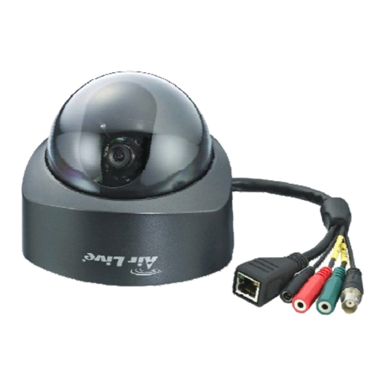
Page 7: Overviews
NO COM D‐ D+ Ground Switch 12V Alarm out device Ground 12V Note Max. 30W Hold the Reset Button for 10 seconds to restore the camera to default AirLive POE‐200CAMv2 User’s Manual 6 ... -
Page 8: Chapter 2 Using Ip Camera Via Mobile Phone
2.5G Mobile Phone Viewing For 2.5G mobile phone viewing, type “<IP>/mobile.wml” into your 2.5G web browser. <IP> is the IP address of your IP camera. AirLive POE‐200CAMv2 User’s Manual 7 ... -
Page 9: Chapter 3 Using Ip Camera Via Web Browser
•If you can’t view the recorded video file (missing video decoder), please install Xvid codec while installing Intelligent IP Installer. (For Windows 98, ME or 2000 server, the codec might not work properly. You’ll need to download Xvid codec 1.0 from the internet. AirLive POE‐200CAMv2 User’s Manual 8 ... -
Page 10: Chapter 4 Initial Accessing The Ip Camera
Initial accessing the IP camera Chapter 4 1. Start your web browser, and enter the IP address or host name of the AIRLIVE IP camera in the Location / Address field of your browser. Note: • If you only want to view the video without setting page, enter “http://<IP>/index2.htm” as your web URL. -
Page 11: Chapter 5 How To Use
Note: • If you only want to view the video without setting page, enter “http://<IP>/index2.htm” as your web URL. 2. Use the default account “admin” and default password “airlive”. Note: • The default user name “admin” and the password are set at the factory for the administrator. You can change them in the Account Menu under Setting on page 25. -
Page 12: Configuration Of Main Menu
Video Buffer: Turn the Video Buffer function On/Off. The Video Buffer function makes the streaming more smoothly in unsteady network environment, but might cause a little delay in live viewing. 5.2.3 Image Setup You can use the tool bar to optimize video brightness, contrast, and saturation. AirLive POE‐200CAMv2 User’s Manual 11 ... - Page 13 It means the speakers of your computer are turned on to transmit the sounds from the connected IP camera(s). Similarly, means you can broadcast to the connected IP camera(s) via the Ethernet using your microphone. Video play buttons: :Pause the current video :Play the video. :Stop the current video. :Record the current video. AirLive POE‐200CAMv2 User’s Manual 12 ...
-
Page 14: Chapter 6 Setting
Click on the “Basic” folder to display the sub folders, including System, Camera, Network, and Security. 6.1.1 System Information The Information page provides you with product factory information, including Product name, Firmware version, and Web version. Day & Time AirLive POE‐200CAMv2 User’s Manual 13 ... - Page 15 Reboot:Click this button to reboot the device. A confirmation dialogue will appear. Click OK to proceed. It takes about two minutes to reboot the device. Factory default:Click this button to reset the device to the factory default settings. A confirmation dialogue will AirLive POE‐200CAMv2 User’s Manual 14 ...
- Page 16 Media Player, QuickTime, etc…) Image Rotate:Enables user to mirror or flip the display screen. Night Mode:Turn Night Mode ON/OFF. Lighting:Choose the lighting environment among 50Hz, 60Hz and Outdoor. White Balance:Choose the White Balance to Auto, Fluorescent, Incandescent and Black&White. AirLive POE‐200CAMv2 User’s Manual 15 ...
- Page 17 Multicast address: Specify the multicast server address. Video / Audio Port: Specify the transmission port number of the video data. Specify an even number from 1024 to 65534. Time-To-Live: Set the maximum TTL that multicast can pass through. AirLive POE‐200CAMv2 User’s Manual 16 ...
- Page 18 512, 768, 1024, 1280, 1536 and 2048 kbps. Note: • The selected frame rate and bit rate are a tentative value. The actual frame rate and bit rate may be different according to the image size, the shooting scene or the network condition. AirLive POE‐200CAMv2 User’s Manual 17 ...
- Page 19 Frame rate:Set the frame rate of the MPEG4 image. Selectable values are 5, 10, 15, 20 fps. The unit “fps” stands for “frames sent per second”. Quality Fixed Bit rate:Set the bit rate of MPEG4 image transmission for a line. Selectable values are 64, 32, and 16kbps. AirLive POE‐200CAMv2 User’s Manual 18 ...
- Page 20 Frame rate:Set the frame rate of the MJPEG image. Selectable values are 5, 10, 15 fps. The unit “fps” stands for “frames sent per second”. Quality Auto:The quality will be automatically decided. Fixed quality:The selectable values are Medium, Standard, Good, Detailed and Excellent. AirLive POE‐200CAMv2 User’s Manual 19 ...
- Page 21 • When you have set the HTTP port number to a number other than 80 on the Network setting page or in the Setup Program, access the device by typing the IP address of the device on the web browser as follows: Example: when HTTP port number is set to 2000 http://192.168.1.100:2000/ AirLive POE‐200CAMv2 User’s Manual 20 ...
- Page 22 Use the following DNS server address:Select this when you set the fixed address as the IP address of DNS server. Primary DNS server:Enter the IP address of the primary DNS server. Secondary DNS server:Enter the IP address of the secondary DNS server. AirLive POE‐200CAMv2 User’s Manual 21 ...
- Page 23 Password:Enter the password for authentication necessary for DDNS connections. Type it up to 32 characters. Re-type password:Re-type the password to confirm. Host name:Enter the host name that is registered to the DDNS server. Note: • When you want to use DDNS function, you need to register an account in DDNS server first. AirLive POE‐200CAMv2 User’s Manual 22 ...
- Page 24 MJPEG viewer port:Enter the MJPEG viewer port number and default MJPEG viewer port is 8070. MJPEG viewer port (SSL): Enter the MPEG4 SSL viewer port and default is 8071. MPEG4 RTSP port: Enter the MPEG4 RTSP port, default value is 8050 for computer view, 8030 for mobile view. AirLive POE‐200CAMv2 User’s Manual 23 ...
- Page 25 Administrator e-mail address:Type the Administrator e-mail address up to 64 characters. This address is used for reply mail and sending system messages from the SMTP server. Subject:Type the subject/title of the e-mail up to 64 characters. With respect to mail which is sent according to the IP notification. AirLive POE‐200CAMv2 User’s Manual 24 ...
- Page 26 User name:Set a user name between 5 and 16 characters. Password:Set a password between 5 and 16 characters. Re-type password:Re-type the password to confirm. Viewer Mode:Set a user to Admin, Operator or Viewer mode. Viewer authentication:Allows any viewer direct access to Live View. AirLive POE‐200CAMv2 User’s Manual 25 ...
- Page 27 HTTPS function, then set up the connection policy for different users, and click “Set Policy” to apply the settings. Create & Install: Create a self-signed certificate for HTTPS to recognize. Installed Certificate: Display or remove the properties of the installed certificate. HTTPS Connection Policy: Set HTTPS connection policy for different level of users. AirLive POE‐200CAMv2 User’s Manual 26 ...
-
Page 28: Advance
Retype password:To confirm the password, type the same characters as you typed in the Password box. Passive mode:Set whether you use the passive mode of FTP server or not when connecting to FTP server. Select On to connect to FTP server using the passive mode. AirLive POE‐200CAMv2 User’s Manual 27 ... - Page 29 Effective period:Set the period when the periodical sending is effective. Always:The periodical sending is always effective. Schedule:You can specify the period when the periodical sending is effective in the schedule setting in the other section. Click Schedule and the setting menu for the effective period is displayed. AirLive WL‐2000CAM User’s Manual 28 ...
- Page 30 You can set to send an image file to FTP server periodically by selecting On to send the image file to FTP server linked with setting period. Remote path:Type the remote path up to 64 characters. Image file name:Type the file name of the image sent to FTP server up to 10 alphanumeric characters, ‐ (hyphen) and _ (under score). Suffix:Select a suffix to be added to the file name sent to FTP server. None:The name of the sent file will be the Image file name. Date & time : The date & time suffix is added to the Image file name. The date & time suffix consists of lower two‐digits of year (2 digits), month (2 digits), date (2 digits), hour (2 digits), minute (2 digits) and second (2 digits), and consecutive number (2 digits), thus 14‐digit number is added to the file name. Sequence number:A consecutive number is added to the Image file name. Sequence number clear:Click Clear and the suffix of the sequence number returns to 1. Interval:Set the periodical sending is effective interval. Min value is 1 min and Max value is 24 hours. Effective period:Set the period when the periodical sending is effective. Always:The periodical sending is always effective. Schedule:You can specify the period when the periodical sending is effective in the schedule setting in the other section. Click Schedule and the setting menu for the effective period is displayed. AirLive POE200CAMv2 User’s Manual 29 ...
- Page 31 On: When authentication is necessary an e-mail is sent, select one of the authentication methods from the followings. SMTP: Select if SMTP authentication is necessary when an e-mail is sent. POP before SMTP: Select if POP before SMTP authentication is necessary when an e-mail is sent. AirLive POE‐200CAMv2 User’s Manual 30 ...
- Page 32 Message:Type the text of the e-mail up to 384 characters. (A line break is equivalent to 2 characters.) 6.2.2.2 Alarm Sending Set to send the mail with connection to the alarm detection by the external sensor input or by the built-in motion detection function. AirLive POE200CAMv2 User’s Manual 31 ...
- Page 33 • Motion Detection works only when the Video mode is set to MPEG4 and the Cropping is set to Off. 6.2.2.3 Periodical Sending You can set to send an image file by SMTP server periodically by selecting On to send the image file by SMTP server linked with setting period. AirLive POE‐200CAMv2 User’s Manual 32 ...
- Page 34 HTTP server. HTTP client setting menu is composed of two tabs, General and Alarm sending. 6.2.3.1 General HTTP event: Set up the HTTP server URL, port, user ID, password, and proxy server settings. AirLive POE200CAMv2 User’s Manual 33 ...
- Page 35 Effective period:Set the period when the periodical sending is effective. Always:The periodical sending is always effective. Schedule:You can specify the period when the periodical sending is effective in the schedule setting in the other section. Click Schedule and the setting menu for the effective period is displayed. AirLive POE‐200CAMv2 User’s Manual 34 ...
- Page 36 There are three Motion Detection functions as sensors to set for different detecting zones. Each one has Threshold and Sensitivity inputs which you can adjust to specific zone sequentially. Motion Detection function can support to FTP, SMTP and Alarm output for capturing and sending images or starting alarm output. AirLive POE200CAMv2 User’s Manual 35 ...
- Page 37 1. Click On to Motion Detection 1 choose one of eight orders. 2. A detecting zone 1 appears and use mouse to adjust and move the zone boundaries and position. 3. Use tool bar to set Threshold and Sensitivity value. AirLive POE‐200CAMv2 User’s Manual 36 ...
- Page 38 When you click Alarm Input on the Advance mode menu, the Alarm input setting menu appears. You can set in this menu to control the external alarm input of I / O port on the rear of the device linked to FTP, SMTP, and HTTP sending function. AirLive POE200CAMv2 User’s Manual 37 ...
- Page 39 You can set the Pre-alarm image and audio (the image and audio before the alarm detection) and the Post - alarm image and audio. These can be set when Alarm sending FTP client setting menu or Image memory setting menu is set to On, and besides when Use alarm buffer is selected. AirLive POE‐200CAMv2 User’s Manual 38 ...
- Page 40 Post alarm period: Type it with recording time of the image/audio after the alarm detection. Note:The value of Recording capacity differs depending on Image size, Bitrate (for MPEG4) and Image quality (for MPEG4 and MJPEG) in the camera setting menu. AirLive POE200CAMv2 User’s Manual 39 ...
-
Page 41: Chapter 7 Campro Express User's Manual
AirLive CamPro Express includes the following programs: 1. Start Service: This program manages video recording, input/output events and alarm triggering; it is running as a background program of AirLive CamPro Express comes with PC boot up, for detail please refers to Section C. - Page 42 1024 x 768 (XVGA) or above Networking Suggestion AirLive CamPro Express is optimized for small-scale project, simple LAN or simple WAN environment. Place the system behind firewall or IP sharing device to efficiently protect this system from hackers’ attack. AirLive POE200CAMv2 User’s Manual ...
-
Page 43: Running The Installation Wizard
【Step 3】The Installshield Wizard will check if IIS is installed at your system. If not, you can continue installing AirLive CamPro Express, but you will not be able to use the WEB monitoring feature without IIS. To Install IIS, do the following, Click “Start”. - Page 44 【Step 4】Click “Next” to begin the installation process. 【Step 5】Please read the License Statement and select “Yes” to accept and continue. 【Step 6】Choose Setup type and click “Next” to continue. AirLive POE200CAMv2 User’s Manual 43 ...
- Page 45 If you would like to view video image via a browser from remote locations, select Web Component. 【Step 9】Select Program Folder Specify the Program Folder where AirLive CamPro Express icons will be installed to. Click “Next” to continue. AirLive POE‐200CAMv2 User’s Manual 44 ...
- Page 46 【Step 11】Click “Next” to continue 【Step 12】Installshield Wizard Complete; click “Finish” to complete the setup. The system should start AirLive CamPro Express in 1 to 3 minutes, and the icon of AirLive CamPro Express ( ) appear in task bar of screen’s lower-right corner.
-
Page 47: Start Service Program
Please insert AirLive CamPro Express CD into CD-ROM drive. Go to AirLive CamPro Express\Client directory to execute Setup.exe. 【Note】 (1) You may freely install Client version to whichever computer you want. (2) The rest steps are same as installing Server version. -
Page 48: Admin Program
7.3.2 Shutting Down the Start Service Program 【Step 1】Right click on the AirLive CamPro Express Server’s start service icon from the system tray. 【Step 2】Click “Exit” and you will be asked with a dialog “Are you sure you to exit the system?”... - Page 49 Receive video through server: If you want to remote control AirLive CamPro Express server from client which is not within intranet, then check this box. Password: The default password of 【Note】 Administrator is blank. It is recommended that you change password for security management, please go to User Group section to change the password.
- Page 50 If your system does not display the screen properly, please check if your display resolution is at least 1024 x 768, and that the font size is Windows system default. AirLive CamPro Express does not support font sizes larger than the Windows system default one.
- Page 51 China Telecom is the default SMS service provider. If you wish to add a local SMS provider, please consult your local distributor for information on SMS providers that are able to provide service for AirLive CamPro Express 【Step1】Click “Add” to bring up the SMS window and enter the related information about your SMS provider.
- Page 52 DNS Setting It is designed for the DNS resolution between AirLive CamPro Express server and IP device. Your video IP device will connect server via IP address of server if you did not enable DNS Resolution. But your IP device will connect server via Domain Name which your server registered, so that alarm action could be executed.
- Page 53 IP changes periodically due to the policy of your network administrator, please check “Enable DNS resolution”, so any alert message could be delivered to AirLive CamPro Express from camera no matter what IP your server is assigned. Enter the Domain Name your computer registered to “DNS of this PC”...
- Page 54 Allocation: The storage allocation should be no less than 2 GB. Threshold: When the image data exceeds 90% of allocation, AirLive CamPro Express will trigger a warning message to related parties. Threshold no less than 1.8 GB. Reservation: AirLive CamPro Express will overwrite historical data when it reaches 80% of allocation.
- Page 55 Alarm Ring Setting: there are 4 sounds effect to be selected. Any system event will trigger alarm action, please refers to Section 7.6.8.1.2 LanCam Setting – Alarm Action for detail. AirLive POE‐200CAMv2 User’s Manual 54 ...
- Page 56 Motion Rectangle By selecting Motion Rectangle button from the Menu Bar, you can set the square size of detected area. AirLive POE200CAMv2 User’s Manual 55 ...
- Page 57 【Step 1】Select User icon in the System Setup area, then click the New User button the Menu Bar. 【Step2】Enter user information in the “General” Tab. 【Note】For security concern, it is recommended to assign Password and tick the box for password changing and validation. AirLive POE‐200CAMv2 User’s Manual 56 ...
- Page 58 Setting Button will display in the Menu Bar accordingly. Then click the Edit User button in the Menu Bar. 【Step2】Modifying user Information You may change the information by modifying the general information or user belongs of that user. AirLive POE200CAMv2 User’s Manual 57 ...
- Page 59 【Step1】 Select the User icon in the System Setup area, then click Add User Group button the Menu Bar to add the user group’ s data. 【Step2】 Give a name to the new group and group the selected users here in one step. AirLive POE‐200CAMv2 User’s Manual 58 ...
- Page 60 Then click the Edit User button in the Menu Bar. 【Step2】Modify User group Information. You may change the information by modifying the general information or function of that user group. AirLive POE200CAMv2 User’s Manual 59 ...
- Page 61 7.4.5 Area and eMap management Area refers to the geography and device scope of AirLive CamPro Express. Area is a prerequisite of any device setting (device includes: video server, LanCam, camera image, relay or sensor), AirLive CamPro Express provides multi-areas to meet user different requirement.
- Page 62 Auto Add Device: This button allows you to automatically search all IP cameras/Video server that are located at the same subnet within a LAN environment. Auto add device just support the IP cameras/Video server with UPnP supported. AirLive POE200CAMv2 User’s Manual 61 ...
- Page 63 【Step2】Click Add Area button from the Menu Bar. An Area Setting window will pop up. Enter the name to the “Area Name” textbox. 【Step3】Click “Create” to save setting, a newly created area demonstrate as following: Before Add Area After Add Area AirLive POE‐200CAMv2 User’s Manual 62 ...
- Page 64 Resize eMap Icon 【Step1】 Select Device Ratio button in the Menu Bar. A Resize eMap icon window pops up. 【Step2】Select the ratio of device and click “OK”, the icon display in eMap interface will change it’s ratio accordingly. AirLive POE200CAMv2 User’s Manual 63 ...
- Page 65 New device should be added and configured in AirLive CamPro Express Admin program. The following section will explain the details of LanCam, video server, and I/O Controller setting. The supported H/W manufactures and models for each device can be found in the AirLive CamPro Express Hardware Support list.
- Page 66 【Note】 You can edit the device information through LanCam/Video Server/IO Controller setting. LanCam Select LanCam icon When select LanCam icon in System Setup area, the buttons display in Menu Bar as left bar. AirLive POE200CAMv2 User’s Manual 65 ...
- Page 67 Remove LanCam: to remove the configuration of a selected LanCam including the image under it. HW Password: to change the User Name or Password of selected LanCam from AirLive CamPro Express or to sync with the direct change in device.
-
Page 68: Image Setting
Save Location Schd1: here display the alias of recorded path. For detail, please refer to Section D.3.5. Storage. Recording Type: Schedule recording could be activated by clicking to select “Always” or “Schedule”, and check Recording Type of “Motion Detection” to significantly reduce the storage of schedule recording. AirLive POE200CAMv2 User’s Manual 67 ... - Page 69 【Step1】Select the Image icon and click Image Setting button to bring up the Image setting window. 【Step2】Select “Recording Type” Check the Schedule in Recording Type first, and you will find that the Schedule Setting button is enabled. AirLive POE‐200CAMv2 User’s Manual 68 ...
- Page 70 If an error message pops up, please check if any related device is unable to connect due to the information described in Error Message window. Solve the problem, and then go back to LanCam Setting button to configure this device again. AirLive POE200CAMv2 User’s Manual 69 ...
- Page 71 【Step5】Click “Add”… to add new Alarm Action.(Detail please refers to Section 7.6.8.1.2 LanCam Setting – Image Alarm) 【Step6】Click “OK” to save all alarm action configuration (including “Add”, “Modify”, “Remove” and “Copy”) and dismiss this window. Click “Cancel” to ignore all configurations and dismiss this window. AirLive POE‐200CAMv2 User’s Manual 70 ...
- Page 72 Set alarm triggered by Camera-image 1 and records the video of Camera-image 2: Select Camera-image 1 icon in System setup Area and click Image Alarm button from Menu bar, then select “Alarm action” by Recording and “Acting Device” by “Camera-image 2”. “Alarm Live Video” Scenario AirLive POE200CAMv2 User’s Manual 71 ...
-
Page 73: Preset Setting
[Note] This will also overwrite the previous setting stored in this preset location. Preset locations can not be removed. Set the other preset locations in the same process. Click “Exit” to leave this dialog. AirLive POE‐200CAMv2 User’s Manual 72 ... -
Page 74: Motion Detection
【Note】The size of red frame is configurable in Motion Detection Granularity, details please refer to Section D.3.8. Motion Rectangle. Different camera may have different interface for motion detection adjustment. Some may require you to install Active-X components. AirLive POE200CAMv2 User’s Manual 73 ... -
Page 75: Image Quality
Current UserName/Password: The default value for current username and current password is same as device default. New UserName/Password: Change information and save to both AirLive CamPro Express and Web configuration of selected device. 【Step2】Click OK to save the setting. AirLive POE‐200CAMv2 User’s Manual 74 ... -
Page 76: Sensor Setting
【Note】When to configure? AirLive CamPro Express system default are same as device default, only when you want to change PW from AirLive CamPro Express or when you find the PW of device has been changed in web configuration program Sensor (Digital Input) Many video gateways and LAN cameras has GPIO port. - Page 77 System Setup tree, the toolbar becomes: The button on the right will only appear if you select a configured relay. Relay Settings Click [Relay Setting] button and the Relay Setting dialog will appear, as shown below: AirLive POE‐200CAMv2 User’s Manual 76 ...
- Page 78 Click the [Remove Relay] button to remove the selected Relay. You will be asked to confirm the deletion. Tools in Menu Bar of eMap interface eMap tools bar will appear above the eMap Interface area after the picture that you uploaded to the eMap Interface area. AirLive POE200CAMv2 User’s Manual 77 ...
-
Page 79: Monitor Program
(f) Default Size:back to the default size and location 7.5 Monitor Program AirLive CamPro Express Monitor program could be selected from the Program Path; user may log on monitor program through Monitor.exe or Web monitor. You may access AirLive CamPro Express server thru IE browsing by entering the URL. - Page 80 Video display area display video of single camera or split screen of multiple cameras, when you want to control a camera in your monitor program, you may click the split-ed screen and it will be covered by a red-frame. AirLive POE200CAMv2 User’s Manual 79 ...
- Page 81 Live video could be manually recorded in the local computer by clicking the Local Record button, so that user could record live video easily and save in any local computer. Start Local Record 【Step1】 Select a camera from display area by a red frame. 【Step2】Click “Local Record” button to start the recording. AirLive POE‐200CAMv2 User’s Manual 80 ...
- Page 82 Click “Pause” button to get a still image first, then click “Snapshot” button to save the image in JPG format (please refer to Section 7.7.5.4 Snapshot) Transfer to AVI Click the “Record AVI” to export the image to the AVI format. Assign a file name, a location, and a vide compression option. AirLive POE200CAMv2 User’s Manual 81 ...
- Page 83 CIF or 4CIF button to change resolution to 352x240/320x288(NTSC/PAL) or 704x480/704x576 (NTSC/PAL). (CIF/4CIF/Screen display: AirLive CamPro Express resolution button will change text according to the device resolution setting. While video display in split screen, the resolution...
- Page 84 7.5.6 PT Control Interface If your IP camera or analogue camera under Video Server has PTZ function, you may use AirLive CamPro Express control interface to view different angle of Camera by clicking button on PT Control Interface. 1: PT Speed: You may select the drop list to change speed of camera movement.
- Page 85 【Step3】 Click the “Query”, a query result will appear in the upper left table. 【Step4】Select the file you want to display. Take a Snapshot (For detail, please refer to 7.7.5.4 Snapshot) Record AVI (For detail, please refer to Section 7.7.5.2 Local Play – Transfer to AVI) AirLive POE‐200CAMv2 User’s Manual 84 ...
- Page 86 【Step4】You can print out the query by clicking the “Print” or “Export” button. 【Step5】Select the Export support list, assign export format and destination support. Text, Excel and Word are all supported. 【Step6】Select an alarm log and click it to bring up a window to get the alarm action detail. AirLive POE200CAMv2 User’s Manual 85 ...
- Page 87 When the image rotation is enabled. 7.8 Alarm eMap An E-Map with the device that triggered the alarm will pop up in the E-Map display area. 7.9 Alarm Notification Log The most up-to-date alarm was logged in the alarm notification log. AirLive POE‐200CAMv2 User’s Manual 86 ...
-
Page 88: Web Monitor
Logon Web Monitor Log on Web Monitor from server Start Program Files AirLive CamPro Express Web Monitor。 Log on Web Monitor from client You may open IE browser and entering the URL in the format of server IP and “\Web”. (Example http://localhost/Web/) 【Step1】System will bring up IE and... - Page 89 【Note】Web Monitor is for viewing convenience, so there are few differences between Web Monitor and Monitor program, and which are (1) no alarm notification log (2) no alarm eMap (3) no schedule status display in Web Monitor (4) no relay setting. AirLive POE‐200CAMv2 User’s Manual 88 ...
-
Page 90: Multi Playback
7.7.1 Running Multi Playback Program 【Step1】Select Start/All Programs/AirLive CamPro Express/ Multi playback. 【Step2】System Log on window. If this is the first time you login, use Administrator as default user name and leave the password blank, then click OK to log into the system. - Page 91 Recording History Query: provides functions to add display group and query all recording (within a 24 hours period) in a display group. User can select any hour in this period to start playback. Recording History Playback: provides playback function for all playback groups with a given date/time. AirLive POE‐200CAMv2 User’s Manual 90 ...
- Page 92 Use the split screen to select playback location to select/unselect cameras in the group. Click “OK” button to save the setting and close the setting window or click “Apply” button to save the setting and remain in this setting window. AirLive POE200CAMv2 User’s Manual 91 ...
- Page 93 “Delete” and then click “OK” to confirm. 【Step 3】Query result display. After you have finished selecting a group and date, the system will show all historical recording for cameras in that group shown to the left. AirLive POE‐200CAMv2 User’s Manual 92 ...
- Page 94 Move the slider toward “slow” will slow down the playback. Move the slider toward fast will increase the playback speed. Playback Control: Use the pointer in the control area to operate the video. AirLive POE200CAMv2 User’s Manual 93 ...
- Page 95 Video Display and Query Result Area Depending on the function in use and query criteria selected, this area will show either query result for recording history or multiple channel playback for historical recordings AirLive POE‐200CAMv2 User’s Manual 94 ...
- Page 96 Query Criteria Area Query criteria area provides user ability to specify query criteria for searching historical recording. 7.7.3 Exiting the Multi Playback Click the “Exit” button to exit the Multi Playback program. AirLive POE200CAMv2 User’s Manual 95 ...
-
Page 97: Appendix A. Iis Installation For Windows Vista
APPENDIX A. IIS Installation for Windows Vista To Install IIS for Windows Vista version, please do the followings: STEP 1: Click “Continue”. STEP 2: Start Control Panel Program and Features Click Turn Windows features on or off. The Windows Features dialog box opens. AirLive POE‐200CAMv2 User’s Manual 96 ... - Page 98 Management Compatibility”, then select the “IIS 6 Management Console, IIS 6 Scripting Tools, IIS 6 WMI Compatibility, IIS Metabase and IIS 6 Configuration Compatibility“ check box. AirLive POE200CAMv2 User’s Manual 97 ...
- Page 99 STEP 5: Double-click (or expand) World Wide Web Services, double-click Application Development Features, then select the ASP and ISAPI Extensions check box. AirLive POE‐200CAMv2 User’s Manual 98 ...
-
Page 100: Appendix B. Security Setting In Web Monitor Under Vista
APPENDIX b. Security Setting in Web Monitor under Vista Launch Internet Explorer STEP 1: Browser Select Internet Options Select Security tab Choose Trusted sites and click Sites button. Input the web server IP, STEP 2: example: http://127.0.0.1. AirLive POE200CAMv2 User’s Manual 99 ... - Page 101 STEP 3: Select Trusted sites then click “Custom level…” button. STEP 4: Find Initialize and script ActiveX controls not marked as safe option, then select “Enable”. AirLive POE‐200CAMv2 User’s Manual 100 ...
-
Page 102: Appendix C. Frame Rate & Bit Rate Table
1536 1600 320*240 1024 1000 320*240 1024 1000 320*240 320*240 160*120 1024 160*120 1024 160*120 160*120 160*120 160*120 A.3 MJPEG @ 15fps / kbps Quality 640*480 320*240 160*120 Excellent 4000 1500 Detailed 2400 Good 1600 Standard 1300 Medium AirLive POE200CAMv2 User’s Manual 101 ... - Page 103 4000 640*480 Excellent 1600 640*480 Good 1600 640*480 Good 640*480 Medium 640*480 Medium 320*240 Excellent 1500 320*240 Excellent 320*240 Good 320*240 Good 320*240 Medium 160*120 Medium 160*120 Excellent 160*120 Excellent 160*120 Good 160*120 Good 160*120 Medium 160*120 Medium AirLive POE‐200CAMv2 User’s Manual 102 ...
-
Page 104: Appendix D. Storage Requirement Table
22.2 640*480 1536 18.5 640*480 1536 17.9 640*480 1024 10.5 640*480 1024 10.5 640*480 640*480 320*240 1536 15.8 320*240 1536 16.9 320*240 1024 10.5 320*240 1024 10.5 320*240 320*240 160*120 1024 10.0 160*120 1024 160*120 160*120 160*120 160*120 AirLive POE200CAMv2 User’s Manual 103 ... -
Page 105: Chapter 8 Technical Specifications
Simultaneous Motion JPEG and MPEG-4 Video Firmware upgrades over HTTP, (Dual streaming) streaming firmware available at www.airlive.com Controllable Frame rate and bandwidth Pentium 4 1.8GHz (or equivalent AMD) Minimum web Support Unicast and Multicast 64 MB RAM graphic cards... -
Page 106: Chapter 9 Glossary
JPEG are examples of image file types that contain bitmaps. Because a bitmap uses this fixed raster method, it cannot easily be rescaled without losing definition. Conversely, a vector graphic image uses geometrical shapes to represent the image, and can thus be AirLive POE200CAMv2 User’s Manual 105 ... - Page 107 CMOS chips require less power than chips using just one type of transistor. CMOS image sensors also allow processing circuits to be included on the same chip, an advantage not possible with CCD sensors, which are also much more expensive to produce. AirLive POE‐200CAMv2 User’s Manual 106 ...
- Page 108 Each user within a domain has an account that usually allows them to log in to and use any computer in the domain, although restrictions may also apply. The domain server is the server that authenticates the users on the network. Duplex - See Full-duplex. AirLive POE200CAMv2 User’s Manual 107 ...
- Page 109 Transmission of data in two directions simultaneously. In an audio system this would describe for example, a telephone systems. Half-duplex also provides bi-directional communication, but only in one direction at a time, as in a walkie-talkie system. See also Simplex. AirLive POE‐200CAMv2 User’s Manual 108 ...
- Page 110 A (network) hub is used to connect multiple devices to the network. The hub transmits all data to all devices connected to it, whereas a switch will only transmit the data to the device it is specifically intended for. AirLive POE200CAMv2 User’s Manual 109 ...
- Page 111 (and automatically) by DHCP. An IP address consists of four groups (or quads) of decimal digits separated by periods, for example, 130.5.5.25. Different parts of the address represent different things. Some part will represent the AirLive POE‐200CAMv2 User’s Manual 110 ...
- Page 112 Image quality is controlled by adjusting the compression level, which in turn provides control over the file size, and thereby the bit rate. High-quality individual images from the Motion JPEG stream are easily extracted. AirLive POE200CAMv2 User’s Manual 111 ...
- Page 113 NTSC is the television and video standard in the United States. NTSC delivers 525 lines at 60 half-frames/second. NWay - is a telecommunications protocol used to automatically negotiate the highest available transmission speed between network devices. The NWay protocol is also known as auto-negotiation or auto-sensing. AirLive POE‐200CAMv2 User’s Manual 112 ...
- Page 114 Computer monitors do not need interlace to show the picture on the screen, but instead show them progressively, on one line at a time in perfect order, i.e. 1, 2, 3, 4, 5, 6, 7 etc., so there is virtually no AirLive POE200CAMv2 User’s Manual 113 ...
- Page 115 RTP (Real-Time Transport Protocol) - RTP is an Internet protocol for the transport of real-time data, for example, audio and video. It can be used for media-on-demand as well as interactive services such as Internet telephony. AirLive POE‐200CAMv2 User’s Manual 114 ...
- Page 116 SNMP (Simple Network Management Protocol) - SNMP forms part of the Internet Protocol suite, as defined by the Internet Engineering Task Force. The protocol can support monitoring of network-attached devices for any conditions that warrant administrative attention. AirLive POE200CAMv2 User’s Manual 115 ...
- Page 117 These two protocols (SSL is succeeded by TSL) are cryptographic protocols that provide secure communication on a network. SSL is commonly used over HTTP to form HTTPS, as used for example, on the Internet for electronic financial transactions. SSL uses public key certificates to verify the identity of the server. AirLive POE‐200CAMv2 User’s Manual 116 ...
Need help?
Do you have a question about the POE-200CAM V2 and is the answer not in the manual?
Questions and answers