
Related Manuals for Tektronix WFM90D


Summary of Contents for Tektronix WFM90D
-
Page 1: User Manual
User Manual WFM90D and WFM91D Handheld Waveform, Vector, Picture, and Audio Monitor 071-1142-01 This document supports firmware version 2.14 and above. www.tektronix.com... - Page 2 Copyright © Tektronix, Inc. All rights reserved. Tektronix products are covered by U.S. and foreign patents, issued and pending. Information in this publication supercedes that in all previously published material. Specifications and price change privileges reserved. Tektronix, Inc., P.O. Box 500, Beaverton, OR 97077...
- Page 3 Tektronix, with shipping charges prepaid. Tektronix shall pay for the return of the product to Customer if the shipment is to a location within the country in which the Tektronix service center is located. Customer shall be responsible for paying all shipping charges, duties, taxes, and any other charges for products returned to any other locations.
-
Page 5: Table Of Contents
....... . . 2- - 4 WFM90D and WFM91D User Manual... - Page 6 ....... 2- - 21 Viewing Serial Digital Signals ..... . . 2- - 21 WFM90D and WFM91D User Manual...
- Page 7 2- - 52 Using the Time-Out Mode ......2- - 53 WFM90D and WFM91D User Manual...
- Page 8 Instrument Adjustment ....... B- - 2 WFM90D and WFM91D User Manual...
- Page 9 ......2- - 2 Figure 2- - 2: WFM90D and WFM91D side panels ..
- Page 10 ....A- - 11 Table A-10: Certifications and compliances ... . . A- - 13 WFM90D and WFM91D User Manual...
-
Page 11: General Safety Summary
If you suspect there is damage to this product, have it inspected by qualified service personnel. Do Not Operate in Wet/Damp Conditions. Do Not Operate in an Explosive Atmosphere. Keep Product Surfaces Clean and Dry. WFM90D and WFM91D User Manual... - Page 12 For the location of a local battery recycler in the U.S. or Canada, please contact: RBRC (800) BATTERY Rechargeable Battery Recycling Corp. (800) 227-7379 P.O. Box 141870 www.rbrc.com Gainesville, Florida 32614 WFM90D and WFM91D User Manual viii...
-
Page 13: Preface
Preface This manual is a guide for operators of the WFM90D and WFM91D Handheld Waveform, Vector, Picture, and Audio Monitor. Manual Structure This manual contains the following information: Getting Started provides a product description and a list of available options and accessories. -
Page 14: Contacting Tektronix
This phone number is toll free in North America. After office hours, please leave a voice mail message. Outside North America, contact a Tektronix sales office or distributor; see the Tektronix web site for a list of offices. WFM90D and WFM91D User Manual... -
Page 17: Product Description
Product Description The handheld, self-contained, Tektronix WFM90D and WFM91D television waveform monitors can monitor analog and digital signals. The monitors provide composite and component waveform displays as well as vector and picture displays. These monitors can be used in the traditional in-house applications of television production, post-production, and signal transmission. - Page 18 Product Description WFM90D and WFM91D User Manual 1- 2...
-
Page 19: More Information
H A tutorial covering basic instrument operation starts on page 2- - 39. H Detailed menu descriptions begin on page 2- - 25. H A complete listing of instrument performance specifications is located in Appendix A. WFM90D and WFM91D User Manual 1- 3... - Page 20 Product Description WFM90D and WFM91D User Manual 1- 4...
-
Page 21: Options And Accessories
Options and Accessories This section lists the options and accessories for the WFM90D and WFM91D. You can order options and accessories with the monitor or purchase them separately through a Tektronix field office or distributor. When ordering, include the option or part number and the description. -
Page 22: Accessories
Options and Accessories Accessories Standard accessories are shipped with every instrument. The standard accessories for the WFM90D and WFM91D and the Tektronix part numbers to use when ordering are listed in Table 1- - 2. Table 1- 2: Standard accessories Description Quantity... -
Page 23: Installation
CONFIG menu (refer to page 2- - 31). Power Source The WFM90D and WFM91D handheld monitors are designed to operate from either six C-cell alkaline batteries, a rechargeable NiMH battery pack, or an AC adapter wall unit producing 12 VDC. -
Page 24: Recharging The Nimh Batteries
Press in on the top portion of the battery connector tab and then pull up gently. To replace the NiMH battery pack, use only the Tektronix recharge- able NiMH battery pack, part number 146- - 0107- - 01. Do not use any other battery pack. -
Page 25: Figure 1- 1: Removing The Nimh Battery Pack
Installation Press Figure 1- 1: Removing the NiMH battery pack WFM90D and WFM91D User Manual 1- 9... -
Page 26: Replacing The Alkaline Batteries
Installation Replacing the Alkaline Batteries You can use six alkaline batteries to power the WFM90D and WFM91D, however, the battery life may be limited. NOTE. Always replace all of the alkaline batteries at the same time. The polarity of the alkaline batteries must be correct for the instrument to operate. -
Page 27: Mechanical Installation
To attach the hood to the instrument, attach the supplied Velcro strips to the sides of the instrument, and then press the flaps of the viewing hood onto the strips as shown in Figure 1- - 3. Figure 1- 3: Installing the viewing hood WFM90D and WFM91D User Manual 1- 11... -
Page 28: Desk Stand
The desk stand holds the monitor upright on a flat surface. Insert the prongs of the stand into the holes in the back of the instrument as shown in Figure 1- - 4. Figure 1- 4: Installing the desk stand WFM90D and WFM91D User Manual 1- 12... -
Page 29: Travel Case
3. Spare batteries for the handheld monitor. 4. Spare batteries for the handheld generator. 5. Handheld generator, desk stand, and carrying straps. 6. AC adapter(s). Figure 1- 5: Packing the Option 33 travel case WFM90D and WFM91D User Manual 1- 13... -
Page 30: Incoming Inspection
Installation Incoming Inspection Save the shipping carton and packing materials in case you need to ship the monitor to a Tektronix Service Center for service or repair. Check that the following standard accessories are included: H User manual H 120 V wall unit power adapter, North American H Carrying pouch NOTE. -
Page 31: Packaging For Shipment
Installation Packaging for Shipment If you ship an instrument to a Tektronix Service Center, follow these packaging instructions: 1. Attach a tag to the instrument showing: the owner, complete address and phone number of someone at your firm who can be contacted, the instrument serial number, and a description of the required service. - Page 32 Installation WFM90D and WFM91D User Manual 1- 16...
-
Page 35: Functional Overview
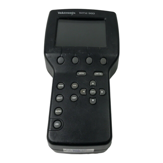
Functional Overview This section describes the WFM90D and WFM91D controls and connectors. Keypad Controls The keypad (front panel) is illustrated in Figure 2- - 1. Power Switch The ON button toggles the instrument power on and off. The current instrument keypad and menu selections are saved when you turn off the instrument using this button. -
Page 36: Figure 2- 1: Wfm90D Keypad
Functional Overview Figure 2- 1: WFM90D keypad WFM90D and WFM91D User Manual 2- 2... -
Page 37: Menu Control
The four unlabeled buttons directly below the display are referred to as the bezel buttons. These buttons are used for making menu selections and are only enabled while menus are displayed on screen. WFM90D and WFM91D User Manual 2- 3... -
Page 38: Arrow Buttons
If this reset does not return the instrument to normal operation, contact your Tektronix field office or call Tektronix at the phone number listed on page x at the front of this manual. WFM90D and WFM91D User Manual... -
Page 39: Side-Panel Connectors And Switches
Functional Overview Side-Panel Connectors and Switches The WFM90D and WFM91D side panels are illustrated in Figure 2- - 2. Video Input and Output Connectors Passive BNC input, unterminated, 75 Ω compensated for VIDEO IN. a video signal. A rear-panel switch provides an internal 75 Ω signal termination. -
Page 40: Figure 2- 2: Wfm90D And Wfm91D Side Panels
DC source is a negative-ground 11 - - 18 V system with a negative center lead. The DC source should be able to provide 12 W of power. DC IN 11-18V Figure 2- 2: WFM90D and WFM91D side panels WFM90D and WFM91D User Manual 2- 6... -
Page 41: Onscreen Readouts
Functional Overview Onscreen Readouts The WFM90D and WFM91D use onscreen messages to alert you to certain monitoring conditions. Figure 2- - 3 shows example readout messages and their locations. DIGITAL GREEN EDH CHK >CABLE NO SYNC GAIN UNCAL EXT REF... - Page 42 Waveform-in-Picture display modes when the Variable Gain is on. 11. The MISSING SYNC message appears in all analog video display modes when the signal reference has been lost. NO SYNC appears in digital modes when analog sync is missing. WFM90D and WFM91D User Manual 2- 8...
-
Page 43: Table 2- 1: Video Readout Messages
Message Conditions INPUT CTRL setting DIGITAL Digital video locked to DIGITAL or AUTO 525 on a WFM90D; 625 on a WFM91D <name of video standard> Digital video lock to an DIGITAL or AUTO unsupported standard ANALOG No digital video lock... - Page 44 Functional Overview WFM90D and WFM91D User Manual 2- 10...
-
Page 45: Operating Information
Operating Information This section contains information about the different functions of the WFM90D and WFM91D. For information about using the menus to access these functions, refer to Using the Menus on page 2- - 23. Amplitude Alarm Mode The Amplitude Alarm mode provides a means for automatic monitoring of the signal amplitude for the Waveform and Audio displays. -
Page 46: Battery Or Ac Adapter Operation
>CABLE indicates that the cable between the signal source and the WFM90D or WFM91D is approximately 200 meters or longer. If the cable is shorter than 200 meters, there is no message. NOTE. The CABLE RPT is only available when the instrument is operating in DIGITAL mode. -
Page 47: Calibration Mode
The instructions for adjusting the instrument to specifications are located in the WFM90D and WFM91D Handheld Waveform, Vector, Picture, & Audio Monitor Service Manual. CRC Watch... - Page 48 You can turn the CRC Watch on and off through any of the digital operating menus except Audio. When the CRC Watch is turned on, the WFM90D and WFM91D counts and reports all seconds containing at least one error (errored seconds).
-
Page 49: Display
EDH (Error Detection and Handling) detects CRC errors. When EDH reporting is on, and an appropriate digital signal is applied, the WFM90D or WFM91D reports EDH status in the upper-right corner of the display. You can turn the EDH report on and off through any of the digital operating menus except Audio. -
Page 50: Input/Output
You can switch the input control through the INPUT CTL category of the Configuration menu: select AUTO, DIGITAL, or ANALOG. H When the input control is set to ANALOG, the WFM90D or WFM91D operates like an analog only monitor. H When the input control is set to AUTO, the WFM90D or WFM91D operates in either analog or digital mode, depending on the input signal. -
Page 51: Line Select Mode
In addition, there is a menu selection that sets the front panel and menu settings back to a factory-set default. These default settings are listed in Table 2- - 8 on page 2- - 36. WFM90D and WFM91D User Manual 2- 17... -
Page 52: Time-Out Mode
The variable gain adjustment tracks between the Waveform and Vector display modes, and can be adjusted from the Waveform-in- Picture display mode. When the Variable Gain mode is enabled, the message GAIN UNCAL is displayed in the onscreen readout. WFM90D and WFM91D User Manual 2- 18... -
Page 53: Vector Display Mode
Figure 3- - 4 on page 3- - 5). You can turn setup on (see SETUP CTL in the Configuration Menu, page 2- - 32, or see page 2- - 46 of the Tutorial). WFM90D and WFM91D User Manual 2- 19... -
Page 54: Waveform Display Mode
You can also select a composite display, which is the digital signal converted to analog. This composite display has burst and sync. NOTE. Sync seen on the Y component is a result of the conversion process for displaying digital signals on this monitor. WFM90D and WFM91D User Manual 2- 20... -
Page 55: Waveform-In-Picture Display Mode
When viewing a digital signal, you can open the digital WIF menu (shown in Figure 2- - 5 on page 2- - 24) and turn the EDH reporting and CRC Watch on and off. WFM90D and WFM91D User Manual 2- 21... - Page 56 Operating Information WFM90D and WFM91D User Manual 2- 22...
-
Page 57: Using The Menus
CRC WTCH — OFF/ON ANALOG GAIN — X1 /X5 VECT + MENU EDH RPRT — OFF/ON DIGITAL* CRC WTCH — OFF/ON *Hold MENU button two seconds for digital menu Figure 2- 4: Waveform and Vector menus WFM90D and WFM91D User Manual 2- 23... -
Page 58: Figure 2- - 5: Audio, Picture, And Waveform-In-Picture
Using the Menus REFERENCE dBm — MIC/- - 10/0/4/8 AUDIO + MENU HEADROOM — 3 dB/10 dB ACTION — OFF/ON (WFM90D only) TITLE — OFF/ON (WFM90D only) ANALOG SAFE AREA — OFF/ON (WFM91D only) V SHIFT — OFF/ON PIX + MENU EDH RPRT —... -
Page 59: Operating Menus
Press the bezel button that corresponds to the desired selection on the display. When you make a selection, changes are displayed immediately. To adjust values, press the two right bezel buttons while displaying a menu selection such as WFM90D and WFM91D User Manual 2- 25... -
Page 60: Waveform Menu
Waveform and Vector modes. CRC WTCH Enables or disables the CRC reporting readout on the right side of the display in Waveform and Vector modes. WFM90D and WFM91D User Manual 2- 26... -
Page 61: Vector Menu
Waveform and Vector modes. CRC Watch. Enable or disable the CRC reporting CRC WTCH readout on the right side of the display in Waveform and Vector modes. WFM90D and WFM91D User Manual 2- 27... -
Page 62: Audio Menu
MIC level is for testing microphones HEADROOM Sets the headroom reference level to --3 dB or +10 dB. Use the +10 dB setting for viewing signal levels greater than 3 dB over the reference level. WFM90D and WFM91D User Manual 2- 28... -
Page 63: Picture Menu
Function ACTION WFM90D only. Turns the Safe Action area markers on and off. TITLE WFM90D only. Turns the Safe Title area markers on and off. SAFE AREA WFM91D only. Turns the Safe Area markers on and off. V SHIFT Turns the vertical shift on and off. -
Page 64: Wip Menu (Waveform-In-Picture)
Waveform and Vector modes. CRC Watch. Enable or disable the CRC reporting CRC WTCH readout on the right side of the display in Waveform and Vector modes. WFM90D and WFM91D User Manual 2- 30... -
Page 65: Configuration Menu
NOTE. If you adjust picture hue and/or color, the only way to ensure that the hue and color have been correctly reset is to recall the factory default settings through Configuration PRESETS. WFM90D and WFM91D User Manual 2- 31... -
Page 66: Figure 2- 7: Configuration Menu
DISABLED/2 MIN/5 MIN TIME-OUT SHUTDOWN DISABLED/5 MIN/10 MIN ALARMS OFF/ON PRESETS STORE/RECALL/DEFAULT CABLE RPT OFF/ON SETUP CTL OFF/ON INPUT CTL AUTO/DIGITAL/ANALOG *Must be in PIX mode to adjust Figure 2- 7: Configuration menu WFM90D and WFM91D User Manual 2- 32... -
Page 67: Table 2- 7: Configure Menu Choices
The right two bezel buttons will now adjust the signal gain. To see the category list, press the left bezel button. When the variable gain is on, GAIN UNCAL displays onscreen in Waveform, Vector, and Waveform-in-Picture display modes. WFM90D and WFM91D User Manual 2- 33... - Page 68 Vector display modes. PRESETS STORE Stores the current keypad and menu settings in memory for future recall. RECALL Resets the keypad and menu settings to the last settings that were stored in memory. WFM90D and WFM91D User Manual 2- 34...
- Page 69 There is no message If the cable is equal to or less than 200 meters. SETUP (WFM90D only; has no effect on the WFM91D) Turns the setup on or off for digital signals. When setup is on, 7.5 IRE of setup is applied to the composite display of the input signal.
-
Page 70: Table 2- 8: Default Instrument Settings
3 dB WIP location Bottom right Alarms Safe action Safe title Vertical shift Backlight time-out Disabled Instrument time-out Disabled Cable report Setup control (WFM90D function only) Input control Auto EDH report CRC watch WFM90D and WFM91D User Manual 2- 36... -
Page 71: Line Select Menu
FIELDS 1 OF 2 When 1 OF 2 is selected, the menu selection ALT FIELD appears. This allows you to select the video field in which the selected line is displayed. WFM90D and WFM91D User Manual 2- 37... - Page 72 Using the Menus WFM90D and WFM91D User Manual 2- 38...
-
Page 73: Tutorial
If you discover improper instrument operation, check the operation of associated equipment. If the associated equipment is operating normally, refer the WFM90D or WFM91D to qualified service personnel for repair or adjustment. For more information about any of the functions described here, check Operating Information, starting on page 2- - 11, or the Index at the back of the manual. -
Page 74: Initial Equipment Connections
For example: 3-foot cable (Switchcraft part no. SC3XXJ) Initial Equipment Connections H Connect power to the WFM90D or WFM91D by plugging in the AC power adapter or by installing batteries. H Connect a 75% color bar signal (with setup for NTSC) of the correct standard for your instrument from the analog television signal source to the VIDEO IN connector. -
Page 75: Adjusting The Display
Use the buttons to view the entire signal. b. Select X1 and return the signal to the graticule baseline. The gain setting affects both the Waveform and Vector displays since they track together. WFM90D and WFM91D User Manual 2- 41... - Page 76 EXT; the EXT REF readout appears onscreen. b. Remove the cable from the EXT REF input and notice that the waveform free-runs; the message MISSING SYNC appears onscreen. c. Return the reference selection to INT. WFM90D and WFM91D User Manual 2- 42...
- Page 77 The up and down arrows appear in the bar over the two right bezel buttons, signifying that they are assigned to adjust the signal gain. To restore the menu category list, press the left bezel button or turn off the variable gain. WFM90D and WFM91D User Manual 2- 43...
- Page 78 Turn off the variable gain and press the CONFIG button to exit the Configuration menu. 24. Turn setup on/off (WFM90D, Digital signal, Composite only): When viewing a digital signal in composite mode, you can turn setup on and off. When you turn setup on, the monitor will add 7.5 mV of setup to the signal on the composite display.
- Page 79 2- - 14. b. Leave the CRC WTCH selection on or off, as desired. (The default is off). 30. Provide a 75% color bar output (NTSC or PAL) from the analog television signal source. WFM90D and WFM91D User Manual 2- 45...
-
Page 80: Using The Vectorscope
Select 75% color bars output from the signal source and return the menu setting to 75% BARS. 34. Turn setup on/off (WFM90D only): a. Analog signal: Enter the Configuration menu, select the VECTOR category, and then select SETUP NO. This means that the monitor will “expect”... - Page 81 These functions provide the same readouts as in the Waveform mode (see page 2- - 45). 38. From the analog signal source, return to an NTSC/PAL color bar signal with setup. WFM90D and WFM91D User Manual 2- 47...
-
Page 82: Using The Picture Monitor
41. Select the Picture display mode. Press the MENU button to enter the Picture operating menu. 42. WFM90D only. Select ACTION ON and notice that the Safe Action area is outlined on the display. Select TITLE ON and notice that the Safe Title area is now also outlined. - Page 83 These functions provide the same readouts as in the Waveform mode (see page 2- - 45). 46. From the analog television signal source, provide an analog NTSC/PAL color bar signal with setup. WFM90D and WFM91D User Manual 2- 49...
-
Page 84: Using The Waveform-In-Picture (Wip) Display
These functions provide the same readouts as in the Waveform mode (see page 2- - 45). 52. From the signal source, return to an analog NTSC/PAL color bar signal with setup. WFM90D and WFM91D User Manual 2- 50... -
Page 85: Using The Audio Monitor
Using the Audio Monitor 53. Connect the output of the audio source to the AUDIO IN connector on the WFM90D or WFM91D. 54. Set the source for a 0 dB tone output. 55. Press the AUDIO button to select the Audio display mode. -
Page 86: Using The Amplitude Alarm
67. Return to the PRESETS category and select RECALL. Notice that the instrument returns to the WIP display mode with the Waveform display mode displayed and the Amplitude Alarm on, which was the instrument setting when you selected STORE. WFM90D and WFM91D User Manual 2- 52... -
Page 87: Using The Time-Out Mode
(5 MIN or 10 MIN). If you enable timed shutdown, after the instrument times out, press the ON button to turn it back on. This concludes the tutorial. WFM90D and WFM91D User Manual 2- 53... - Page 88 Tutorial WFM90D and WFM91D User Manual 2- 54...
-
Page 91: Reference
Reference This section explains how to take measurements with the WFM90D and WFM91D. Waveform Graticule There are two versions of the Waveform display mode graticule, illustrated in Figure 3- - 1 and Figure 3- - 2: H NTSC/525 composite video graticule (WFM90D only) -
Page 92: Horizontal Scale
+120 IRE, in 10 IRE increments. Black level setup is denoted by a dashed line at 7.5 IRE. The PAL graticule is scaled in volts and extends from 0 to 1.2 V, in 0.1 V increments. WFM90D and WFM91D User Manual 3- 2... -
Page 93: Making Waveform Measurements
The back porch portion of the input signal is used as the clamping point. NOTE. When using the shuttle mode on VCRs, set the WFM90D or WFM91D DC restorer speed to SLOW to prevent the loss of signal synchronization. -
Page 94: Vector Graticule
(radial dimension of amplitude). The two versions of the vector graticule are illustrated in Figure 3- - 3 and Figure 3- - 4: H NTSC composite vector graticule (WFM90D only) H PAL composite vector graticule (WFM91D only) Magenta Chrominance gain and... -
Page 95: Chrominance Vector Targets
Differential Phase and Gain Measurement Box Differential gain (dG) and differential phase (dφ) measurements use the graticule markings located at the outer edge of the B-Y or U axis 180° line. See Figure 3- - 6. WFM90D and WFM91D User Manual 3- 5... -
Page 96: Figure 3- - 5: Vector Targets - - Ntsc Values
Reference ° ° ° ° ° ° ° ° Figure 3- 5: Vector targets - NTSC values (PAL values in parentheses) φ φ 2° Figure 3- 6: Differential gain and phase measurement box WFM90D and WFM91D User Manual 3- 6... -
Page 97: Making Vector Measurements
This calibration aid makes it possible to check the - - 3 dB points of the demodulator output amplifiers. Digital Video When the WFM90D or WFM91D input control is set to auto or digital, you can monitor component video (525/625 component 270 Mbit serial digital video). -
Page 98: Stress Testing
You can use the EDH report or the CRC watch to monitor the occurrence of errors. As an example, using 8281 coax, a 5 meter change in length could go from no errors in one minute to more than one error per second. WFM90D and WFM91D User Manual 3- 8... -
Page 99: Audio Graticule
- - 3dB - - 3dB 0 dBu Figure 3- 7: Audio graticule with - 3 dB headroom selected +10dB 0 dBu 0 dBu +10dB Figure 3- 8: Audio graticule with +10 dB headroom selected WFM90D and WFM91D User Manual 3- 9... -
Page 100: Making Audio Measurements
Signal Amplitude Signal amplitude is checked by setting the WFM90D and WFM91D reference level through the Operating menu to match your system requirements. The amplitude of the signal display should reach the reference level graticule line during normal operation. -
Page 103: Appendix A: Specifications
Equipment Required List. Reference Information. Information that amplifies a performance requirement or is of special importance is indicated by . There is no need to check these items to a specific tolerance. WFM90D and WFM91D User Manual A- 1... -
Page 104: Electrical Characteristics
Low Pass Filter: ≥40 dB attenuation at 3.58 MHz NTSC, 4.43 MHz PAL. REF: Response at 15 kHz does not vary be- tween FLAT and LUM (low pass) filters by more than 1%. WFM90D and WFM91D User Manual A- 2... - Page 105 400 mV for X5 Gain. REQ: Position Range: 1 V signal can be positioned so that peak white and sync tip can be placed at blanking level, with the DC RESTORER on, regardless of gain set- ting. WFM90D and WFM91D User Manual A- 3...
- Page 106 Field Rate Tilt: ≤1%. REF: Line Rate Tilt: ≤1%. REF: Overscan: ≤2% variation in baseline of 100 IRE REQ: (700 mV) 12.5T (20T) modulated pulse as it is positioned over the middle 80% of the screen. WFM90D and WFM91D User Manual A- 4...
- Page 107 Within 1% with a 140 IRE (1.0 V PAL) unit (50% APL) display. Analog input only. REF: Video Out Differential Phase Within 1° with a 140 IRE (1.0 V PAL) unit display. Analog input only. (50% APL) WFM90D and WFM91D User Manual A- 5...
- Page 108 0.5 dB from 50 Hz to 20 kHz. REF: Maximum Input Level Amplitude +18 dBu. ≥15 kΩ. DC Input Impedance REF: REF: Audio Output Connector Mini stereo headphone jack. REF: Maximum Power Output 250 mW. WFM90D and WFM91D User Manual A- 6...
- Page 109 Measured between the 10 s and 110 s points on the 10 s/division (2LINE) sweep. REF: Horizontal Position Any portion of a synchronized video sweep can be positioned on-screen in all sweep modes. WFM90D and WFM91D User Manual A- 7...
- Page 110 50 Hz of F . Range PAL: 10 Hz of F . REF: Subcarrier Regenerator free-runs in ab- sence of appropriate signal. Reference can be burst of either displayed signal or exter- nal reference signal. WFM90D and WFM91D User Manual A- 8...
- Page 111 Composite video or black burst with sync ampli- tudes 40 IRE (300 mV PAL) 6 dB. Digital Input: 270 Mbit (259M). REQ: External Reference: Sync amplitude between 143 mV and 4 V will synchronize sweeps. WFM90D and WFM91D User Manual A- 9...
- Page 112 Fast Charge: 550 mA. (NiMH only) REF: Slow Charge: 150 mA. REF: Power Consumption Picture Mode: 7 Watts. Waveform Mode 9 Watts. Vector Mode 9 Watts. REQ: External Power DC Source of 11 -- 18 Volts. WFM90D and WFM91D User Manual A- 10...
-
Page 113: Physical Characteristics
10--55--10 Hz in 1-min- ute cycles with instrument secured to vibra- tion platform. Ten minutes each axis at any resonant point or at 55 Hz if no resonant point is found. WFM90D and WFM91D User Manual A- 11... - Page 114 100 g’s, 1/2 sine, 11 ms duration, 3 shocks per surface (18 total). REF: Transportation Qualified under NTSC Test Procedure 1A, Category II (24-inch drop). REF: Humidity Will operate at 95% relative humidity for up to five days. WFM90D and WFM91D User Manual A- 12...
-
Page 115: Certification
Electrical Fast Transient/Burst Immunity, Performance Criterion “B” IEC 61000-4-5 Power Line Surge Immunity, Performance Criterion “B” IEC 61000-4-6 Conducted RF Immunity , Performance Criterion “A” IEC 61000-4-11 Voltage Dips and Short Interruptions Immunity, Performance Criterion “B” WFM90D and WFM91D User Manual A- 13... - Page 116 Refer to the EMC specification published for the stated products. May not meet the intent of the directive if used with other products. Equipment Type Test and measuring Safety Class Class 3 (as defined in IEC 61010-1, Annex H) WFM90D and WFM91D User Manual A- 14...
- Page 117 Typical outdoor locations. Compliance demonstrated using high quality, shielded interface cables. Minimum immunity test requirement, except where noted. Performance Criterion: Product continues to operate properly and display remains readable. Controlled EM environment requirement (1V/M). WFM90D and WFM91D User Manual A- 15...
- Page 118 Appendix A: Specifications WFM90D and WFM91D User Manual A- 16...
-
Page 119: Appendix B: User Service
Tektronix for service. Packaging directions for shipment are on page 1- - 15. Fuse Replacement The WFM90D and WFM91D do not have any user replaceable fuses. Battery Replacement Instructions for installing or replacing the batteries along with battery operation tips are listed starting on page 1- - 7. -
Page 120: Display
Instrument Adjustment The WFM90D and WFM91D can be adjusted entirely from the front panel after entering the Calibration menu. The instrument should only be adjusted by qualified personnel. The service manual contains the instructions for adjusting the instrument. - Page 123 75%/100% amplitude distinction and either white level may be associated with either type of bars. Because of setup, the 75% signal level for NTSC is at 77 IRE. The maximum available signal amplitude is 100 IRE. Glossary- - 1 WFM90D and WFM91D User Manual...
- Page 124 Method for recognizing inaccuracies in the serial digital signal. It may be incorporated into serial digital equipment and employ a simple error indicator. A second of data transmission containing at least one error. Glossary- - 2 WFM90D and WFM91D User Manual...
- Page 125 This is the only signal required for black and white pictures. For color systems, it is obtained as a weighted sum (Y = 0.3R + 0.59G + 0.11B) of the R, G, and B signals. Glossary- - 3 WFM90D and WFM91D User Manual...
- Page 126 Synchronizing information appears between fields and tells the picture monitor to go back to the top of the screen to begin another vertical scan. Abbreviation for luminance. Glossary- - 4 WFM90D and WFM91D User Manual...
- Page 129 PICTURE category, 2- - 34 PRESETS category, 2- - 34, 2- - 35 TIME-OUT category, 2- - 34 VAR GAIN category, 2- - 33 VECTOR category, 2- - 34 Backlight time-out, 2- - 18 WFM90D and WFM91D User Manual Index- 1...
- Page 130 Electrical installation, 1- - 7 mechanical, 1- - 11 batteries (alkaline), 1- - 10 travel case, 1- - 13 battery (NiMH), 1- - 8 viewing hood, 1- - 11 Error reporting, 2- - 15 WFM90D and WFM91D User Manual Index- 2...
- Page 131 Measurements, 3- - 1 ref, 2- - 33 reference dBu, 2- - 28 audio, 3- - 10 safe area, 2- - 29 audio amplitude, 3- - 10 chroma bandwidth, 3- - 7 setup, 2- - 34 WFM90D and WFM91D User Manual Index- 3...
- Page 132 Power source, 1- - 7 Tektronix, contacting, x Power switch, 2- - 1 Time- - out mode, 2- - 18 PR (readout), 2- - 7 Time-out mode, 2- - 18 Preset menu, 2- - 17 WFM90D and WFM91D User Manual Index- 4...
- Page 133 Vector operating menu, 2- - 27 URL, Tektronix, x Vertical gain, 2- - 26, 2- - 27 User service, B- - 1 Video and audio input, 2- - 16 Video and Audio Output, 2- - 16 WFM90D and WFM91D User Manual Index- 5...
- Page 134 WIP display mode, 2- - 21 WIP operating menu, 2- - 30 Waveform display mode, 2- - 20 Waveform graticule, 3- - 1 Y (readout), 2- - 7 Waveform operating menu, 2- - 26 WFM90D and WFM91D User Manual Index- 6...
Need help?
Do you have a question about the WFM90D and is the answer not in the manual?
Questions and answers