Table of Contents
Advertisement
Quick Links
Download this manual
See also:
Service Manual
Advertisement
Table of Contents

Related Manuals for Tektronix WFM601


Summary of Contents for Tektronix WFM601
-
Page 1: User Manual
User Manual WFM601 Serial Digital Component Monitor 070-8471-00 Please check for change information at the rear of this manual. This document supports software versions 1.0 through 1.3. First Printing June 1993 Revised March 1994... - Page 2 U.S. and foreign patents, issued and pending. The following are registered trademarks: TEKTRONIX, TEK, TEKPROBE, and SCOPE MOBILE. Printed in U.S.A. For further information, contact: Tektronix, Inc., Corporate Offices, P .O. Box 1000, Wilsonville OR 97070-1000, USA. Phone: (503) 627-7111; TLX: 192825; TWX: (910) 467-8708; Cable: TEKWSGT.
- Page 3 In order to obtain service under this warranty, Customer must notify Tektronix of the defect before the expi- ration of the warranty period and make suitable arrangements for the performance of service. Customer shall be responsible for packaging and shipping the defective product to the service center designated by Tektronix, with shipping charges prepaid.
- Page 5 The German Postal Service was notified that the equipment is being marketed. The German Postal Service has the right to re test the series and to verify that it complies. TEKTRONIX Bescheinigung des Herstellers/Importeurs Hiermit wird bescheinigt, daß der/die/das WFM 601 Serial Component Monitor und alle fabrikinstallierten Optionen in Übereinstimmung mit den Bestimmungen der...
- Page 6 CURSOR LIN SEL –.1 –.2 PRESET –.3 SERIAL CONFIG COMPONENT ANALOG 2% & 4% K SERIAL A EDH DET SERIAL B ALARM GAIN VERT POS HORIZ POS CLEAR MENU POWER STANDBY WFM601 Serial Digital Component Monitor WFM601 Serial Component Monitor...
-
Page 7: Getting Started
........C–1 WFM601 Serial Component Monitor... -
Page 8: Table Of Contents
........... WFM601 Serial Component Monitor... -
Page 9: List Of Figures
Figure 1-7: Considerations for custom installation of an instrument..1–11 Figure 1-8: Channel 1 of the SMPTE color bar signal on the WFM601. 1–15 Figure 1-9: Parade display of Y and PB...... - Page 10 Figure 3-9: Construction of the Diamond GBR display....3–13 Figure 3-10: Typical bowtie display as seen on the Tektronix WFM601. 3–14 Figure B-1: Rear view of the rear-panel REMOTE connector.
- Page 11 ......... A–10 Table B 1: Remote Connector Pin Assignments and Functions ......WFM601 Serial Component Monitor...
- Page 12 Contents WFM601 Serial Component Monitor...
-
Page 13: Safety Summary
DANGER indicates a personal injury hazard immediately accessible as one reads the mark ing. This symbol appears in manuals: Static-Sensitive De- vices These symbols appear on equipment: DANGER Protective ground ATTENTION High Voltage (earth) terminal Refer to manual WFM601 Serial Component Monitor... -
Page 14: Power Source
Do Not Service Alone Do not perform internal service or adjustment of this product unless another person capable of rendering first aid and resuscitation is present. viii WFM601 Serial Component Monitor... -
Page 15: Manual Overview
Preface This manual is a guide for operators of the WFM601 monitors, and contains instructions for daily use. Please complete and mail the “Business Reply Card” at the front of this manual to receive a service manual when it becomes available. - Page 16 Preface WFM601 Serial Component Monitor...
- Page 17 Getting Started...
-
Page 19: Product Description
(follows A/B switching). gamut error bright H EDH: (Follows A/B switching) LED for presence and an alarm, rear panel TTL low through Remote Connector. H Reclocked Serial Component Digital output following A/B switching. Rev Mar 1994 1–1 WFM601 Serial Component Monitor... -
Page 20: More Information
H A complete listing of instrument specifications begins on Appendix page A-1. Options Power cord options are the only options currently available. Field upgrade kits listed in this section can also be used with these the . monitor. WFM601 1–2 WFM601 Serial Component Monitor... -
Page 21: Accessories
Cable assembly, power: all other countries (161–0066–XX) 75W End–line Terminations, 26 dB to 300 MHz (011–0163–00) Fuse, cartridge: 3AG, 2A, 250V, fast–blow (159–0021–00) Light bulbs: graticule scale (150–0168–00). Air filters: fan ( 378–0335–00 This accessory is installed on the product: 1–3 WFM601 Serial Component Monitor... -
Page 22: Field Upgrade Kits
Ordering — These items can be ordered with the monitor, or purchased through a Tektronix field office or distributor. When ordering, include both the name and number of the Field Upgrade Kits. -
Page 23: Installation
Installation Packaging At installation time, save the shipping carton and packing materials (including anti-static bag) in case it becomes necessary to ship the instrument to a Tektronix Service Center for service or repair. Repackaging for Shipment If it becomes necessary to ship the instrument to a Tektronix Service Center for service or repair, follow these instructions for repackaging: 1. -
Page 24: Figure 1-1: Dimensions Of The 1700F00 Plain Cabinet
The cabinets available for this instrument not only provide necessary shielding, and protection against accidental electrical shock, but also provide internal circuitry with protection against build up of dust. A supply of filtered, cooling Rev Mar 1994 1–6 WFM601 Serial Component Monitor... -
Page 25: Figure 1-2: 1700F02 Portable Cabinet
The 1700F02 Portable carrying case is an enhanced version of this cabinet, as is the 1700F04 side-by-side rack mount assembly. All of these cabinets are available from Tektronix. If you need one of these cabinets, contact your nearest Tektronix field office or representative for assistance in ordering. -
Page 26: Figure 1-3: Rear View Of The Instrument, Showing The Securing Screws
Rack Adapter The optional 1700F05 side-by-side rack adapter, shown in Figure 1-4, consists of two attached cabinets. It can be used to mount the WFM601 and another half-rack width instrument, such as an analog component monitor (Tektronix WFM300A or 1760–Series), in a standard 19-inch rack. -
Page 27: Figure 1-4: The 1700F05 Side-By-Side Rack Adaptor
The rack adapter is adjustable, so the WFM 601 can be more closely aligned with other equipment in the rack. See Figure 1-4. 1700F05 1700F06 Figure 1-5: Instrument in a 1700F05 with a blank front-panel (1700F06). 1–9 WFM601 Serial Component Monitor... - Page 28 If only one side of the rack adapter is used, a 1700F06 Blank Panel can be inserted in the unused section. See Figure 1-5. The rack adapter and panel are available through your local Tektronix field office or representative. When only one instrument is mounted in the side-by-side adaptor an accessory drawer (1700F07) can be installed in the blank side of the cabinet.
-
Page 29: Figure 1-7: Considerations For Custom Installation Of An Instrument
Installation To mount the WFM601 safely, attach it to a shelf strong enough to hold its weight. Install the mounting screws through the four 0.156-inch diameter holes in the bottom of the 1700F00 cabinet. See Figure 1-7. For Flush Front Panel: Cut hole... - Page 30 The rear-panel RS232 connector is a 9-pin subminiature D-type connector that provides a serial interface for remote control. The RS232 pin assignments are given in Appendix B. Operational Changes No operational modifications are made to this monitor through internal jumper settings. 1–12 WFM601 Serial Component Monitor...
-
Page 31: Required Equipment
If performing the Operator’s Familiarization Procedure reveals improper operation or instrument malfunction, first check the operation of the associated equipment. If it is operating normally but the WFM601 is not, then refer the instrument to qualified service personnel for repair or adjustment. -
Page 32: Initial Equipment Connections
Functional Check For example: A Tektronix SG505 Option 02 Oscillator installed in a Tektronix TM500 Series Power Module. In addition, an adaptor for the 25-pin miniature D-type connector will be needed to access the analog audio input. See equipment list in Section 6 (Performance Verification) for details. -
Page 33: Figure 1-8: Channel 1 Of The Smpte Color Bar Signal On The Wfm601
COMPONENT ANALOG 2% & 4% K Figure 1-8: Channel 1 of the SMPTE color bar signal on the WFM601. Press the top front-panel bezel button to select READOUT. One of the front- panel control knobs now controls the readout intensity. Adjust the control to the desired level. -
Page 34: Figure 1-9: Parade Display Of Y And Pb
Functional Check 3. Parade Display The WFM601 can display the signals on any of the components of the rear-pan- el INPUT channels simultaneously in a parade mode. To display the INPUT signals in a paraded display, press the PARADE button. Check that he PA- RADE indicator lights. -
Page 35: Figure 1-10: Parade Display Of Y, Pb, And Pr
(center assignable control) to get a display similar to the one shown in Figure 1-11. Push the LIN SEL button twice to exit the line select operating mode. Push the CONFIG button and select YPBPR for WFM AS. Push the CLEAR MENU button. 1–17 WFM601 Serial Component Monitor... -
Page 36: Figure 1-11: Wfm601 On Screen Rgb Display
Figure 1-11: WFM601 on screen RGB display. 5. Check Gain The WFM601 has an internal calibration signal which can be used to check the vertical and horizontal calibration. To display the calibration signal, press the CONFIG button to enter the configure menu. Select CALIBRATE by turning the front-panel control knob under the list of configuration categories until CALIBRATE is highlighted. -
Page 37: Figure 1-12: Wfm601 Calibrator Display
–.3 COMPONENT ANALOG 2% & 4% K Figure 1-12: WFM601 calibrator display. Note that the amplitude is 700 mV. 6. Auto Gain Calibrate The WFM601 has an auto horizontal and vertical gain calibration. Push the appropriate bezel button returns the gain to its last calibrated level. To access GAIN CAL push the bottom front panel bezel button and observe that the cursor box now surrounds the ON readout. -
Page 38: Figure 1-13: Calibrator Signal, Gain Cal On, And Both Gains Misadjusted
The LINE/FIELD button cycles the waveform sweep rate through 1 LINE (5 ms/div), 2 LINE (10 ms/div), 1 FIELD, and 2 FIELD. The MAG button provides additional line sweep rates of 200 ns/div and 1 ms/div. The FIELD sweeps magnified by approximately 25X. 1–20 WFM601 Serial Component Monitor... -
Page 39: Figure 1-14: One Field Display Of Ch 1 (Y) Signal
Check that the display changes to 2 FIELD. See 1-15. Press the LINE/FIELD button twice to return to the 2 LINE (10 ms/Div) display. 100% –.1 –.2 –.3 COMPONENT ANALOG 2% & 4% K Figure 1-15: Two field display of CH 1 (Y) signal. 1–21 WFM601 Serial Component Monitor... -
Page 40: Figure 1-16: Two Line Magnified Display
Figure 1-16: Two Line Magnified Display. 9. Flat or Differentiated Filter Selection The WFM601 offers a selection of either unfiltered display (FLAT) or differ- entiate step filter for the waveform display. The normal display is unfiltered. Press the FILTER button to enter the filter menu. Check that FLAT is high- lighted. -
Page 41: Figure 1-17: A Two-Line Differentiated Step Display
Figure 1-17: A two–line differentiated step display. 10. Line Select The WFM601 can display one line out of two fields, one line in both fields or up to 15 continuous lines in either or both fields. Display can be 1 line, 2 lines, 1 field, or 2 fields. -
Page 42: Figure 1-18: Two Field Line Select Display With Line Number 150 Selected
FIELD menu selection. Press the front-panel bezel button adjacent to NEXT FIELD. Note that the intensified zone has moved to the second field display and that the readout now reads F2 :150/ F2:164 for 525/2:1, or F2:463/F2:477 for 625/2:1. Rev Mar 1994 1–24 WFM601 Serial Component Monitor... -
Page 43: Figure 1-20: Vector Color Bar Display With Electronic Graticule
2 LINE (10 ms/Div) sweep. 11. Vector Display The WFM601 vector display uses an electronic graticule. Amplification of the vertical and horizontal axes for both the signal and the graticule are the same, which eliminates errors due to crt geometry anomalies. -
Page 44: Figure 1-21: Picture Monitor Display Of The Smpte Color Bar Signal
See pages 1-4 and 1–5 for remote connector pin assign- ments and the operational description. Press the AUDIO button to select AUDIO. The AUDIO indicator lights and the display changes to the lissajous waveform. See Figure 1-22. 1–26 WFM601 Serial Component Monitor... -
Page 45: Figure 1-22: Audio Display With Small Phase Error
Press the VECTOR/LIGHTNING button to select LIGHTNING. Check that the LIGHTNING indicator lights and that the display changes to the LIGHTNING display. See Figure 1-23. Figure 1-23: Lightning display of the component color difference signals. 1–27 WFM601 Serial Component Monitor... -
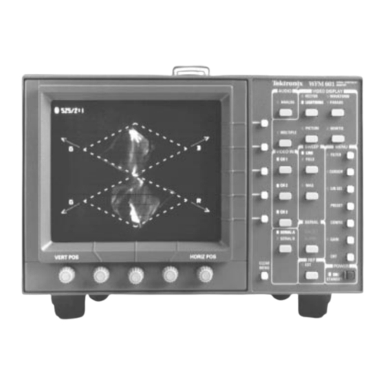
Page 46: Figure 1-24: Diamond Display
(500 kHz) signal with markers. Press the BOWTIE VIDEO DISPLAY button. Check that the BOWTIE indica- tor lights and the display changes to the BOWTIE display. See Figure 1-25. Figure 1-25: The bowtie display. 1–28 WFM601 Serial Component Monitor... - Page 47 Operating Basics...
-
Page 49: Figure 2-1: Front Panel For The Wfm601 Serial Component Monitor
MENU POWER STANDBY Figure 2-1: Front panel for the WFM601 Serial Component Monitor. Front Panel Controls and Indicators Front panel controls operate in conjunction with crt readout. The central three controls, located beneath the crt, are assigned by front panel switching. See Figure 2-1. - Page 50 AUDIO — Displays an XY plot of stereo audio channel phasing from the rear panel REMOTE connector. VIDEO IN — Turns on or off CH 1, CH 2, or CH 3 or any combination. At least one channel will always remain on. Rev Mar 1994 2–2 WFM601 Serial Component Monitor...
-
Page 51: Rear Panel Connectors
(the neutral conductor). Only the line conductor is fused for over current protection. Mains frequency is 50 or 60 Hz. Operating voltage range is continuous from 90 to 250 Vac. 2–3 WFM601 Serial Component Monitor... -
Page 52: Figure 2-2: Rear Panel For The Wfm601 Monitor
At A Glance WARNING. Do not connect power to the WFM601 if it is not enclosed in a prescribed cabinet. Dangerous potentials are present on the Power circuit board. Loop–Through Inputs Rear panel connectors are shown in Figure 2-2. SER A — Passive loop-through serial digital component input, compensated for 75W. - Page 53 Multi–pin Connectors RS232 — A 9-pin subminiature D-type connector that provides a serial interface for calibration. REMOTE — A 25-pin subminiature D-type connector that provides limited remote control functions, an alarm output, and analog audio input. 2–5 WFM601 Serial Component Monitor...
- Page 54 At A Glance 2–6 WFM601 Serial Component Monitor...
-
Page 55: Functional Overview
Audio amplitude and phase is monitored using a calibrated X/Y Lissajous display. The operator can verify that the program audio will be properly reproduced on both monaural and stereo receivers. Correct phasing between two audio channels is quickly verified by the direction of the display. 2–7 WFM601 Serial Component Monitor... -
Page 56: Displaying A Signal
Either of the two rear panel serial loop through inputs can be displayed. In the Waveform display mode, multiple channels (CH-1, CH-2, & CH-3) selected the display is overlayed. Only one serial digital conponent signal can be displayed at a time. 2–8 WFM601 Serial Component Monitor... -
Page 57: Using The Menus
One field or two field magnified = approximately X20 magnification. Using the Menus The operation of the WFM601 is under microprocessor control, which provides it with more flexibility. Operating selections that once were made by jumper changes, Digital In-line–Package (DIP) switches, or multi–position front panel switches can now be made with assignable controls and momentary push button contact switches. -
Page 58: Figure 2-4: Elements Of The Wfm601 Menu Driven Selections
TROL FUNCTIONALLY SELECTION.) ASSIGNED.) Figure 2-4: Elements of the WFM601 menu driven selections. Enabled menu selections are surrounded by a rectangle to indicate that they are active. Pressing the CLEAR MENU switch turns off the menu readout while leaving the functions that were set up by that menu. - Page 59 The first line in the display corresponds with the readout and the first line of the three displayed. The second is the from the next line and finally the last third of the display is from the third line in the sequence. See Figure 2-5. 2–11 WFM601 Serial Component Monitor...
- Page 60 RECALL – Sets the front panel to the stored settings previously loaded into that memory location. STORE – Wipes out the currently stored settings, in the selected memory location, and replaces them with the current front panel settings. 2–12 WFM601 Serial Component Monitor...
- Page 61 COLOR BARS – Scales the vector, and lightning signal amplitudes to be read on the graticule. Readout is provided to identify whether the signal is 100% or 75% amplitude color bars. DISPLAY – Provides a choice of either Lightning or Diamond display when LIGHTNING is selected. 2–13 WFM601 Serial Component Monitor...
-
Page 62: Table 2-1: Edh Crt Error Reporting
RESET ERR - If there are errored second reports a reset readout appears above the display on the CRT face. Counters for the errored seconds status are reset to 0 when the bezel push button next to the CRT readout label is pushed. 2–14 WFM601 Serial Component Monitor... -
Page 63: Figure 2-6: Parade Display With Eav/Sav Turned On
MONITOR OUT – Alarm/off enables or disables blinking on monitor out to indicate the presence of gamut errors. PANEL LED – Alarm/off enables or disables blinking of the WFM601 front panel ALARM led to indicate the presence of gamut errors. - Page 64 READOUT – On/off turns the readout off to enable the calibrator waveform to be viewed without extraneous detail. Pushing the same bezel button, when readout is off, brings back the menu. Readout automatically returns when exiting the CALIBRATE mode. 2–16 WFM601 Serial Component Monitor...
-
Page 65: Remote Operation
TTL low or ground closure is the enabling level. The user can store and recall up to eight front-panel setups through the remote. Remote connector pin assignments and an operational description are in Appendix B. 2–17 WFM601 Serial Component Monitor... - Page 66 Functional Overview Using Presets through the The WFM601 has 10 presets capable of storing front-panel setups. Presets one REMOTE Remote through eight are accessible through the rear-panel connector. A TTL PRESET low or ground closure on one of the pins selects the front-panel setup stored at that preset location.
- Page 67 Reference...
-
Page 69: Figure 3-1: Wfm601 Waveform Measurement Graticule
Making A Measurement Making a measurement contains WFM601 graticule descriptions, followed by specific measurement procedures. This monitor uses an internal graticule, which combines waveform and vector markings. The internal graticule scales are on the same plane as the CRT phosphor, eliminating parallax errors. Graticule illumination can be adjusted... - Page 70 When the sweep button is set to 1 line, each major division represents 5 microseconds (ms), minor divisions equal 1 ms; when set to 2 line sweep, each major division represents 10 ms, minor divisions equal 2 ms. Rev Mar 1994 3–2 WFM601 Serial Component Monitor...
-
Page 71: Figure 3-2: Wfm601 Vectorscope Graticule
75% (or 100%) amplitude for the color being measured. Figure 3-2: WFM601 vectorscope graticule. On the WFM601 electronic component vectorscope graticule, each chrominance vector terminates in a target See Figure 3-2. The dimension of each target box equals 2% of the 700 mV, or 14 mV. -
Page 72: Figure 3-3: Electronic Graticule Used For Evaluating The Lightning Display
Errors in green amplitude affect both diamonds equally, while blue amplitude errors affect only the top diamond and red errors affect only the bottom diamond. See Figure 3-4. 3–4 WFM601 Serial Component Monitor... -
Page 73: Figure 3-4: Graticule For The Diamond Display
(up to 90 ) is a relative measure of the phase difference. At 90 the display is a circle; errors greater than 90 cause the axis to rotate by 90 . 3–5 WFM601 Serial Component Monitor... -
Page 74: Figure 3-5: Electronic Graticule For Measurement Of Stereo Audio Phase
Making A Measurement Figure 3-5: Electronic graticule for measurement of stereo audio phase. The electronic graticule for the WFM601 has scales for measurement of stereo audio phase. The dashed diagonal line is the measurement axis for errors less than 90 , it is terminated in amplitude targets that correspond to the length of X and Y axes. -
Page 75: Adjusting Instrument Gain
If the RESET H CAL readout is on, push the adjacent bezel button. c. Pushing RESET H CAL reinstates the gain setting established at the last calibration. d. Check to see that there is one half cycle/division (1–line sweep) or one cycle/division (2–line sweep). 3–7 WFM601 Serial Component Monitor... - Page 76 Calibration This page intentionally blank. 3–8 WFM601 Serial Component Monitor...
-
Page 77: Measurement Theory
The purpose of any test equipment is to locate and identify abnormal operation. The role of the WFM601 is no different. It is designed to work in a relatively new technology, and to do so it incorporates some displays that are not in common use. -
Page 78: Lightning Display
B–Y OR U Figure 3-6: Vector display relationship of the R–Y (V) and B–Y (U). The electronic graticule for the WFM601 provides vector targets that are $2% of B–Y and R–Y amplitudes. This differs from composite vectorscope targets, which are sectors indicating a polar, magnitude and phase error. These are the errors most often caused by the coding, transmission and decoding of the composite signal. -
Page 79: Figure 3-7: Construction Of The Lightning Waveform
(bending of the green/magenta transitions). Figure 3-8 shows the graticule and the measure- ment targets and timing delay scales. Figure 3-8: The lightning graticule demonstrating interchannel timing errors. 3–11 WFM601 Serial Component Monitor... -
Page 80: Diamond Display
Any signal outside the gamut limits, scribed by the graticule, may not be reproducible by a color monitor, or is subject to clipping. This robust system of 3–12 WFM601 Serial Component Monitor... -
Page 81: Bowtie Display
A special test signal is required for this display. The Tektronix TSG-422, Option 1S provides this type of signal and a set of time marks to aid in signal evaluation. The signal is a 500 kHz sinewave on channel 1 (luminance) and 502 kHz sinewave on channels 2 and 3 (color difference signals). -
Page 82: Figure 3-10: Typical Bowtie Display As Seen On The Tektronix Wfm601
The time markers are from the generator and are 20 ns apart. Figure 3-10: Typical bowtie display as seen on the Tektronix WFM601. The bowtie test signal and display method provides better resolution and is easier to use than the waveform or lightning display when with color bar test signal to make relative channel timing measurements. - Page 83 Appendices...
-
Page 85: Appendix A: Specification
Appendix A Specification Appendix A: Specification The items listed in the following tables describe the performance of the WFM601 Serial Digital Component Monitor. Performance Requirements are generally quantitative and can be tested by the Performance Verification Procedure, contained in the Service Manual. -
Page 86: Table A-1: Waveform Vertical Deflection
X1, X5, or X10 with any variable gain setting. REF: $0.5% REQ: Voltage Cursor Accuracy Amplitude of pulses v5% variation. Differentiated Step Filter REF: REF: Field Rate Tilt Line Rate Tilt REF: Rev Mar 1994 A–2 WFM601 Serial Component Monitor... -
Page 87: Table A-2: Serial Digital Interface (Serial A & Serial B)
270 Mbit/s component. Complies with SMPTE 259M & CCIR 656. 800 mV peak–to–peak $10% . REQ: Output Level Internal jumper can change output to 740 mV peak–to–peak$10% . REF: w15 dB 1–270 MHz. REQ: Return Loss Rev Mar 1994 A–3 WFM601 Serial Component Monitor... -
Page 88: Table A-4: Serial Video Diagnostics (Edh)
–8.5V to +8.5V, dc plus peak ac. Absolute Maximum Input Voltage w20 kW. DC Input Impedance REF: w40 dB to 6 MHz. REQ: Return Loss Typically w46 dB to 6 MHz; w40 dB to 10 MHz. REF: Rev Mar 1994 A–4 WFM601 Serial Component Monitor... -
Page 89: Table A-6: Waveform Horizontal Deflection
Table A-7: Calibrator Amplitude: 0.700V $1% REQ: Waveform Squarewave Frequency: 100 kHz $0.1% REQ: Crystal controlled outputs a 10 ms squarewave that can be used for REF: adjusting horizontal gain of the instrument. Rev Mar 1994 A–5 WFM601 Serial Component Monitor... -
Page 90: Table A-8: Analog Audio Mode
Display to Graticule Registration No visible gaps or tails at corners of target boxes. Electronic Graticule Shape REF: Vector Display REF: is displayed on horizontal axis and P is displayed on vertical axis. Rev Mar 1994 A–6 WFM601 Serial Component Monitor... -
Page 91: Table A-10: Lightning Mode
EBU/N10. Input Format REF: 700 mV $3% REQ: Active Video Accuracy REF: Typically <1% 300 mV $10% REF: Sync Amplitude Accuracy Nominally 75W. Back porch clamped to 0V. Monitor Output Impedance REF: Rev Mar 1994 A–7 WFM601 Serial Component Monitor... -
Page 92: Table A-13: Power Source
Nominally 13.75 kV. Accelerating Potential REF: REQ: Greater that + & – 1 from horizontal. Trace Rotation Range Total adjustment range is typically w8 . REF: REF: Internal with variable illumination. Graticule Rev Mar 1994 A–8 WFM601 Serial Component Monitor... -
Page 93: Table A-15: Environmental Characteristics
Pollution Degree IEC 1010–1 Level 2 operating environment REQ: Will operate at 95% relative humidity for up to five days. Humidity Do not operate with visible moisture on the circuit boards. REF: Rev Mar 1994 A–9 WFM601 Serial Component Monitor... -
Page 94: Table A-16: Certification
FCC EMI Compatibility (FCC Rules Part 15, Subpart J, Class A) VDE 0871.5 (Class B) Instrument must be installed in a cabinet equal to the shielding provided by Tektronix F00 or F02 cabinets to qualify for EMI certification. Table A-17: Physical Characteristics... -
Page 95: Table B 1: Remote Connector Pin Assignments And Functions
Table B-1: Remote Connector Pin Assignments and Functions Name Function/Description Not used. Ground Not used. Low= Blank External Blanking Input. Ground Ground Ground Max. Input $8 V peak. (Measured to +Y Audio (Left) Chassis Ground.) B–1 WFM601 Serial Component Monitor... - Page 96 Preset 6 memory location to store the current front panel settings. Ground (TTL low) Recalls the stored front PRESET 7 panel setup from this location, or selects the Preset 7 memory location to store the current front panel settings. B–2 WFM601 Serial Component Monitor...
-
Page 97: Rs232 Connector
RS232 Connector The RS232 connector is a 9–pin D–type connector that is provided as the calibration interface. See Figure B-2. The WFM601 is intended to be calibrated with a Personal Computer (PC). See Section 6 for more information. DATA... - Page 98 Appendix B: Multipin Connectors B–4 WFM601 Serial Component Monitor...
-
Page 99: Cleaning Or Replacing The Fan Filter
The line fuse for this instrument is located inside the cabinet, under a protective shield. Replacement of this fuse should only be undertaken by a qualified service technician, following the instructions in the WFM601 Service Manual. Graticule Light Replacement Replacement Bulbs Replacement bulbs are supplied with this instrument as Standard Accessories. -
Page 100: Figure C-1: Graticule Light Replacement
6. Replace the five knobs below the CRT and tighten the set screws. Recess Recess Remove this panel (shaded portion) Remove these five knobs Figure C-1: Graticule light replacement. Rev Mar 1994 C–2 WFM601 Serial Component Monitor... -
Page 101: Cleaning
Cleaning of rosin residue is not recommended. Most cleaning solvents tend to reactivate the rosin and spread it under components where it may cause corrosion under humid conditions. The rosin residue, if left alone, does not exhibit these corrosive properties. C–3 WFM601 Serial Component Monitor... -
Page 102: Replacing The Crt Filter
7. Replace the panel below the CRT, and press on both the right and left sides of the panel until it snaps into place. 8. Replace the five knobs below the CRT and tighten the set screws. Rev Mar 1994 C–4 WFM601 Serial Component Monitor... -
Page 103: Appendix D: Software Version
The software version number for this instrument is displayed on the Calibrate sub menu of the Configure Menu. The version number is located in the lower right corner of the CRT display. In addition, a second number is also displayed which identifies the Coprocessor code. WFM601 Serial Component Monitor... - Page 104 Appendix D: Software Version WFM601 Serial Component Monitor...
- Page 105 Glossary and Index...
- Page 107 Broad Pulses Another name for the vertical synchronizing pulses in the center of the vertical interval. These pulses are long enough to be distinguished from all others, and are the part of the signal actually detected by vertical sync separators. Glossary–1 WFM601 Serial Component Monitor...
- Page 108 R–Y and B–Y to the luminance signal for NTSC systems or U and V to the luminance signal for PAL systems. CW Continuous Wave. Refers to a separate subcarrier sine wave used for synchronization of chrominance information. Glossary–2 WFM601 Serial Component Monitor...
- Page 109 In television it may refer to: (1) An instrument, such as a TEKTRONIX 1450, which takes video in its transmitted form (modulated onto the picture carrier) and converts it to baseband.
- Page 110 1 volt. The 0 IRE point is at blanking level, with sync tip at –40 IRE and white extending to +100 IRE. IRE stands for Institute of Radio Engineers, the organization which defined the unit. Glossary–4 WFM601 Serial Component Monitor...
- Page 111 Quadrature distortion appears when envelope detection is used, but can be eliminated by using a synchronous demodulator. RF Radio Frequency. In television applications, RF generally refers to the television signal after the picture carrier modulation process Glossary–5 WFM601 Serial Component Monitor...
- Page 112 U The B–Y signal after a weighting factor of 0.493 has been applied. The weighting is necessary to reduce peak modulation in the composite signal. Glossary–6 WFM601 Serial Component Monitor...
- Page 113 Waveform Monitor A specialized oscilloscope that plots voltage versus time to evaluate television signals. Y Abbreviation for luminance. Zero Carrier Reference A pulse in the vertical interval which is produced by the demodulator to provide a reference for evaluating depth of modulation. Glossary–7 WFM601 Serial Component Monitor...
- Page 114 Glossary Glossary–8 WFM601 Serial Component Monitor...
- Page 115 Fan filter, part number, 1–4 the CRT, C–3 Field upgrade kits, 1–4 the instrument, C–3 Filter Menu, 2–10 Cleaning Fan Filter, C–1 Format, Standard, Color Bars, Display, WFM As, Mon CLEAR MENU, 2–3 Out As, 2–13 Index–1 WFM601 Serial Component Monitor...
- Page 116 Operating voltage, 1–12 Optional accessories, 1–4 Options, 1–3 Ordering Field Upgrade Kits, 1–4 Inputs, Displaying a Signal, 2–8 Outputs, MON OUT, (Y/G - PB/B - PR/R), 2–5 Installation Overlay, Displaying a Signal, 2–9 electrical, 1–11 Index–2 WFM601 Serial Component Monitor...
- Page 117 Waveform Horizontal Deflection, Specification, A–5 Resetting Vertical Gain, 3–7 Waveform Vertical Deflection, Specification, A–2 RS232, Multi-pin Connectors, 2–5 WFM AS (RGB or Y-PB-PR), 2–14 RS232 Connector, B–3 Y/G-PB/B-PR/R, Monitor Out, 2–5 Serial A Input, Loop–Through Inputs, 2–4 Index–3 WFM601 Serial Component Monitor...
- Page 118 Index Index–4 WFM601 Serial Component Monitor...
Need help?
Do you have a question about the WFM601 and is the answer not in the manual?
Questions and answers