Table of Contents
Advertisement
Quick Links
Service Manual
WFM90D and WFM91D
Handheld Waveform, Vector,
Picture, and Audio Monitor
071-1143-00
This document applies to firmware version 2.13
and above.
Warning
The servicing instructions are for use by qualified
personnel only. To avoid personal injury, do not
perform any servicing unless you are qualified to
do so. Refer to all safety summaries prior to
performing service.
www.tektronix.com
Advertisement
Table of Contents
Troubleshooting

Related Manuals for Tektronix WFM90D


Summary of Contents for Tektronix WFM90D
- Page 1 Service Manual WFM90D and WFM91D Handheld Waveform, Vector, Picture, and Audio Monitor 071-1143-00 This document applies to firmware version 2.13 and above. Warning The servicing instructions are for use by qualified personnel only. To avoid personal injury, do not perform any servicing unless you are qualified to do so.
- Page 2 Copyright © Tektronix, Inc. All rights reserved. Tektronix products are covered by U.S. and foreign patents, issued and pending. Information in this publication supercedes that in all previously published material. Specifications and price change privileges reserved. Tektronix, Inc., P.O. Box 500, Beaverton, OR 97077...
- Page 3 Tektronix, with shipping charges prepaid. Tektronix shall pay for the return of the product to Customer if the shipment is to a location within the country in which the Tektronix service center is located. Customer shall be responsible for paying all shipping charges, duties, taxes, and any other charges for products returned to any other locations.
- Page 5 ..........4- - 3 Performance Verification: Analog Section ..... 4- -5 WFM90D and WFM91D Service Manual...
-
Page 6: Table Of Contents
..........6- - 51 WFM90D and WFM91D Service Manual... - Page 7 ..........9- -1 WFM90D and WFM91D Service Manual...
- Page 8 ....... 2- -8 Figure 2- -7: WFM90D and WFM91D side panels ....
- Page 9 Figure 9- -1: Interconnect diagram ......9- -1 WFM90D and WFM91D Service Manual...
- Page 10 Table 7- -3: Optional accessories ......7- -2 WFM90D and WFM91D Service Manual...
- Page 11 If you suspect there is damage to this product, Do Not Operate With Suspected Failures. have it inspected by qualified service personnel. Do Not Operate in Wet/Damp Conditions. Do Not Operate in an Explosive Atmosphere. Keep Product Surfaces Clean and Dry. WFM90D and WFM91D Service Manual...
- Page 12 This product contains a Nickel battery, which must be recycled or disposed of properly. For the location of a local battery recycler in the U.S. or Canada, please contact: RBRC (800) BATTERY Rechargeable Battery Recycling Corp. (800) 227-7379 P.O. Box 141870 www.rbrc.com Gainesville, Florida 32614 viii WFM90D and WFM91D Service Manual...
- Page 13 Use Care When Servicing With Power On. Dangerous voltages or currents may exist in this product. Disconnect power, remove battery (if applicable), and disconnect test leads before removing protective panels, soldering, or replacing components. To avoid electric shock, do not touch exposed connections. WFM90D and WFM91D Service Manual...
- Page 14 Service Safety Summary WFM90D and WFM91D Service Manual...
- Page 15 Preface This manual provides instructions for servicing the WFM90D and WFM91D Handheld Waveform, Vector, Picture, and Audio Monitors. This manual describes features and specifications that are common to all generator modules. These include system configuration and the common control interface.
- Page 16 This phone number is toll free in North America. After office hours, please leave a voice mail message. Outside North America, contact a Tektronix sales office or distributor; see the Tektronix web site for a list of offices. WFM90D and WFM91D Service Manual...
- Page 17 Specifications...
- Page 19 H Selectable time out for backlight or instrument power H Signal level alarm mode for waveform and audio displays H Preset menu to store/recall front panel and menu setups H Instrument adjustments from front panel (see service manual) 1- 1 WFM90D and WFM91D Service Manual...
-
Page 20: Table 1- 1: Vertical Deflection System
REF: Low Pass Filter: ≥40 dB attenuation at 3.58 MHz NTSC, 4.43 MHz PAL. REF: Response at 15 kHz does not vary between FLAT and LUM (low pass) filters by more than 1%. 1- 2 WFM90D and WFM91D Service Manual... - Page 21 Field Rate Tilt: ≤1%. REF: Line Rate Tilt: ≤1%. REF: Overscan: ≤2% variation in baseline of 100 IRE (700 mV) 12.5T (20T) modulated pulse as it is REQ: positioned over the middle 80% of the screen. 1- 3 WFM90D and WFM91D Service Manual...
-
Page 22: Table 1- 2: Dc Restoration
90% will cause blanking level shift of 1 IRE unit (7.14 mV PAL) or less. REF: Blanking Level Shift Due to Presence or Absence of Burst: 1 IRE unit (7.14 mV PAL) or less shift from no color burst to presence of color burst. 1- 4 WFM90D and WFM91D Service Manual... -
Page 23: Table 1- 3: Audio Mode
Measured between the 10 s and 110 s points on the 10 s/division (2LINE) sweep. REF: Horizontal Position Any portion of a synchronized video sweep can be positioned on-screen in all sweep modes. 1- 5 WFM90D and WFM91D Service Manual... -
Page 24: Table 1- 5: Vector Mode
Variable Gain Control REF: Subcarrier Regenerator Phase 360° continuous rotation. Control Range REF: Subcarrier Regenerator Burst Jitter 0.5° RMS or less. REF: With 140 IRE (1 V) composite video input. INT or EXT referenced. 1- 6 WFM90D and WFM91D Service Manual... -
Page 25: Table 1- 6: Synchronization
12 VDC plus peak AC. Table 1- 7: Power source Category Description REF: Battery 6 C-cell batteries or Tektronix NiMH battery pack (Tektronix Part No. 146-0107-01). REF: Battery Charge Time Fast Charge: 550 mA. REF: Slow Charge: 150 mA. REF: Power Consumption Picture Mode: 7 Watts. -
Page 26: Table 1- 9: Environmental Characteristics
100 g’s, 1/2 sine, 11 ms duration, 3 shocks per surface (18 total). REF: Transportation Qualified under NTSC Test Procedure 1A, Category II (24-inch drop). REF: Humidity Will operate at 95% relative humidity for up to five days. 1- 8 WFM90D and WFM91D Service Manual... -
Page 27: Table 1- 10: Certifications And Compliances
Emissions comply with FCC Code of Federal Regulations 47, Part 15, Subpart B, Class A Limits. Equipment Type Test and measuring Safety Class Class 3 (as defined in IEC 61010-1, Annex H) Pollution Degree Pollution Degree 2 (as defined in IEC 61010-1). Note: Rated for indoor use only. 1- 9 WFM90D and WFM91D Service Manual... - Page 28 The area is protected from direct sunshine, rain, or direct wind. Pollution Degree 4 Pollution that generates persistent conductivity through conductive dust, rain, or snow. Typical outdoor locations. 1- 10 WFM90D and WFM91D Service Manual...
- Page 29 Operating Information...
- Page 31 Instructions on page 6- -2 for instructions on packaging the instrument for shipment. Viewing Hood You can purchase a viewing hood and desk stand to use with your WFM90D or WFM91D. The viewing hood makes it easier to view the instrument display in well-lighted situations.
-
Page 32: Figure 2- 1: Installing The Viewing Hood
The desk stand holds the monitor upright on a flat surface. Insert the prongs of the stand into the holes in the back of the instrument as shown in Figure 2- -2. Figure 2- 2: Installing the desk stand 2- 2 WFM90D and WFM91D Service Manual... -
Page 33: Figure 2- 3: Packing The Option 33 Travel Case
3. Spare batteries for the handheld monitor. 4. Spare batteries for the handheld generator. 5. Handheld generator, desk stand, and carrying straps. 6. AC adapter(s). Figure 2- 3: Packing the Option 33 travel case 2- 3 WFM90D and WFM91D Service Manual... - Page 34 Press in on the top portion of the battery connector tab and then pull up gently. To replace the NiMH battery pack, use only the Tektronix rechargeable NiMH battery pack, part number 146- -0107- -01. Do not use any other battery pack.
-
Page 35: Figure 2- 4: Removing The Nimh Battery Pack
1/4 turn. Replace all of the batteries, following the polarity indications on the bottom of the battery compartment, which are also shown in Figure 2- -5. 2- 5 WFM90D and WFM91D Service Manual... -
Page 36: Figure 2- 5: Inside Of The Battery Compartment, Showing Polarity Markings
Installation Figure 2- 5: Inside of the battery compartment, showing polarity markings 2- 6 WFM90D and WFM91D Service Manual... - Page 37 PIX. Pressing the PIX button enters the Picture display mode. WIP. Pressing the WIP button enters the Waveform-in-Picture display mode. The previously selected display mode, other than Picture, is shown in a 1/4-screen-sized window that overlays the Picture display. 2- 7 WFM90D and WFM91D Service Manual...
-
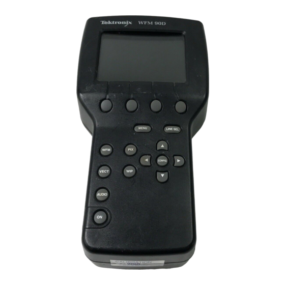
Page 38: Figure 2- 6: Wfm90D Keypad
Functional Overview WFM90D Press and hold for two seconds to open the digital menu for the selected operating mode Figure 2- 6: WFM90D keypad 2- 8 WFM90D and WFM91D Service Manual... - Page 39 The arrow buttons retain their default function for the reduced display when the Waveform-in-Picture display mode is selected. When the Configuration menu is displayed, the buttons operate the menu category selection, while the buttons retain their default function for the current display mode. " 2- 9 WFM90D and WFM91D Service Manual...
- Page 40 If this reset does not return the instrument to normal operation, contact your Tektronix field office or call Tektronix at the phone number listed on page xii at the front of this manual. Side-Panel Connectors and Switches side panels are illustrated in Figure 2- -7.
-
Page 41: Figure 2- 7: Wfm90D And Wfm91D Side Panels
11 - - 18 V system with a negative center lead. The DC source should be able to provide 12 W of power. DC IN 11-18V Figure 2- 7: WFM90D and WFM91D side panels 2- 11 WFM90D and WFM91D Service Manual... -
Page 42: Figure 2- 8: Onscreen Readout Messages
200 meters. If the cable is shorter than 200 meters, there is no readout. NOTE. The CABLE RPT readout is meaningful only when the instrument is operating in DIGITAL mode. In ANALOG mode, you can ignore the readout. 2- 12 WFM90D and WFM91D Service Manual... -
Page 43: Table 2- 1: Video Readout Messages
Message Conditions INPUT CTRL setting DIGITAL Digital video locked to 525 on a DIGITAL or AUTO WFM90D; 625 on a WFM91D <name of video standard> Digital video lock to an unsup- DIGITAL or AUTO ported standard ANALOG No digital video lock... - Page 44 Functional Overview 2- 14 WFM90D and WFM91D Service Manual...
-
Page 45: Figure 2- 9: Waveform And Vector Menus
CRC WTCH — OFF/ON ANALOG GAIN — X1 /X5 VECT + MENU EDH RPRT — OFF/ON DIGITAL* CRC WTCH — OFF/ON *Hold MENU button two seconds for digital menu Figure 2- 9: Waveform and Vector menus 2- 15 WFM90D and WFM91D Service Manual... -
Page 46: Figure 2- 10: Audio, Picture, And Waveform-In-Picture Menus
Using the Menus REFERENCE dBm — MIC/- - 10/0/4/8 AUDIO + MENU HEADROOM — 3 dB/10 dB ACTION — OFF/ON (WFM90D only) TITLE — OFF/ON (WFM90D only) ANALOG SAFE AREA — OFF/ON (WFM91D only) V SHIFT — OFF/ON PIX + MENU EDH RPRT —... - Page 47 Hold the MENU button in for two seconds to open the digital menu. For more details on menu access, see page 2- -17. Waveform menu choices are shown in Table 2- -2. The Waveform menu tree is shown in Figure 2- -9. 2- 17 WFM90D and WFM91D Service Manual...
-
Page 48: Table 2- 2: Waveform Menu Choices, Analog And Digital
Enable or disable the EDH reporting readout at the top center of the display in Waveform and Vector modes. CRC WTCH CRC Watch. Enable or disable the CRC reporting readout on the right side of the display in Waveform and Vector modes. 2- 18 WFM90D and WFM91D Service Manual... -
Page 49: Table 2- 4: Audio Menu Choices
Function ACTION WFM90D only. Turns the Safe Action area markers on and off. TITLE WFM90D only. Turns the Safe Title area markers on and off. SAFE AREA WFM91D only. Turns the Safe Area markers on and off. V SHIFT Turns the vertical shift on and off. The vertical shift allows you to view the vertical interval on the Picture display. -
Page 50: Table 2- 6: Wip Menu Choices, Analog And Digital
Enable or disable the EDH reporting readout at the top center of the display in Waveform and Vector modes. CRC WTCH CRC Watch. Enable or disable the CRC reporting readout on the right side of the display in Waveform and Vector modes. 2- 20 WFM90D and WFM91D Service Manual... - Page 51 TRACE ADJUST NOTE. If you adjust picture hue and/or color, the only way to ensure that the hue and color have been correctly reset is to recall the factory default settings through Configuration PRESETS. 2- 21 WFM90D and WFM91D Service Manual...
-
Page 52: Figure 2- 12: Configuration Menu
DISABLED/2 MIN/5 MIN TIME-OUT SHUTDOWN DISABLED/5 MIN/10 MIN ALARMS OFF/ON PRESETS STORE/RECALL/DEFAULT CABLE RPT OFF/ON SETUP CTL OFF/ON INPUT CTL AUTO/DIGITAL/ANALOG *Must be in PIX mode to adjust Figure 2- 12: Configuration menu 2- 22 WFM90D and WFM91D Service Manual... -
Page 53: Table 2- 7: Configure Menu Choices
When HUE is selected, the right two Bezel Buttons adjust the hue of the Picture display (instrument must be in Picture display mode). COLOR The right two Bezel Buttons adjust the color of the Picture display (instrument must be in Picture display mode). 2- 23 WFM90D and WFM91D Service Manual... - Page 54 >Cable if the cable length is greater than 200M. If the cable is equal to or less than 200 meters, there is no readout. (WFM90D only; has no effect on the WFM91D). SETUP Turns the setup on or off for digital signals. When setup is on, 7.5 IRE of setup is applied to the input signal.
-
Page 55: Table 2- 8: Default Instrument Settings
3 dB WIP location Bottom right Alarms Safe action Safe title Vertical shift Backlight time-out Disabled Instrument time-out Disabled Cable report Setup control (WFM90D function only) Input control Auto EDH report CRC watch 2- 25 WFM90D and WFM91D Service Manual... -
Page 56: Table 2- 9: Line Select Menu Choices
The menu bar over these two buttons displays the selected line number. FIELDS 1 OF 2 When 1OF 2 is selected, the menu selection ALT FIELDappears. This allows you to select the video field in which the selected line is displayed. 2- 26 WFM90D and WFM91D Service Manual... - Page 57 Theory of Operation...
- Page 59 CARRIER_DET line to estimate the degradation that the SDI signal has experienced due to long cables and so forth. The entire board is controlled by a I2C bus with the I2C clock on SCLK and the I2C data on MOSI. 3- 1 WFM90D and WFM91D Service Manual...
- Page 60 Top and Bottom boards. The power for the LCD Display module comes from the Bottom board, while the power for the backlight comes from the Backlight Power Supply board. The display backlight mounts into the side of the LCD Display module. 3- 2 WFM90D and WFM91D Service Manual...
-
Page 61: Figure 3- 1: Simplified Block Diagram
P/O Top Board Subcarrier Control DAC Oscillator (16 analog Outputs) Backlight Power Supply Board Sync Separator Timing Part of P Display Brightness and Backlight View Adjust Timing Brightness Figure 3- 1: Simplified block diagram 3- 3 WFM90D and WFM91D Service Manual... - Page 62 Theory of Operation 3- 4 WFM90D and WFM91D Service Manual...
- Page 63 Performance Verification...
- Page 65 The verification procedures are written in a sequential format. If you are unsure about equipment hookups or instrument settings for a specific procedure step, you will need to review the previous steps to verify the hookups and settings required for the current step. 4- 1 WFM90D and WFM91D Service Manual...
-
Page 66: Table 4- 1: Summary Verification Procedure
50 kHz. X5 Gain Response (Flat filter selected): 50 kHz to 6 MHz within 5% of response at 50 kHz. Attenuation of 60 Hz (50 Hz PAL) on Input Signal: SLOW mode: ≤20%. FAST mode: ≥90%. 4- 2 WFM90D and WFM91D Service Manual... -
Page 67: Table 4- 2: Equipment Required For Performance Verification
Leveled sine wave generator Output Level Range: - - 11.55 dBm (200 mV) to Tektronix SG 503 Leveled Sine Wave Generator 0.43 dBm (800 mV); Frequency: 50 kHz to 10 MHz 4- 3 WFM90D and WFM91D Service Manual... - Page 68 (AA and AB). The TSG3 and TSG13 are Modulated Staircase Generators with variable APL. The TSG5 and TSG15 are Pulse and Bar Generators with modulated pulse and field square wave signals. Requires a Tektronix TM 500-Series or TM 5000-Series Power Module Mainframe. 4- 4...
-
Page 69: Sync Separation
2. Connect the multiburst signal from the analog television signal generator through a 75 Ω in-line terminator and dual-input coupler to the VIDEO IN and REF IN connectors on the WFM90D or WFM91D monitor. 3. Set the input termination switches to the HIZ position. -
Page 70: Sweep Timing And Integral Linearity
3%. Integral Linearity: 1. Connect the multiburst signal from the analog television signal generator to the VIDEO IN connector on the WFM90D or WFM91D monitor, and to the input on the frequency counter, using a T-connector, 75 Ω cable, and 75 Ω... -
Page 71: Vertical Gain And Vertical Magnifier Registration
Range: 1 V signal can be positioned so that peak white and sync tip can be placed at blanking level, with the DC Restorer Clamp on, regardless of gain setting. 1. Set the VAC for a 999.9 mV output. 4- 7 WFM90D and WFM91D Service Manual... -
Page 72: Overscan
2% while using the Vertical Position controls to position the signal over the middle 80% of the graticule. 2. Remove the pulse and bar signal from the VIDEO IN connector. 4- 8 WFM90D and WFM91D Service Manual... -
Page 73: Input And Dc Restorer Frequency Response
14. Check that the digital multimeter readout level or the oscilloscope DC level, is within 14 mV of the reading noted in step 8. 15. Set the sine wave generator frequency to 50 kHz. 16. Select X5 GAIN from the Operating menu. 4- 9 WFM90D and WFM91D Service Manual... - Page 74 EXT REF and SLOW DC REST. 31. Set the function generator to output a 60 Hz (50 Hz PAL) sine wave with a display amplitude of 100 IRE (700 mV PAL) on the WFM90D or WFM91D monitor. 32. Connect a black burst signal to the REF IN connector. Do not terminate the input.
-
Page 75: Vector Phase Stability
1. Connect a 75% color bar signal to the VIDEO IN connector. Set the input switch to the 75 Ω position. 2. Select VECTOR display mode on the WFM90D or WFM91D monitor. 3. Use the Phase controls to position the burst vector on the 180° graticule line. -
Page 76: Chrominance Bandwidth
- -3 dB (70%) point gaps on the horizontal graticule axis. 7. Check that the frequency readout on the leveled sine wave generator is between 2.98 and 3.18 MHz (3.83 and 4.03 MHz PAL). 4- 12 WFM90D and WFM91D Service Manual... -
Page 77: Audio Gain And Frequency Response
2. Set the audio generator for a 1 kHz tone output, with an amplitude of +8.0 dBu. Select Signal On. 3. Select AUDIO display mode on the WFM90D or WFM91D monitor. 4. Enter the Operating menu and select 8 dBu. - Page 78 23. Check that the display amplitude is within 0.5 dB of the reference level graticule lines. 24. Set the audio generator frequency to 20 kHz. 25. Check that the display amplitude is within 0.5 dB of the reference level graticule lines. 4- 14 WFM90D and WFM91D Service Manual...
-
Page 79: Performance Verification: Digital Section
Performance Verification: Digital Section Perform the following steps before beginning the verification procedures: 1. Plug the AC power adapter into the WFM90D or WFM91D monitor and then plug the adapter into the AC power source. 2. Connect the 75% color bar signal from the digital television signal generator to the VIDEO IN connector on the WFM90D or WFM91D monitor. -
Page 80: Check Frequency Response
Flat Filter, 1 V Full Scale, 50 kHz to 4.5 MHz, within 4% 1. Enter the Configure menu. Select PRESETS and then select DEFAULT. 2. Select the WFM display mode on the WFM90D or WFM91D monitor. 3. Press MENU to display the waveform menu. -
Page 81: Check Frequency Response At X5 Gain
This procedure verifies the following requirement: Flat Filter, X5 Gain, 50 kHz to 4.5 MHz, within 5%. 1. Select the WFM mode on the WFM90D or WFM91D monitor. 2. Press MENU to display the waveform menu. 3. Set the GAIN to X5 and exit the menu. - Page 82 Performance Verification: Digital Section 4- 18 WFM90D and WFM91D Service Manual...
-
Page 83: Adjustment Procedures
Adjustment Procedures... -
Page 85: Adjustments
5- - 10 DIGITAL SECTION: Preliminary setup 5- - 11 Vertical gain 5- - 11 Frequency response 5- - 12 Vector gain and X5 gain phase 5- - 12 Cable margin 5- - 13 5- 1 WFM90D and WFM91D Service Manual... -
Page 86: Equipment Required
Frequency: 100 MHz BNC female to BNC female Tektronix part number 103-0028-00 connector BNC female to dual banana Tektronix part number 103-0090-00 adapter Requires a Tektronix TM 500-Series or TM 5000-Series Power Module Mainframe. 5- 2 WFM90D and WFM91D Service Manual... -
Page 87: Adjustment Procedures
Conventions Throughout these procedures, boldface type indicates that you will use a front-panel control or select a specific menu item on the WFM90D or WFM91D. Prerequisites The adjustments in this section provide a valid adjustment of instrument... - Page 88 Adjustments 5- 4 WFM90D and WFM91D Service Manual...
-
Page 89: Adjustment Procedures: Analog Section
Adjustment Procedures: Analog Section Perform these steps to prepare the instrument to be adjusted: 1. Plug the AC power adapter into the WFM90D or WFM91D, and then plug the adapter into the AC power source. 2. Set the input termination switches to the HIZ position. - Page 90 27. Select MAG ON, and then select MAG REG. 28. Use the arrow buttons to return the falling edge of sync to the center graticule mark. 29. Select MAG OFF. 30. Select CAL MENU, and then select SAVE. 5- 6 WFM90D and WFM91D Service Manual...
-
Page 91: Vertical Gain And X5 Gain Registration
Perform these steps to adjust the frequency response: 1. Connect a 50 Ω precision cable from the leveled sine wave generator output to the dual-input coupler using a 50 Ω-to-75 Ω minimum loss attenuator. 5- 7 WFM90D and WFM91D Service Manual... - Page 92 18. 21. Select X5 FREQ from the Calibration menu, and then select CAL. 22. Adjust the arrow buttons for a display amplitude of exactly 100 IRE (700 mV PAL). 5- 8 WFM90D and WFM91D Service Manual...
-
Page 93: Vector Quadrature Phase
Vector Gain and X5 Gain Phase Perform these steps to adjust the vector gain and X5 gain phase: 1. WFM90D ONLY — Verify that the television signal generator has setup turned on. 2. Select VEC GAIN from the Calibration menu, select CAL, and then select TEST ON. -
Page 94: Audio Gain
2. Set the audio generator for a 1 kHz tone output with an amplitude of +8.0 dBu. Select Signal On from the audio generator. 3. Select the AUDIO display mode on the WFM90D or WFM91D. 4. Select 8 dBu from the Operating menu. -
Page 95: Adjustment Procedures: Digital Section
1. Plug the AC power adapter into the WFM90D or WFM91D, and then plug the adapter into the AC power source. 2. Set the input termination switches to the 75 Ω position on the WFM90D or WFM91D. 3. Connect a 75% color bar signal from the digital television signal generator to the VIDEO IN connector. -
Page 96: Frequency Response
4. Moving between PHASE and DG VEC GAIN, Adjust the left and right arrow buttons so that the vector dots land in the center of the graticule target boxes. See Figure 5- -1. 5. Select DG CAL MENU, and then select SAVE. 5- 12 WFM90D and WFM91D Service Manual... -
Page 97: Cable Margin
Perform the following steps to adjust the cable margin indicator (you are adjusting the value at which the cable flag comes on to 200 meters): 1. Connect the output from the digital signal generator to the WFM90D or WFM91D through the cable clone. Set the cable clone to simulate 200 me- ters of Belden 8281 cable. - Page 98 Adjustment Procedures: Digital Section 5- 14 WFM90D and WFM91D Service Manual...
-
Page 99: Maintenance
Maintenance... -
Page 101: Cleaning
The remedy for most visible defects is obvious; however, if heat-damaged parts are discovered, determine the cause of overheating before replacing the damaged part. 6- 1 WFM90D and WFM91D Service Manual... -
Page 102: After Repair Adjustments
Styrofoam kernels, overfill the box and compress the kernels by closing the lid. There should be three inches of tightly packed cushion- ing on all sides of the instrument. 3. Seal the carton with shipping tape, industrial stapler, or both. 6- 2 WFM90D and WFM91D Service Manual... -
Page 103: Remove And Replace
Remove and Replace This section tells you how to remove and replace the customer replaceable modules and parts of the WFM90D or WFM91D Handheld Waveform, Vector, Picture, and Audio Monitor. CAUTION. To prevent damage to the instrument, disconnect the power adapter and remove installed batteries from the monitor before starting disassembly. -
Page 104: Procedures
6- - 24 Turnlock stud receptacle 6- - 26 Bottom cover electrical shield 6- - 27 Battery orientation marker and battery 6- - 27 cushion pad AC adapter EMI suppressor 6- - 29 6- 4 WFM90D and WFM91D Service Manual... -
Page 105: Figure 6- 1: Removing The Top Cover
Top Cover. To remove the top cover assembly, perform the following procedure: 1. Remove the six retaining screws using the Torx-tip screwdriver. See Figure 6- -1. Remove Torx screws (6) Figure 6- 1: Removing the top cover 6- 5 WFM90D and WFM91D Service Manual... - Page 106 The LCD display assembly contains replaceable subparts. Procedures for removing the subparts are included below. CAUTION. To avoid damaging the LCD display, do not touch the face of the display because it is hard to clean and is easily scratched. 6- 6 WFM90D and WFM91D Service Manual...
-
Page 107: Figure 6- 2: Installing The Lcd Display Cable
See Figure 6- -2. Contacts Open slide latch connector to install cable. Close latch connector Contacts Figure 6- 2: Installing the LCD display cable 6- 7 WFM90D and WFM91D Service Manual... - Page 108 NOTE. Some early instruments used cushion pads instead of locating feet to hold the display module in position. If your instrument has cushion pads, replace the pads at this time with locating feet. Contact your local Tektronix representative to order the necessary parts.
-
Page 109: Figure 6- 3: Installing The Lcd Display
LCD Display Padding. To remove the LCD display padding, perform the following procedure: 1. Remove the top cover. Refer to Top Cover on page 6- -5. 2. Remove the LCD display module. Refer to LCD Display on page 6- -7. 6- 9 WFM90D and WFM91D Service Manual... - Page 110 LCD Display Padding on page 6- -9. A new display pad is supplied with the replacement backlight assembly. 4. Install the LCD display module. Refer to LCD Display on page 6- -7. 5. Install the top cover. Refer to Top Cover on page 6- -5. 6- 10 WFM90D and WFM91D Service Manual...
- Page 111 1. Press the nubs on the keypad through the holes in the Top board. 2. Use tweezers or needle-nose pliers from the backside of the Top board to pull the nubs of the keypad through the Top board. See Figure 6- -4. 6- 11 WFM90D and WFM91D Service Manual...
-
Page 112: Figure 6- 4: Installing The Keypad
3. Slide the Top board shield out from under the Top board. To replace the Top board shield, perform the following procedure: 1. If you are replacing the Top board shield, bend the tab on the shield as shown in Figure 6- -5. 6- 12 WFM90D and WFM91D Service Manual... -
Page 113: Figure 6- 5: Installing The Top Board Shield
Failure to do this will result in noisy display graphics. See Figure 6- -5. 3. Install the two retaining screws into the top of the Top board. 4. Install the top cover. Refer to Top Cover on page 6- -5. 6- 13 WFM90D and WFM91D Service Manual... - Page 114 5. Install the LCD display module. Refer to LCD Display on page 6- -7. 6. Install the top cover. Refer to Top Cover on page 6- -5. 7. Install the battery cover. Refer to Battery Cover on page 6- -18. 6- 14 WFM90D and WFM91D Service Manual...
-
Page 115: Figure 6- 6: Installing The Bottom Board
Remove and Replace Backlight board Align the Backlight and Input boards into the slots of the bottom cover Input board assembly Figure 6- 6: Installing the Bottom board 6- 15 WFM90D and WFM91D Service Manual... -
Page 116: Figure 6- 7: Installing The Sdi Interface Board
2. Align the Backlight and Input boards with the slots in the bottom cover and gently slide the boards into the bottom cover. 3. Install the Top board. Refer to Top Board on page 6- -11. 6- 16 WFM90D and WFM91D Service Manual... - Page 117 4. Gently pull the Input board assembly from the back of the Bottom board. 5. Unscrew the retaining nuts from the three BNC connectors on the rear panel. 6. Pull the rear panel cover off of the BNC connectors. 6- 17 WFM90D and WFM91D Service Manual...
- Page 118 1. Insert the two standoff studs of the carrying strap through the battery cover and install the two retaining nuts. 2. Install the battery cover. Refer to Battery Cover on page 6- -18. 6- 18 WFM90D and WFM91D Service Manual...
-
Page 119: Figure 6- 8: Installing The Battery Cover
1. Remove the battery cover. Refer to Battery Cover on page 6- -18. 2. Gently pry up on the outside portion of the bushing as shown in Figure 6- -9. 3. Gently pull and rock the turnlock stud while holding the bushing. 6- 19 WFM90D and WFM91D Service Manual... -
Page 120: Figure 6- 9: Removal And Replacement Of The Turnlock Stud
The bushing will snap into place when it is correctly installed. 3. Install the battery cover. Refer to Battery Cover on page 6- -18. 6- 20 WFM90D and WFM91D Service Manual... - Page 121 1. Press the battery connector onto the jumper in the battery compartment. Be sure the battery connector tab snaps onto the jumper housing to prevent a loss of battery power. 2. Install the battery cover. Refer to Battery Cover on page 6- -18. 6- 21 WFM90D and WFM91D Service Manual...
-
Page 122: Figure 6- 10: Removing The Nimh Battery Pack
See Figure 6- -11. NOTE. The polarity of the alkaline batteries must be correct for the instrument to operate. Always replace all of the alkaline batteries at the same time when replacing discharged batteries. 6- 22 WFM90D and WFM91D Service Manual... -
Page 123: Figure 6- 11: Installed Polarity Of Alkaline Batteries
1. Lift the Bottom board slightly out of the top cover so that you can connect the battery-power wires onto jumper J21 of the Bottom board. 2. Carefully place the bottom cover onto the top cover. 6- 23 WFM90D and WFM91D Service Manual... - Page 124 2. To remove one of the battery contacts that has the battery power connector soldered to it, unsolder the battery connector wire before you remove the battery contact. 3. Pry the battery contact past the retaining lip on the bottom cover. See Figure 6- -12. 6- 24 WFM90D and WFM91D Service Manual...
-
Page 125: Figure 6- 12: Battery Contact Installation Alignment
3. If you replaced one of the battery contacts that had the battery-power wires soldered to it, resolder the battery connector wire to the battery contact. See Figure 6- -13. 6- 25 WFM90D and WFM91D Service Manual... -
Page 126: Figure 6- 13: Battery Power-Wire And Turnlock Stud Receptacle Installation
1. Remove the bottom cover. Refer to Bottom Cover on page 6- -23. 2. Depress the retaining fingers on the turnlock stud receptacle and push the receptacle through the bottom cover. See Figure 6- -13. 6- 26 WFM90D and WFM91D Service Manual... - Page 127 4. If necessary, clean the surface of the battery cushion pad or the bottom cover to remove any remaining glue residue. Refer to Cleaning on page 6- -1. 6- 27 WFM90D and WFM91D Service Manual...
-
Page 128: Figure 6- 14: Battery Orientation Marker Position
3. Rub your fingers over the battery cushion pad once it is positioned on the bottom cover to make sure the pad is securely in place. Line up holes to aid positioning Battery orientation marker Battery cushion Figure 6- 14: Battery orientation marker position 6- 28 WFM90D and WFM91D Service Manual... -
Page 129: Figure 6- 15: Installing The Emi Suppressor
2. Loop the AC adapter cord through the middle of the EMI suppressor. Close the EMI suppressor until the sides of the suppressor latch together. See Figure 6- -15. EMI suppressor Loop the cord through once Figure 6- 15: Installing the EMI suppressor 6- 29 WFM90D and WFM91D Service Manual... - Page 130 Remove and Replace 6- 30 WFM90D and WFM91D Service Manual...
-
Page 131: Troubleshooting Procedures
Troubleshooting Procedures This section contains the following information to help you locate problems within the WFM90D or WFM91D: H List of equipment required to perform the procedures H Battery-fault analysis H Low-voltage power supply H Fault symptom table H Troubleshooting flowcharts... -
Page 132: Battery-Fault Analysis
Use the following procedure to determine if the battery charger circuit is operating properly: 1. Remove the AC adapter from the WFM90D or WFM91D. 2. Remove the battery cover and any installed batteries from the instrument. See Batteries on page 6- -21. - Page 133 1 kV can be present on the Backlight power supply leads when operated open circuit. If the LCD module is removed, always remove the Backlight board before powering up the instrument for test. 6- 33 WFM90D and WFM91D Service Manual...
-
Page 134: Low-Voltage Power Supply
Use the following procedure to check that the low-voltage power supplies are operating properly before proceeding to Fault Symptom Table. 1. Disconnect the AC adapter from the WFM90D or WFM91D. 2. Remove any installed batteries. See Batteries on page 6- -21. -
Page 135: Fault Symptom Table
Vector display jitter page 6- - 47 Distorted vectors in Vector display page 6- - 47 Control problem page 6- - 48 Menus horizontally unlocked in Picture display mode page 6- - 49 6- 35 WFM90D and WFM91D Service Manual... -
Page 136: Troubleshooting Flowcharts
Table 6- -5. Figure 6- -33 on page 6- -51 illustrates the connector and pin locations for the circuit board connectors listed in the troubleshooting flowcharts. 6- 36 WFM90D and WFM91D Service Manual... - Page 137 J20-4 = 1.25 VDC (1.25-1.75 VDC as the good? oscilloscope? Backlight brightness is changed using the CONFIGURE menu) Replace the Bottom Replace the Backlight in the board. Display module. Figure 6- 17: Flowchart for no display 6- 37 WFM90D and WFM91D Service Manual...
- Page 138 (These voltages are set in the CALIBRATION MENU.) J9-7 = 0.9 VDC J9-8 = 1.2 VDC Are the size Replace the Top board. voltages OK? Replace the Bottom board. Figure 6- 18: Flowchart for distorted waveform display 6- 38 WFM90D and WFM91D Service Manual...
- Page 139 J9-1 = 1.3 Vpp, 2.5 VDC J9-3 = 0.6 Vpp, 2.5 VDC Are the vector Replace the Bottom board. deflection signals Replace the Top board. Figure 6- 19: Flowchart for no vector display 6- 39 WFM90D and WFM91D Service Manual...
- Page 140 Check the SDI Interface board: J1-15 Replace SDI is analog video signal Interface board. (reconstructed from digital) present? Replace the input board. Figure 6- 20: Flowchart for problems processing serial digital input signals 6- 40 WFM90D and WFM91D Service Manual...
- Page 141 J9-3 = +1 V to +3.8 V ramp with a 35 ms period Are the audio deflection signals Replace the Bottom board. Replace the Top board. Figure 6- 21: Flowchart for bad audio display 6- 41 WFM90D and WFM91D Service Manual...
- Page 142 (Probe J16 from the back of the Bottom board.) J16-14 = +5 VDC in PIX mode Is the SEL_EXVIDEO Replace the Top board. signal OK? Replace the Display module. Figure 6- 22: Flowchart for no picture display 6- 42 WFM90D and WFM91D Service Manual...
- Page 143 (J9 is on the Top board.) J9-6 = Approximately 10 mVDC Is the Raster VCO Replace the Bottom board. control signal Replace the Top board. Figure 6- 23: Flowchart for bad graticules and menus 6- 43 WFM90D and WFM91D Service Manual...
- Page 144 J16-3 = (G) 0 to +1.3 V J16-4 = (R) 0 to +1.3 V all of these Replace the signals Bottom board. correct? Replace the Display module. Figure 6- 24: Flowchart for all white display 6- 44 WFM90D and WFM91D Service Manual...
- Page 145 J14-9 = 1.2 Vpp, +1.3 VDC pulses blanking level. Replace the Top board. Is the REF Replace the IN signal Input board. Replace the Bottom board. Figure 6- 25: Flowchart for untriggered waveform display 6- 45 WFM90D and WFM91D Service Manual...
- Page 146 Is the Replace the Bottom board. boards one at a time. IFsc signal Replace the Top board. Figure 6- 26: Flowchart for unlocked vector display 6- 46 WFM90D and WFM91D Service Manual...
- Page 147 J9-42 = 400 mVpp filtered square wave J9-43 = 300 mVpp filtered square wave Are the IFsc and QFsc Replace the Bottom board. signals Replace the Top board. Figure 6- 28: Flowchart for distorted vectors 6- 47 WFM90D and WFM91D Service Manual...
- Page 148 Top or Bottom boards, and can only be determined by replacing these boards one at a time. Figure 6- 29: Flowchart for problems with the instrument controls 6- 48 WFM90D and WFM91D Service Manual...
- Page 149 Are the VSYNC and HSYNC Replace the Top board. signals good and locked to the video input signal? Replace the Bottom board. Figure 6- 30: Flowchart for bad menus in the picture display 6- 49 WFM90D and WFM91D Service Manual...
- Page 150 Figure 6- 31: Flowchart for dim or blotchy display Use this procedure when all of the display modes are bad except Picture when no menus are displayed. Replace the Top board. Figure 6- 32: Flowchart for bad displays except Picture mode 6- 50 WFM90D and WFM91D Service Manual...
-
Page 151: Connector Diagram
Top board SDI Interface board J9- - 13 = +8 V J9- - 14 = - - 8 V J9- - 15 = +5 V Figure 6- 33: Circuit board connector and pin locations 6- 51 WFM90D and WFM91D Service Manual... - Page 152 Troubleshooting Procedures 6- 52 WFM90D and WFM91D Service Manual...
- Page 153 Options...
-
Page 155: Table 7- 1: Options
. You WFM90D and WFM91D can order options and accessories with the monitor or purchase them separately through a Tektronix field office or distributor. When ordering, include the option or part number and the description. Options You can order the following options with the . -
Page 156: Table 7- 2: Standard Accessories
WFM90D & WFM91D Handheld Waveform, Vector, Picture, & Audio 071-1143-00 Monitor Service Manual NiMH battery pack 146-0107-01 Instrument desk stand 386-6787-01 Viewing hood 011-0167-01 Travel case for a WFM90D or WFM91D monitor and a TSG95 or 016-1344-00 TSG601 signal generator 7- 2 WFM90D and WFM91D Service Manual... - Page 157 Replaceable Mechanical Parts...
- Page 159 For more information about the module exchange program, call 1-800-833-9200. Outside North America, contact a Tektronix sales office or distributor; see the Tektronix web site for a list of offices: www.tektronix.com. Module Repair and Return. You may ship your module to us for repair, after which we will return it to you.
- Page 160 Items in this section are referenced by figure and index numbers to the exploded view illustrations that follow. Tektronix part number Use this part number when ordering replacement parts from Tektronix. 3 and 4 Serial number Column three indicates the serial number at which the part was first effective. Column four indicates the serial number at which the part was discontinued.
- Page 161 7911 ZIONSVILLE RD INDIANAPOLIS, IN 46268 TK1416 SHARP CORP 22- - 22 NAGAIKE- - CHO OSAKA, JAPAN ABENO- - KU TK2427 A/D ELECTRONICS INC 10421 BURNHAM DRIVE NW, BLDG #4 GIG HARBOR, WA 98332 8- 3 WFM90D and WFM91D Service Manual...
- Page 162 Replaceable Parts List Figure 8- 1: Exploded view 8- 4 WFM90D and WFM91D Service Manual...
- Page 163 346- - 0279- - 00 STRAP,CARRYING:1.00 X 11.00 CARRY HANDLE 80009 346- - 0279- - 00 8- - 26 348- - 1428- - 00 PAD,CUSHIONING:MTL,0.062 THICK PORON 80009 348- - 1428- - 00 8- 5 WFM90D and WFM91D Service Manual...
- Page 164 CIRCUIT BD ASSY:TOP BOARD,WFM91D 80009 671- - 5590- - 00 8- - 40 119- - 4788- - 00 KEYPAD:ELASTOMERIC,FRONT PANEL,17 KEY 80009 119- - 4788- - 00 --41 150- - 0215- - 00 LAMP:BACKLIGHT,FLUORESCENT TK1416 LQ0B01 8- 6 WFM90D and WFM91D Service Manual...
- Page 165 386- - 6787- - 00 011- - 0167- - 01 HOOD:PLASTIC 80009 011- - 0167- - 01 016- - 1344- - 00 CARRYING CASE:WFM90D OR WFM91D & TSG95 80009 016- - 1344- - 00 119- - 4540- - 00 POWER SUPPLY:12W,12V 1.0A,UNREGULATED, 14310 D48121000A220CM 220VAC 50HZ,183CM CABLE W/5.5MM OD,...
- Page 166 Replaceable Parts List 8- 8 WFM90D and WFM91D Service Manual...
- Page 167 Diagrams...
- Page 169 Diagrams The interconnect diagram, Figure 9- -1, shows the jumpers and connectors for the WFM90D and WFM91D Handheld Waveform, Vector, Picture, and Audio Monitor. A6 SDI Interface Board A1 Input Board A2 Top Board A3 Bottom Video In Board Test only...
- Page 170 Diagrams 9- 2 WFM90D and WFM91D Service Manual...
Need help?
Do you have a question about the WFM90D and is the answer not in the manual?
Questions and answers