Sign In
Upload
Manuals
Brands
Tektronix Manuals
Monitor
WFM91D
Tektronix WFM91D Manuals
Manuals and User Guides for Tektronix WFM91D. We have
2
Tektronix WFM91D manuals available for free PDF download: Quick Start Manual, User Manual
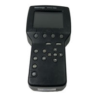
Tektronix WFM91D User Manual (134 pages)
Handheld Waveform, Vector, Picture, and Audio Monitor
Brand:
Tektronix
| Category:
Monitor
| Size: 0 MB
Table of Contents
User Manual
1
Table of Contents
5
General Safety Summary
11
Product Description 1
13
Features 1
13
Preface
13
Manual Conventions
13
Contacting Tektronix
14
Product Description
17
Features
17
Options 1
19
Options and Accessories 1
19
More Information
19
Table 1- 1: Options
21
Options and Accessories
21
Options
21
Table 1- 2: Standard Accessories
22
Table 1- 3: Optional Accessories
22
Accessories
22
Installation
23
Electrical Installation
23
Power Source
23
Recharging the Nimh Batteries
24
Figure 1- 1: Removing the Nimh Battery Pack
25
Replacing the Alkaline Batteries
26
Figure 1- 2: Inside of the Battery Compartment, Showing Polarity Markings
26
Mechanical Installation
27
Viewing Hood
27
Figure 1- 3: Installing the Viewing Hood
27
Desk Stand
28
Figure 1- 4: Installing the Desk Stand
28
Travel Case
29
Figure 1- 5: Packing the Option 33 Travel Case
29
Incoming Inspection
30
Packaging for Shipment
31
Functional Overview
35
Keypad Controls
35
Power Switch
35
Display Mode Selection
35
Figure 2- 1: WFM90D Keypad
36
Menu Control
37
Arrow Buttons
38
Instrument Reset
38
Side-Panel Connectors and Switches
39
Video Input and Output Connectors
39
Audio Input and Output Connectors
39
DC Power Input Connector
39
Figure 2- 2: WFM90D and WFM91D Side Panels
40
Onscreen Readouts
41
Readout Description
41
Figure 2- 3: Onscreen Readout Messages
41
Table 2- 1: Video Readout Messages
43
Operating Information
45
Amplitude Alarm Mode
45
Audio Display Mode
45
Battery or AC Adapter Operation
46
Cable Report
46
Instrument Adjustment
47
Calibration Mode
47
CRC Watch
47
Display
49
EDH Report
49
Input/Output
50
Line Select Mode
51
Picture Display Mode
51
Preset Menu
51
Time-Out Mode
52
Backlight Time-Out
52
Instrument Power Time-Out
52
Variable Gain Mode
52
Vector Display Mode
53
Gain
53
Video Input Control
53
Viewing Serial Digital Signals
53
Waveform Display Mode
54
Video Input Control
54
Viewing Serial Digital Signals
54
Waveform-In-Picture Display Mode
55
Video Input Control
55
Viewing Serial Digital Signals
55
Using the Menus
57
Figure 2- 4: Waveform and Vector Menus
57
Figure 2- - 5: Audio, Picture, and Waveform-In-Picture
58
Figure 2- 6: Line Select Menu
58
Operating Menus
59
Accessing Menus
59
Accessing Digital Menus
59
Using the Menus
59
Waveform Menu
60
Table 2- 2: Waveform Menu Choices, Analog and Digital
60
Vector Menu
61
Table 2- 3: Vector Menu Choices, Analog and Digital
61
Audio Menu
62
Table 2- 4: Audio Menu Choices
62
Picture Menu
63
Table 2- 5: Picture Menu Choices, Analog and Digital
63
WIP Menu (Waveform-In-Picture)
64
Table 2- 6: WIP Menu Choices, Analog and Digital
64
Configuration Menu
65
Configure Menu Access
65
Using the Menu
65
Figure 2- 7: Configuration Menu
66
Table 2- 7: Configure Menu Choices
67
Table 2- 8: Default Instrument Settings
70
Table 2- 9: Line Select Menu Choices
71
Line Select Menu
71
Tutorial
73
Required Equipment
73
Initial Equipment Connections
74
Procedure
74
Restoring Factory Default Settings
74
Adjusting the Display
75
Using the Waveform Monitor
75
Using the Vectorscope
80
Using the Picture Monitor
82
Using the Waveform-In-Picture (WIP) Display
84
Using the Audio Monitor
85
Using the Amplitude Alarm
86
Using the Presets
86
Using the Time-Out Mode
87
Reference
91
Waveform Graticule
91
Figure 3- 1: NTSC Waveform Graticule
91
Figure 3- 2: PAL Waveform Graticule
92
Horizontal Scale
92
Vertical Scales
92
Making Waveform Measurements
93
Standard Measurements
93
Peak White
93
DC Restorer
93
Vector Graticule
94
Figure 3- 3: NTSC Vector Graticule
94
Chrominance Vector Targets
95
Differential Phase and Gain Measurement Box
95
Figure 3- 4: PAL Vector Graticule
95
Figure 3- - 5: Vector Targets - - NTSC Values
96
Parentheses) 3
96
Making Vector Measurements
97
Chroma Bandwidth
97
Stress Testing
98
Audio Graticule
99
Making Audio Measurements
100
Signal Amplitude
100
Frequency Response
100
Headroom
100
Appendix A: Specifications
103
Electrical Characteristics
104
Physical Characteristics
113
Environmental Characteristics
113
Certification
115
Appendix B: User Service
119
Fuse Replacement
119
Battery Replacement
119
Cleaning and Maintenance
119
Display
120
Instrument Adjustment
120
Advertisement
Tektronix WFM91D Quick Start Manual (170 pages)
Handheld Waveform, Vector, Picture, and Audio Monitor
Brand:
Tektronix
| Category:
Measuring Instruments
| Size: 1 MB
Table of Contents
Table of Contents
6
Table 1- 1: Vertical Deflection System
20
Table 1- 2: DC Restoration
22
Table 1- 3: Audio Mode
23
Table 1- 4: Horizontal Deflection System
23
Table 1- 5: Vector Mode
24
Table 1- 6: Synchronization
25
Table 1- 7: Power Source
25
Table 1- 8: Physical Characteristics
25
Table 1- 9: Environmental Characteristics
26
Table 1- 10: Certifications and Compliances
27
Figure 2- 1: Installing the Viewing Hood
32
Figure 2- 2: Installing the Desk Stand
32
Figure 2- 3: Packing the Option 33 Travel Case
33
Figure 2- 4: Removing the Nimh Battery Pack
35
Figure 2- 5: Inside of the Battery Compartment, Showing Polarity Markings
36
Figure 2- 6: WFM90D Keypad
38
Figure 2- 7: WFM90D and WFM91D Side Panels
41
Figure 2- 8: Onscreen Readout Messages
42
Table 2- 1: Video Readout Messages
43
Figure 2- 9: Waveform and Vector Menus
45
Figure 2- 10: Audio, Picture, and Waveform-In-Picture Menus
46
Figure 2- 11: Line Select Menu
46
Table 2- 2: Waveform Menu Choices, Analog and Digital
48
Table 2- 3: Vector Menu Choices, Analog and Digital
48
Table 2- 4: Audio Menu Choices
49
Table 2- 5: Picture Menu Choices, Analog and Digital
49
Table 2- 6: WIP Menu Choices, Analog and Digital
50
Figure 2- 12: Configuration Menu
52
Table 2- 7: Configure Menu Choices
53
Table 2- 8: Default Instrument Settings
55
Table 2- 9: Line Select Menu Choices
56
Figure 3- 1: Simplified Block Diagram
61
Table 4- 1: Summary Verification Procedure
66
Table 4- 2: Equipment Required for Performance Verification
67
Sync Separation
69
Sweep Timing and Integral Linearity
70
Vertical Gain and Vertical Magnifier Registration
71
Variable Gain Range and Vertical Position Range
71
Overscan
72
Input and DC Restorer Frequency Response
73
Vector Phase Stability
75
Chrominance Bandwidth
76
Figure 4- 1: - 3 Db Marks on the Vector Graticule
76
Audio Gain and Frequency Response
77
Performance Verification: Digital Section
79
Check Sync Separation
79
Check Frequency Response
80
Check Frequency Response at X5 Gain
81
Adjustment Procedures
83
Adjustments
85
Summary Adjustment
85
Table 5- 1: Summary Adjustment
85
Equipment Required
86
Table 5- 2: Equipment Required for Adjustments
86
Adjustment Procedures
87
Adjustment Procedures: Analog Section
89
Raster VCO
89
Sweep Timing and Horizontal Mag Registration
89
Vertical Gain and X5 Gain Registration
91
Frequency Response
91
Vector Quadrature Phase
93
Vector Gain and X5 Gain Phase
93
Audio Gain
94
Figure 5- 1: NTSC Graticule Showing the Vector Gain Adjustment
94
Adjustment Procedures: Digital Section
95
Vertical Gain
95
Frequency Response
96
Vector Gain and X5 Gain Phase
96
Cable Margin
97
Maintenance
99
Cleaning
101
After Repair Adjustments
102
Repackaging Instructions
102
Remove and Replace
103
Tools Required
103
Table 6- 1: Tools Required for Module Removal
103
Procedures
104
Table 6- 2: Remove and Replace Procedure List
104
Figure 6- 1: Removing the Top Cover
105
Figure 6- 2: Installing the LCD Display Cable
107
Figure 6- 3: Installing the LCD Display
109
Figure 6- 4: Installing the Keypad
112
Figure 6- 5: Installing the Top Board Shield
113
Figure 6- 6: Installing the Bottom Board
115
Figure 6- 7: Installing the SDI Interface Board
116
Figure 6- 8: Installing the Battery Cover
119
Figure 6- 9: Removal and Replacement of the Turnlock Stud
120
Figure 6- 10: Removing the Nimh Battery Pack
122
Figure 6- 11: Installed Polarity of Alkaline Batteries
123
Figure 6- 12: Battery Contact Installation Alignment
125
Figure 6- 13: Battery Power-Wire and Turnlock Stud Receptacle Installation
126
Figure 6- 14: Battery Orientation Marker Position
128
Figure 6- 15: Installing the EMI Suppressor
129
Troubleshooting Procedures
131
Equipment Required
131
Table 6- 3: Equipment Required for Troubleshooting
131
Battery-Fault Analysis
132
Low-Voltage Power Supply
134
Table 6- 4: Low-Voltage Power Supplies
134
Fault Symptom Table
135
Table 6- 5: Fault Symptom Table
135
Troubleshooting Flowcharts
136
Connector Diagram
151
Table 7- 1: Options
155
Table 7- 2: Standard Accessories
156
Table 7- 3: Optional Accessories
156
Advertisement
Related Products
Tektronix WFM90D
Tektronix WFM700HD
Tektronix WFM700A
Tektronix WFM2200
Tektronix WFM601
Tektronix WFM7120
Tektronix WFM7100 Opt. MB
Tektronix WFM5200 series
Tektronix WFM 601i
Tektronix WFM720UP
Tektronix Categories
Test Equipment
Measuring Instruments
Amplifier
Portable Generator
Printer
More Tektronix Manuals
Login
Sign In
OR
Sign in with Facebook
Sign in with Google
Upload manual
Upload from disk
Upload from URL