Table of Contents
Advertisement
Advertisement
Table of Contents

Subscribe to Our Youtube Channel
Related Manuals for Smartgen APC715


Summary of Contents for Smartgen APC715
- Page 1 APC715 Pump Unit Controller USER MANUAL Smartgen Technology...
- Page 2 All rights reserved. No part of this publication may be reproduced in any material form (including photocopying or storing in any medium by electronic means or other) without the written permission of the copyright holder. Smartgen Technology reserves the right to change the contents of this document without prior notice.
- Page 3 Version Date Version Note 2013-08-28 Original release. This manual is suitable for APC715 pump unit controller only. Clarification of notation used within this publication. SYMBOL INSTRUCTION Highlights an essential element of a procedure to ensure NOTE correctness. Indicates a procedure or practice, which, if not strictly observed, CAUTION! could result in damage or destruction of equipment.
-
Page 4: Table Of Contents
APC715 Pump Unit Controller CONTENTS OVERVIEW..................6 PERFORMANCE AND CHARACTERISTICS ........7 SPECIFICATION ................9 OPERATION ..................10 4.1 INDICATOR LIGHT ..................10 4.2 PUSHBUTTONS ..................... 11 4.3 LCD DISPLAY ....................12 4.3.1 MAIN DISPLAY................... 12 4.3.2 USER MENU AND PARAMETERS SETTING MENU ......13 4.4 AUTO START/STOP OPERATION .............. - Page 5 APC715 Pump Unit Controller 12.3 CUMMINS QSM11(IMPORT) ................. 52 12.4 CUMMINS QSX15-CM570 ................52 12.5 CUMMINS GCS-MODBUS ................53 12.6 CUMMINS QSM11 ..................53 12.7 CUMMINS QSZ13 ..................54 12.8 DETROIT DIESEL DDEC III / IV ..............54 12.9 DEUTZ EMR2 ....................55 12.10...
-
Page 6: Overview
APC715 Pump Unit Controller 1 OVERVIEW APC715 Pump Unit Controller is designed for pump systems which controlled by engine. It allows automatic start/stop, data measurement, alarm protection as well as remote control, remote measurement and remote communication function. It fit with LCD display, optional languages interface, and it is reliable and easy to use. -
Page 7: Performance And Characteristics
APC715 Pump Unit Controller 2 PERFORMANCE AND CHARACTERISTICS With ARM-based 32-bit SCM, highly integrated hardware, new reliability level. 480x272 pixel, 4.3 inches LCD with backlight, multilingual interface (including English, Chinese or other languages) which can be chosen at the site, making commissioning convenient for factory personnel. - Page 8 APC715 Pump Unit Controller total value as their wish. Can control engine heater, cooler and fuel pump. With maintenance function. Actions (warning/shutdown) can be set when maintenance time out; All parameters used digital adjustment, instead of conventional analog modulation with normal potentiometer, more reliability and stability;...
-
Page 9: Specification
APC715 Pump Unit Controller 3 SPECIFICATION Items Contents Working Voltage DC8. 0V to 35. 0V, Continuous Power Supply. <4W(Standby mode: ≤2W) Overall Consumption Speed Sensor Voltage 1.0V to 24V (effective value) Speed Sensor Frequency 10,000 Hz (max) Start Relay Output... -
Page 10: Operation
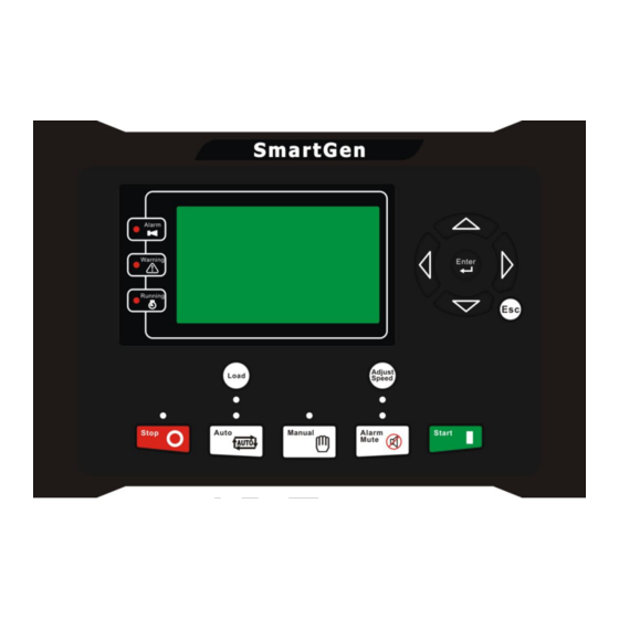
APC715 Pump Unit Controller 4 OPERATION 4.1 INDICATOR LIGHT Note: Selected indicators description: Warning indicator and Alarm indicator: Alarm Type Warning Indicator Alarm Indicator Warning Slow flashing Slow flashing Shutdown Alarm Fast flashing Running indicator: illuminated from crank successful to ETS while off during other periods. -
Page 11: Pushbuttons
WARNING: Default password is 00318, user can change it in case of others change the advanced parameters setting. Please clearly remember the password after changing. If you forget it, please contact Smartgen services and send all information in the controller page of “ABOUT” to us. -
Page 12: Lcd Display
APC715 Pump Unit Controller 4.3 LCD DISPLAY 4.3.1 MAIN DISPLAY Main screen is divided into left and right separate viewing areas, use to select a viewing area; the selected area is marked with in its upper left corner. Both viewing areas show pages; use... -
Page 13: User Menu And Parameters Setting Menu
APC715 Pump Unit Controller ★Status, including as below, Engine speed, battery voltage 1, engine status Indicator Status Green Normal status; No alarm Yellow Warning or idle speed alarm occurs. Shutdown alarm occurs. Example: Engine Pump On load Outlet Pressure Manual Mode 1.0MPa 10Bar 145psi... - Page 14 APC715 Pump Unit Controller ★Commissioning On load, off load or custom commissioning can be chosen. Custom commissioning can configure on load or not during commissioning, when to commissioning and select the mode after commissioning (manual mode, auto mode and stop mode).
- Page 15 APC715 Pump Unit Controller > Start Delay Form 2: Use to scroll Return > >Stop Delay Timers settings, to enter settings (form3), >Preheat Delay Engine >Cranking Time Temp. Sensor to return to previous menu. (form >Crank Rest Time OP Sensor >Safety On Time...
-
Page 16: Auto Start/Stop Operation
APC715 Pump Unit Controller > Start Delay Form5: Press to change cursor > Stop Delay 00008 > Preheat Delay position, used >Cranking Time changing cursor value, Confirm >Crank Rest Time > Safety On Time setting (form 4), exit setting (form >... -
Page 17: Manual Start/Stop Operation
APC715 Pump Unit Controller sequence will be terminated, the Fail to Start fault will be displayed on LCD. 5. In case of successful crank attempt, the “Safety On” timer is activated, allowing Low Oil Pressure, High Temperature, Under speed and Charge Alternator Failure inputs to stabilize without triggering the fault. -
Page 18: On-Load Control Process
APC715 Pump Unit Controller When “After Unload Idle” is enabled, the unit is idle running when crank succeed; unit accelerates to high-speed running automatically and take load after press key by manual. With high temperature, low oil pressure and over speed during pump unit running, controller can protect it to stop quickly (please refer to No.2~7 of Auto start... -
Page 19: Adjust Speed Control
APC715 Pump Unit Controller 4.7 ADJUST SPEED CONTROL Users can set the outlet pressure as the rated value simply by adjusting the engine speed. The “Adjust Speed Control” was divided into auto control and manual control. Manual Adjust Speed: Adjust Speed mode is selected by pressing the button;... -
Page 20: Protection
APC715 Pump Unit Controller 5 PROTECTION 5.1 WARNINGS Warnings are not shutdown alarms and do not affect the operation of the genset. Warning does not lead to shutdown, and when warning condition is no longer present, warning alarm will be cleared automatically. Warning types are as follows:... - Page 21 APC715 Pump Unit Controller Type Description initiate a warning alarm. When the controller detects that the oil pressure has Low Oil Pressure fallen below the pre-set value, it will initiate a warning alarm. When the controller detects that the level sensor is open circuit and the action select “Warn”, it will initiate a...
-
Page 22: Shutdown Alarm
APC715 Pump Unit Controller 5.2 SHUTDOWN ALARM When controller detects shutdown alarm, it will send signal to open breaker and stop the unit. Shutdown alarm must be cleared manually and the fault removed to reset the module. Shutdown alarm types are as follows:... - Page 23 APC715 Pump Unit Controller Type Description When the controller detects the sensor value is higher Flexible Sensor than the max. set value, it will initiate a shutdown 1~6 High alarm. Flexible Sensor When the controller detects the sensor value is lower 1~6 Low than the min.
-
Page 24: Trip Shutdown
APC715 Pump Unit Controller 5.3 TRIP SHUTDOWN On initiation of the “trip shutdown” condition the controller will de-energize the load output to remove the load from the unit. Once this has occurred, the controller will start the Cooling delay and allow the engine to cool before shutting down the engine. Trip shutdown alarm must be cleared manually and the fault removed to reset the module. -
Page 25: Connections
APC715 Pump Unit Controller 6 CONNECTIONS APC715 controller back panel is shown below: Description of terminal connections: Cable Function Description Size 2.5mm Connected with negative of starter battery. Connected with positive of starter battery. If 2.5mm wire length is over 30m, better to double wires in parallel. - Page 26 APC715 Pump Unit Controller Cable Function Description Size power supplied Aux. Output 5 1.5mm terminal 2, rated 7A power supplied Aux. Output 6 1.5mm terminal 2, rated 7A Connected with charger starter’s D+ (WL) Charger(D+) 1.0mm terminals. Being hang up If there is no this terminal.
- Page 27 APC715 Pump Unit Controller Cable Function Description Size 120kΩ resistance had been connected to GOV B2+ 0.5mm GOV B+ innerly. GOV B1+ 0.5mm 2-core shielding wire is recommended, its GOV A+ 0.5mm GOV end earthed. ECU CAN L 0.5mm shielding Impedance-120Ω...
-
Page 28: Definition And Range Of Parameters
APC715 Pump Unit Controller 7 DEFINITION AND RANGE OF PARAMETERS 7.1 PARAMETER CONTENTS AND RANGE (TABLE 1) Items Parameter Default Description Timer Setting Time from remote start signal is Start Delay (0-3600)s active to start the pump unit. Time from remote stop signal is... - Page 29 APC715 Pump Unit Controller Items Parameter Default Description choose the corresponding type. Tooth number of the engine, for judging starter separation Flywheel (10-300) conditions and inspecting of engine Teeth speed. See the following Installation Instruction. Offer standard judge Rated Speed (0-6000)RPM 1500 over/under/loading speed.
- Page 30 APC715 Pump Unit Controller Items Parameter Default Description Fail D+(WL) voltage under this value, charge failure alarms. Max. Crank times of crank attempts. Start (1-10) times When reach this number, controller Attempts will send start failure signal. See form 5.
- Page 31 APC715 Pump Unit Controller Items Parameter Default Description Curve Type (0-15) SGX. See form 5. Open Circuit (0-2) 0: Warn; 1: Shutdown; 2: No action Action Shutdown when external sensor temperature is higher than this High Temp. (0~300)º C value. Detecting only after safety Shutdown delay is over.
- Page 32 APC715 Pump Unit Controller Items Parameter Default Description Curve curve when select resistor curve type or current curve type. Flexible Sensor 1~6 Flexible 0: Disable;1: Enable (can be set as Sensor (0-1) temperature/oil pressure/liquid lever Setting sensor) Curve Type Depends on sensor type.
- Page 33 APC715 Pump Unit Controller Items Parameter Default Description value can be set. Warn when external sensor value is lower than this value. The delay Low Warn (0-9000)% value, “warn enable” and return value can be set. Users should set the corresponding...
- Page 34 APC715 Pump Unit Controller Items Parameter Default Description Flexible Input Port 4 Contents User defined. (0-53) Setting See form 3. 0: Closed to active 1: Open to Active Type (0-1) active 0: From safety on 1: From starting Arming (0-3)
- Page 35 APC715 Pump Unit Controller Items Parameter Default Description Contents (0-53) User defined. See form 3. Setting 0: Closed to active 1: Open to Active Type (0-1) active 0: From safety on 1: From starting Arming (0-3) 2: Always 3:Never Active 0: Warn;...
- Page 36 APC715 Pump Unit Controller Items Parameter Default Description Adjust 0: Not Used; 1: Relay Adjust Speed; (0-2) Speed Type 2:GOV Adjust Speed GOV Output (0-1) 0:Disable;1:Enable. Reverse GOV Center (0-10.0) Default central voltage: 0V Voltage SW1 GOV Voltage (0-10.0) Default volt. range: (-2.5~+2.5)V...
-
Page 37: Programmable Output 1-5 (Table 2)
APC715 Pump Unit Controller 7.2 PROGRAMMABLE OUTPUT 1-5 (TABLE 2) Type Description Not Used Custom Period 1 Custom Period 2 Custom Period 3 Custom Period 4 Custom Period 5 Custom Period 6 Details of function description please see the following. - Page 38 APC715 Pump Unit Controller Reserved Control generator to take load or off On-load Output load. Reserved Reserved Reserved Action when genset is starting and Crank Relay disconnect when crank successful. Action when genset is starting and Fuel Relay disconnect when stop is completed.
- Page 39 APC715 Pump Unit Controller will be switchover circularly if multiple crank is needed. Action when pump unit common Common Alarm warning, common shutdown alarm. Common Trip Action when common trip alarm. Common Shutdown Action when common shutdown alarm. Common Fault Idle Alarm Action when fault idle alarm.
- Page 40 APC715 Pump Unit Controller Failed To Start Action when failed start alarm. Failed To Stop Action when failed stop alarm. Under Speed Warn Action when under speed alarm. Under Speed Shutdown Action when under speed shuts down. Over Speed Warn Action when over speed warning.
-
Page 41: Custom Period Output
APC715 Pump Unit Controller Config 6 High Shut Config 6 Low Shut Outlet High Warn Outlet Low Warn Outlet High Shut Outlet Low Shut 178~229 Reserved Stop Mode Action in stop mode. Manual Mode Action in Manual mode. Reserved Auto Mode Action in Auto mode. -
Page 42: Custom Combined Output
APC715 Pump Unit Controller 7.2.2 Custom Combined Output Defined combination output is composed by 3 parts, condition output S1 or S2 and condition output S3. S1 or S2 is TRUE, while S3 is TRUE, Defined combination output is outputting; S1 and S2 are FALSE, or S3 is FALSE, Defined combination output is not outputting. -
Page 43: Defined Contents Of Configurable Input Ports (All Active When Connect To Grand (B-))
APC715 Pump Unit Controller 7.3 DEFINED CONTENTS OF CONFIGURABLE INPUT PORTS (ALL ACTIVE WHEN CONNECT TO GRAND (B-)) Type Description Including following functions, Indication: indicate only, not warning or shutdown. Warning: warn only, not shutdown. Shutdown: alarm and shutdown immediately Users Configured Never: input inactive. - Page 44 APC715 Pump Unit Controller Reserved Controller will reset maintenance time and date as Reset Maintenance default when input is active. Reserved Connect to sensor digital input. Aux. High Temp Aux. Low OP Connect to sensor digital input. In Auto mode, when the input is active, pump unit...
-
Page 45: Selection Of Sensors
APC715 Pump Unit Controller 7.4 SELECTION OF SENSORS Description Remark 0 Not used 1 Custom Res Curve 2 Custom 4-20mA curve 3 VDO 4 CURTIS Defined resistance’s Temperature 5 VOLVO-EC range (0~6)KΩ, Sensor 6 DATCON default is SGX sensor. 7 SGX... -
Page 46: Conditions Of Crank Dinsconnect Selection
APC715 Pump Unit Controller 7.5 CONDITIONS OF CRANK DINSCONNECT SELECTION Setting description Oil pressure Engine Speed Oil pressure + Engine Speed NOTE: 1. There are 3 conditions to make starter disconnected with engine. Engine speed and oil pressure both can be used separately. We recommend that oil pressure should be using with engine speed together, in order to make the starter motor is separated with engine immediately and can check crank disconnect exactly. -
Page 47: Parameters Setting
APC715 Pump Unit Controller 8 PARAMETERS SETTING 1. Please change the controller parameters when generator is in standby mode only (e. g. Crank disconnect conditions selection, digital input, digital output, various delay), otherwise, shutdown and other abnormal conditions may occurs. -
Page 48: Sensor Select
APC715 Pump Unit Controller 9 SENSOR SELECT 1) When reselect sensors, the sensor curve will be transferred into the standard value. For example, if temperature sensor is SGX (120° C resistor type), its sensor curve is SGX (120° C resistor type); if select the SGD (120°C resistor type), the temperature sensor curve is SGD curve. -
Page 49: Typical Application
APC715 Pump Unit Controller 10 TYPICAL APPLICATION APC715 Pump Unit Controller ISSUE 2013-08-28 Version 1.0 Page 49 of 62... -
Page 50: Installation
Controller is panel built-in design; it is fixed by clips when installed. 1) Battery Voltage Input NOTE: APC715 controller can suit for widely range of battery voltage DC(8~35)V. Negative of battery must be connected with the engine shell soundly. The diameter of wire which from power supply to battery must be over 2.5mm . -
Page 51: Connections Of Controller With J1939 Engine
APC715 Pump Unit Controller 12 CONNECTIONS OF CONTROLLER WITH J1939 ENGINE 12.1 CUMMINS ISB/ISBE Terminals of controller Connector B Remark Fuel relay output Connect with starter coil Start relay output directly Expand 30A relay, battery ECU power Auxiliary output port Set Auxiliary output 1 as “ECU... -
Page 52: Cummins Qsm11(Import)
APC715 Pump Unit Controller 12.3 CUMMINS QSM11(IMPORT) It is suitable for CM570 engine control module. Engine type is QSM11 G1, QSM11 G2. Terminals of controller C1 connector Remark Outside expand relay, when Fuel relay output 5&8 fuel output, making port 5 and... -
Page 53: Cummins Gcs-Modbus
APC715 Pump Unit Controller 12.5 CUMMINS GCS-MODBUS It is suitable for GCS engine control module. Use RS485-MODBUS to read information of engine. Engine types are QSX15, QST30, QSK23 / 45/60/78 and so on. Terminals of controller D-SUB connector 06 Remark... -
Page 54: Cummins Qsz13
APC715 Pump Unit Controller 12.7 CUMMINS QSZ13 Terminals of controller OEM connector of engine Remark Fuel relay output Start relay output Connect to starter coil directly Programmable output 16&41 Setting to idle speed control, normally open output. Making connect during high-speed running of controller via external expansion relay. -
Page 55: Deutz Emr2
APC715 Pump Unit Controller 12.9 DEUTZ EMR2 Terminals of controller F connector Remark Expand 30A relay, battery Fuel relay output voltage of 14 is supplied by relay. Fuse is 16A. Start relay output Connect to starter coil directly Connect to battery negative pole... -
Page 56: Mtu Adec(Sam Module)
APC715 Pump Unit Controller 12.12 MTU ADEC(SMART MODULE) It is suitable for MTU engine with ADEC (ECU8) and SMART module. Terminals of controller ADEC (X1port) Remark Fuel relay output X1 10 X1 Terminal 9 Connected to negative of battery Start relay output... -
Page 57: Perkins
APC715 Pump Unit Controller 12.14 PERKINS It is suitable for ADEM3/ ADEM4 engine control module. Engine type is 2306, 2506, 1106, and 2806. Terminals of controller Connector Remark Fuel relay output 1,10,15,33,34 Start relay output Connect to starter coil directly... -
Page 58: Volvo Edc3
APC715 Pump Unit Controller 12.16 VOLVO EDC3 Suitable engine control mode is TAD1240, TAD1241, and TAD1242. Terminals of controller “Stand alone” connector Remark Fuel relay output Start relay output ECU power supply Programmable output Set programmable output 1 as "ECU power"... -
Page 59: Volvo-Ems2
APC715 Pump Unit Controller 12.18 VOLVO-EMS2 Volvo Engine types are TAD734, TAD940, TAD941, TAD1640, TAD1641, and TAD1642. Terminals of controller Engine’s CAN port Remark ECU stop Programmable output Set programmable output 1 as “ECU stop” ECU power Programmable output Set programmable output 2 as “ECU power”... -
Page 60: Weichai
1.34 Impedance line is recommended. Engine type: GTSC1 NOTE: If there is any question about connection between controller and ECU communication, please feel free to contact Smartgen’s service. APC715 Pump Unit Controller ISSUE 2013-08-28 Version 1.0 Page 60 of 62... - Page 61 APC715 Pump Unit Controller 13 USB Users can set the controller’s parameters and monitor the controller’s status via USB port using the test software which provided by Smatgen company. USB port is active in stop mode only while at other times it couldn’t be detected by PC.
-
Page 62: Fault Finding
APC715 Pump Unit Controller 14 FAULT FINDING Symptoms Possible Solutions Check starting batteries; Controller no response with Check controller connection wirings; power. Check DC fuse. Check the water/cylinder temperature is too high or Genset shutdown not; Check DC fuse. Check emergence stop button is correct or not;...
Need help?
Do you have a question about the APC715 and is the answer not in the manual?
Questions and answers