
Related Manuals for Smartgen HGM6100N-RM


Summary of Contents for Smartgen HGM6100N-RM
- Page 1 HGM6100N-RM REMOTE CONTROL MODULE USER MANUAL SMARTGEN (ZHENGZHOU) TECHNOLOGY CO., LTD.
-
Page 2: Table Of Contents
HGM6100N-RM REMOTE MONITORING MODULE USER MANUAL CONTENT OVERVIEW ..........................4 PERFORMANCE AND CHARACTERISTICS ................5 SPECIFICATION ........................6 OPERATION ..........................7 4.1 KEY DSCRIPTIONS ......................7 4.2 CONTROLLER PANEL ......................8 4.3 REMOTE CONTROL MODE OPERATION ................9 CONNECTIONS ........................10 TYPICAL APPLICATION ...................... - Page 3 Smartgen Technology at the address above. Any reference to trademarked product names used within this publication is owned by their respective companies. SmartGen Technology reserves the right to change the contents of this document without prior notice. Table 1 Software Version...
-
Page 4: Overview
HGM6100N-RM REMOTE MONITORING MODULE USER MANUAL 1 OVERVIEW HGM6100N-RM is remote monitoring module designed for HGM6100N series genset controllers. With RS485 port it can realize functions of remote start/stop, data measuring, and alarm display etc. it is applicable for single remote monitoring system. It can be in the monitoring mode, realizing only monitoring, not controlling, or it can be changed over to remote control mode by local module transfer, monitored and controlled remotely. -
Page 5: Performance And Characteristics
FLASH memory, so that the parameters won't be lost in case of power outage. All parameters can be set from the front panel, but also can be adjusted by RS485 interface via PC. All parameters of HGM6100N-RM must be configured as same as that of local module of HGM6100N controller;... -
Page 6: Specification
HGM6100N-RM REMOTE MONITORING MODULE USER MANUAL 3 SPECIFICATION Table 2 Technical Parameters Items Contents Working Voltage DC8.0V to DC35.0V, continuous <3W(Standby mode: ≤2W) Power Consumption Overall Dimensions 209 mm x 166 mm x 45mm Panel Cutout 186mm x 141mm Working Condition Temperature: (-25~+70)º... -
Page 7: Operation
HGM6100N-RM REMOTE MONITORING MODULE USER MANUAL 4 OPERATION 4.1 KEY DSCRIPTIONS Table 3 Key Descriptions Icon Keys Description Under manual/auto mode, it can stop the running genset. In the state of genset alarm, it can reset the shutdown alarms. Stop/ Reset Under stop mode, press for over 3s, it can test whether panel indicators are normal (lamp test);... -
Page 8: Controller Panel
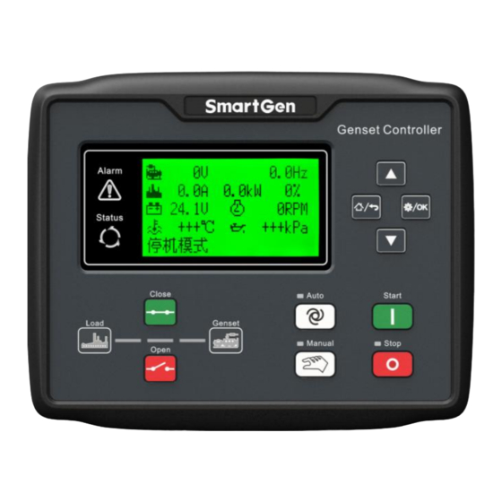
HGM6100N-RM REMOTE MONITORING MODULE USER MANUAL 4.2 CONTROLLER PANEL Fig. 1 HGM6110N-RM Front Panel Indicators Fig. 2 HGM6120N-RM Front Panel Indicators NOTE: Parts of Indicators Descriptions: Alarm Indicator: slowly flashes for warning alarms; quickly flashes for shutdown alarms; light off for none alarms;... -
Page 9: Remote Control Mode Operation
HGM6100N-RM REMOTE MONITORING MODULE USER MANUAL 4.3 REMOTE CONTROL MODE OPERATION When remote control mode input is active on local module, the 4th line of LCD displays remote mode on both remote module and local module, which means remote control mode is active. -
Page 10: Connections
HGM6100N-RM REMOTE MONITORING MODULE USER MANUAL 5 CONNECTIONS HGM6100N-RM lacks a mains voltage 3-phase input terminal comparing with HGM6120N-RM. HGM6120N-RM back panel is as below. Fig. 3 Controller Back Panel Table 4 Wiring Terminal Connection Descriptions Function Cable Size Description DC input B- 2.5mm... - Page 11 CAN H 0.5mm NULL NOTE: Back panel USB is parameter programming port, and controller can be configured via PC. NOTE: Configured parameters of HGM6100N-RM shall be in accordance with that in the monitored HGM6100N controller. HGM6100N-RM Remote Monitoring Module 2019-08-06 Version 1.0...
-
Page 12: Typical Application
HGM6100N-RM REMOTE MONITORING MODULE USER MANUAL 6 TYPICAL APPLICATION Fig. 4 HGM6100N-RM and HGM6100N/CAN Typical Application Diagram HGM6100N-RM Remote Monitoring Module 2019-08-06 Version 1.0 Page 12 of 14... -
Page 13: Installation
7.2 OVERALL DIMENSION AND PANEL CUTOUT Fig. 5 Case Dimensions and Cutout HGM6100N-RM controller can be applicable for (8~35) V DC battery voltage environment. Battery negative must be reliably connected to engine shell. The connection wire between controller power and battery negative and positive should not be less than 2.5mm . -
Page 14: Troubleshooting
HGM6100N-RM REMOTE MONITORING MODULE USER MANUAL 8 TROUBLESHOOTING Table 5 Troubleshooting Symptom Measures No response with power on Check starter battery; Check controller wire connections; Check DC fuse. Abnormal communication of controller Check whether RS485 A and B are connected reversely;...
Need help?
Do you have a question about the HGM6100N-RM and is the answer not in the manual?
Questions and answers