
Related Manuals for Smartgen CMM366A-ET


Summary of Contents for Smartgen CMM366A-ET
- Page 1 CMM366A-ET CLOUD MONITORING COMMUNICATION MODULE USER MANUAL SMARTGEN (ZHENGZHOU) TECHNOLOGY CO., LTD.
- Page 2 SmartGen Technology at the address above. Any reference to trademarked product names used within this publication is owned by their respective companies. SmartGen Technology reserves the right to change the contents of this document without prior notice. Table 1 - Software Version Date...
-
Page 3: Table Of Contents
CMM366A-ET Cloud Monitoring Communication Module User Manual CONTENT OVERVIEW ............................4 PERFORMANCE AND CHARACTERISTICS ..................4 SPECIFICATION ..........................5 PANEL AND TERMINAL DESCRIPTION................... 6 PANEL INDICATOR AND BUTTONS ....................6 ETHERNET ............................7 RS485 ..............................7 RS232 ..............................7 LINK ..............................8 USB HOST ............................ -
Page 4: Overview
APP (IOS or Android) and pc terminal devices. CMM366A-ET module not only can achieve genset monitoring but also can insert some digital alarm input/output signal to achieve monitoring of generator room entrance guard, guard against theft and fire facilities. -
Page 5: Specification
CMM366A-ET Cloud Monitoring Communication Module User Manual SPECIFICATION Table 2 – Technical Data Items Contents Operating Voltage DC 8.0V~35.0V, continuous power supply. Standby: ≤2W Power Consumption Working: ≤5W Digital Input Volt free digital Input Relay Output 1A DC30V Volts free output... -
Page 6: Panel And Terminal Description
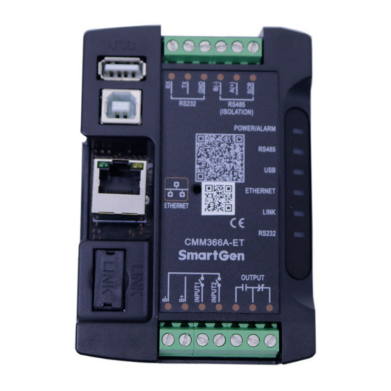
CMM366A-ET Cloud Monitoring Communication Module User Manual PANEL AND TERMINAL DESCRIPTION PANEL INDICATOR AND BUTTONS Fig.1 - CMM366A-ET Front Panel Diagram Table 3 – Indicators Description Icon Note GreenLED Light: Power supply normal indicator POWER/ALARM RedLED Light: Common alarm indicator... -
Page 7: Ethernet
CMM366A-ET Cloud Monitoring Communication Module User Manual ETHERNET CMM366A-ET EHTERNET port is automated negotiation 10/100Mbps working mode, which adopts one to one cross-over cable connect with router as follows, Fig.2 – ETHERNET Connet With Router RS485 Receive genset data information by connecting module RS485 port with Genset Controller RS485 port. -
Page 8: Link
Controller USB port via USB cable. Fig.6 - USB Host Connection USB DEVICE All the parameters can be configured and view CMM366A-ET ID&Login password by connecting USB port with USB disk of PC software. Fig.7 – USB Connect PC Device... -
Page 9: Terminal
CMM366A-ET Cloud Monitoring Communication Module User Manual TERMINAL Table 4 – Terminals Description Function Cable Size Note 1.0mm Connected with negative of starter battery. Connected with positive of starter battery. 3A fuse 1.0mm is recommended. Digital Input 1 1.0mm Active when connect to B-. -
Page 10: Programmable Parameters
CMM366A-ET Cloud Monitoring Communication Module User Manual PROGRAMMABLE PARAMETERS CONTENTS AND SCOPES OF PARAMETERS Table 5 – Parameter Content & Scope Items Parameters Defaults Description Disabled Enabled, DHCP Enable (0-1) obtain IP automatically IP Address (0-255) 192.168.0.101 All changes of Ethernet (e.g. IP... - Page 11 CMM366A-ET Cloud Monitoring Communication Module User Manual baud rate, and communication ID need to be set on the (www.smartgencloud.com) platform, and monitoring module need to reboot after all parameters been set. Table 6 – Digital Input Ports Content Item Description Not Used Not used.
-
Page 12: Pc Configuration Interface
CMM366A-ET Cloud Monitoring Communication Module User Manual PC CONFIGURATION INTERFACE Connecting the USB port of CMM366A-ET communication module with PC USB port to configure the parameters. Fig.8 - IP Configuration Through pressing “ping” key to test whether IP address is correct or not. -
Page 13: System Diagram
CMM366A-ET Cloud Monitoring Communication Module User Manual SYSTEM DIAGRAM One CMM366A-ET module connects with one genset monitor module. It can be connected via RS485 port, LINK port, RS232 port or USB port. Fig.11 - CMM366A-ET System Diagram CMM366-ET Cloud Monitoring Communication Module 2017-12-21 Version 1.0... -
Page 14: Case Dimension And Installation
CMM366A-ET Cloud Monitoring Communication Module User Manual CASE DIMENSION AND INSTALLATION 2 ways for installation: 35mm guide rail in box or screw (M4) installation as below: Fig.12 - CMM366A-ET Case Dimension Fig.13 - CMM366A-ET Guide Rail Installation Fig.14 - CMM366A-ET Screw Installation... -
Page 15: Troubleshooting
CMM366A-ET Cloud Monitoring Communication Module User Manual TROUBLESHOOTING Table 8 – Fault Finding Symptoms Possible Solutions Controller no response with Check power voltage; power. Check controller connection wirings. Check Ethernet setting correct or not; Check whether Ethernet socket indicator is blink or not;...
Need help?
Do you have a question about the CMM366A-ET and is the answer not in the manual?
Questions and answers