
Related Manuals for Smartgen HGM6100NC-RM


Summary of Contents for Smartgen HGM6100NC-RM
- Page 1 HGM6100NC-RM REMOTE CONTROL MODULE USER MANUAL SMARTGEN (ZHENGZHOU) TECHNOLOGY CO., LTD.
- Page 2 Smartgen Technology at the address above. Any reference to trademarked product names used within this publication is owned by their respective companies. SmartGen Technology reserves the right to change the contents of this document without prior notice. Table 1 Software Version...
-
Page 3: Table Of Contents
4.3 REMOTE CONTROL MODE OPERATION ................... 9 5 CONNECTIONS ..........................10 6 TYPICAL APPLICATION ........................12 7 INSTALLATION ..........................13 7.1 FIXING CLIPS ..........................13 7.2 OVERALL DIMENSION AND PANEL CUTOUT .................13 8 TROUBLESHOOTING .........................14 HGM6100NC-RM Remote Monitoring Module User Manual Page 3 of 14... -
Page 4: Overview
1 OVERVIEW HGM6100NC-RM is remote monitoring module designed for HGM6100NC series genset controllers. With RS485 port it can realize functions of remote start/stop, data measuring, and alarm display etc. It is applicable for single remote monitoring system. It can be in the monitoring mode, realizing only monitoring, not controlling, or it can be changed over to remote control mode by local module transfer, monitored and controlled remotely. -
Page 5: Performance And Characteristics
FLASH memory, so that the parameters won't be lost in case of power outage. All parameters can be set from the front panel, but also can be adjusted by RS485 interface via PC. All parameters of HGM6100NC-RM must be configured as same as that of local module of HGM6100NC controller;... -
Page 6: Specification
Protection Level Front panel IP55 Apply AC2.2kV voltage between high voltage terminal and Insulation Intensity low voltage terminal and the leakage current is not more than 3mA within 1min. Weight 0.56kg HGM6100NC-RM Remote Monitoring Module User Manual Page 6 of 14... -
Page 7: Operation
In parameter setting menu press it to exit from parameter settings. NOTE: if remote mode is active, all keys on the panel are functional; if not, only keys are functional on the panel. HGM6100NC-RM Remote Monitoring Module User Manual Page 7 of 14... -
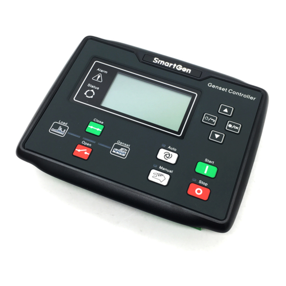
Page 8: Controller Panel
Alarm Indicator: slowly flashes for warning alarms; quickly flashes for shutdown alarms; light off for none alarms; Status Indicator: Light off for standby status genset; flashes once in start/stop process; always light on for normal running. HGM6100NC-RM Remote Monitoring Module User Manual Page 8 of 14... -
Page 9: Remote Control Mode Operation
After remote mode is active, genset mode transfer and genset start/stop operations can be conducted. NOTE: if alarms occur in start/stop process, corresponding alarm information will be synchronously displayed on the LCD of HGM6100NC-RM. HGM6100NC-RM Remote Monitoring Module User Manual Page 9 of 14... -
Page 10: Connections
Max. 20A fuse is recommended. Emergency Stop 2.5mm Fuel 1.5mm Crank 1.5mm Aux. Output 1 1.5mm NOTE: HGM6100NC-RM doesn't have the functions. Aux. Output 2 1.5mm Aux. Output 3 2.5 mm HGM6100NC-RM Remote Monitoring Module User Manual Page 10 of 14... - Page 11 0.5mm NULL NOTE: Back panel USB is parameter programming port, and controller can be configured via PC. NOTE: Configured parameters of HGM6100NC-RM shall be in accordance with that in the monitored HGM6100NC controller. HGM6100NC-RM Remote Monitoring Module User Manual Page 11 of 14...
-
Page 12: Typical Application
6 TYPICAL APPLICATION Fig. 4 HGM6100NC-RM and HGM6100NC/CAN Typical Application Diagram HGM6100NC-RM Remote Monitoring Module User Manual Page 12 of 14... -
Page 13: Installation
Unit: mm Fig. 5 Case Dimensions and Cutout HGM6100NC-RM controller can be applicable for DC (8~35)V battery voltage environment. Battery negative must be reliably connected to engine shell. The connection wire between controller power B+ and B-, and battery negative and positive should not be less than 2.5mm . -
Page 14: Troubleshooting
Check controller wire connections; Check DC fuse. Check whether RS485 A and B are connected reversely; Abnormal communication of controller Adding 120Ω resistance is recommended between RS485 A and B. ______________________________________ HGM6100NC-RM Remote Monitoring Module User Manual Page 14 of 14...
Need help?
Do you have a question about the HGM6100NC-RM and is the answer not in the manual?
Questions and answers