
Subscribe to Our Youtube Channel
Related Manuals for Smartgen CMM366A-4G


Summary of Contents for Smartgen CMM366A-4G
- Page 1 CMM366A-4G CLOUD MONITORING COMMUNICATION MODULE USER MANUAL SMARTGEN (ZHENGZHOU) TECHNOLOGY CO., LTD.
- Page 2 SmartGen Technology at the address above. Any reference to trademarked product names used within this publication is owned by their respective companies. SmartGen Technology reserves the right to change the contents of this document without prior notice. Table 1 - Software Version Date...
-
Page 3: Table Of Contents
CMM366A-4G Cloud Monitoring Communication Module User Manual CONTENT OVERVIEW ............................4 PERFORMANCE AND CHARACTERISTICS ................... 4 SPECIFICATION ..........................5 PANEL AND TERMINAL DESCRIPTION ..................6 PANEL INDICATOR AND BUTTONS ......................6 GPRS ................................7 GPS ................................... 7 SIM INSTALLATION ............................7 RS485 ................................ -
Page 4: Overview
APP (IOS or Android) and pc terminal devices. CMM366A-4G module not only can achieve genset monitoring but also can insert some digital alarm input/output signal to achieve monitoring of generator room entrance guard, guard against theft and fire facilities. -
Page 5: Specification
CMM366A-4G Cloud Monitoring Communication Module User Manual SPECIFICATION Table 2 – Technical Data Items Contents Operating Voltage DC 8.0V~35.0V, continuous power supply. Standby: ≤2W Power Consumption Working: ≤5W Digital Input Digital Input, connect (B-) is active. Relay Output 1A DC30V Volts free output... -
Page 6: Panel And Terminal Description
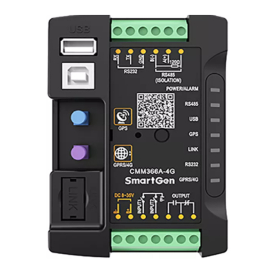
CMM366A-4G Cloud Monitoring Communication Module User Manual PANEL AND TERMINAL DESCRIPTION PANEL INDICATOR AND BUTTONS Fig.1 – CMM366A-4G Front Panel Diagram Table 3 – Indicators Description Icon Note GreenLED Light: Power supply normal indicator; POWER/ALARM RedLED Light: Common alarm indicator. -
Page 7: Gprs
NOTE: GPRS antenna and GPS antenna cannot be connected reversely. SIM INSTALLATION Insert 4G, 3G or 2G SIM card. CMM366A-4G will connect to servers via wireless mobile network. NOTE: 4G GPRS wireless network is supported. Use standard SIM card (25mmX15mm); GPS indicator and GPRS indicator blink in the same time, which means SIM card hasn’t been inserted or bad contacts. -
Page 8: Link
CMM366A-4G Cloud Monitoring Communication Module User Manual RS485 Receive genset data information by connecting module RS485 port with Genset Controller RS485 port. If communication is abnormal, 120Ω terminal resistance is recommonded. One end of shield wire hangs in the air and the other one connects with SCR. -
Page 9: Usb Host
Controller USB port via USB cable. Fig.7 - USB HOST Connection USB DEVICE All the parameters can be configured and view CMM366A-4G ID&Login password by connecting USB port with USB disk of PC software. Fig.8 – USB Connect PC Device... -
Page 10: 4.10 Terminal
CMM366A-4G Cloud Monitoring Communication Module User Manual 4.10 TERMINAL Table 4 – Terminals Description Function Cable Size Note 1.0mm Connected with negative of starter battery. Connected with positive of starter battery. 3A fuse 1.0mm is recommended. Digital Input 1 1.0mm Active when connect to B-. -
Page 11: Programmable Parameters
CMM366A-4G Cloud Monitoring Communication Module User Manual PROGRAMMABLE PARAMETERS CONTENTS AND SCOPES OF PARAMETERS Table 5 – Parameter Content & Scope Items Parameters Defaults Description Gateway 20 Chinese characters, letters or Site Name (0-65535) numbers (0-65535) www.monitoryun.com 40 characters Server Port... -
Page 12: Pc Configuration Interface
Reserved Reserved Reserved Reserved Reserved PC CONFIGURATION INTERFACE Connecting the USB port of CMM366A-4G communication module with PC USB port to configure the parameters. Fig.9 - Gateway Configuration CMM366-4G Cloud Monitoring Communication Module 2017-12-25 Version 1.0 Page 12 of 16... - Page 13 CMM366A-4G Cloud Monitoring Communication Module User Manual Fig.10 - Module Monitoring Interface CMM366-4G Cloud Monitoring Communication Module 2017-12-25 Version 1.0 Page 13 of 16...
-
Page 14: System Diagram
CMM366A-4G Cloud Monitoring Communication Module User Manual SYSTEM DIAGRAM One CMM366A-4G module connects with one genset monitor module. It can be connected via RS485 port, LINK port, RS232 port or USB port. Fig.11 - CMM366A-4G System Diagram CMM366-4G Cloud Monitoring Communication Module 2017-12-25 Version 1.0... -
Page 15: Case Dimension And Installation
CMM366A-4G Cloud Monitoring Communication Module User Manual CASE DIMENSION AND INSTALLATION 2 ways for installation: 35mm guide rail in box or screw (M4) installation as below: Fig.12 - CMM366A-4G Case Dimension Fig.13 - CMM366A-4G Guide Rail Installation Fig.14 - CMM366A-4G Screw Installation... -
Page 16: Fault Finding
CMM366A-4G Cloud Monitoring Communication Module User Manual FAULT FINDING Table 8 – Fault Finding Symptoms Possible Solutions Controller no response with Check power voltage; power. Check controller connection wirings. Check SIM card is inserted or not; GPRS/4G Indicator Not Light Check GPRS antenna is connected or not.
Need help?
Do you have a question about the CMM366A-4G and is the answer not in the manual?
Questions and answers