
Related Manuals for Smartgen CMM366-4G


Summary of Contents for Smartgen CMM366-4G
- Page 1 CMM366-4G CLOUD MONITORING COMMUNICATION MODULE USER MANUAL SMARTGEN (ZHENGZHOU) TECHNOLOGY CO., LTD.
- Page 2 Smartgen Technology at the address above. Any reference to trademarked product names used within this publication is owned by their respective companies. SmartGen Technology reserves the right to change the contents of this document without prior notice. Software Version Date...
-
Page 3: Table Of Contents
CMM366-4G Cloud Monitoring Communication Module User Manual CONTENT OVERVIEW ............................4 PERFORMANCE AND CHARACTERISTICS ................... 4 SPECIFICATION ..........................5 PANEL AND TERMINAL DESCRIPTION ..................6 PANEL INDICATOR AND BUTTONS ..................6 GPRS ............................7 GPS ............................7 SIM INSTALLATION ........................7 RS485 ............................ -
Page 4: Overview
CMM366-34 Cloud Monitoring Communication Module User Manual OVERVIEW CMM366-4G Cloud Monitoring Communication Module is 4G (fits all kinds of networks) wireless network communication protocol switch module, which can achieve gen-set (with SCI) connect to Internet. The module gains gen-set data via RS485 port, USB port, LINK port or RS232 port of gen-set controller modules of international first-class brands including SmartGen, DeepSea, ComAp, etc. -
Page 5: Specification
Standard SMA port (female), SMA port (male) for antenna, active antenna. LTE-TDD/LTE-FDD/HSPA+/TD-SCDMA/EVDO Wireless Network GSM/GPRS/EDGE Case Dimensions 73mmx105mmx33mm Working Conditions Temperature: (-25~+70)°C Humidity: (20~93)%RH Storage Condition Temperature: (-25~+70)°C Weight 0.15kg CMM366-4G Cloud Monitoring Communication Module 2017-09-01 Version 1.0 Page 5 of 20... -
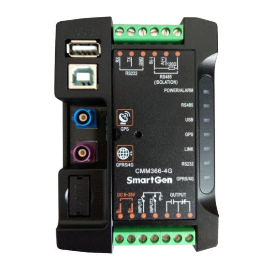
Page 6: Panel And Terminal Description
Blink: Communication normal Normally Extinguish: RS232 disabled RS232(Red) Normally Light: Communication fail Blink: Communication normal Extinguish: CMM366-4G login with server unsuccessfully GPRS/4G(Red) Light: Login with server successfully Blink: Real-time communication normal Lamp test/Rest: Press this button for 1s, all the LEDs are illuminated; hold and press for 10s, reset the module to default and all the LEDs blink for 3 times. -
Page 7: Gprs
NOTE: GPRS antenna and GPS antenna cannot be connected reversely. SIM INSTALLATION Insert 4G, 3G or 2G SIM card. CMM366-4G will connect to servers via wireless mobile network. NOTE: All 4G wireless networks are supported. Use standard SIM card (25mmX15mm); if GPS indicator and GPRS indicator blink in the same time, which means SIM card hasn’t been inserted or bad contacts. -
Page 8: Link
Receive genset data information by CMM366 RS232 port connecting with Gen-set Controller RS232 port. LINK Receive genset data information by CMM366 LINK port connecting with Gen-set Controller LINK port. CMM366-4G Cloud Monitoring Communication Module 2017-09-01 Version 1.0 Page 8 of 20... -
Page 9: Usb Host
Receive genset data information by CMM366 A-type USB mother port connecting with Genset Controller USB port. USB DEVICE Set up all the parameters and view CMM366-4G ID&Login password by CMM366 USB port connecting with PC USB disk port. CMM366-4G Cloud Monitoring Communication Module 2017-09-01 Version 1.0... -
Page 10: 4.10 Terminal
If 120Ω is used, please short connect A (+) with RS485 A(+) 0.5mm 120 Ω, shielding wire single end grounded. 120Ω 0.5mm RS232 RX 0.5mm RS232 TX 0.5mm RS232 RS232 GND 0.5mm CMM366-4G Cloud Monitoring Communication Module 2017-09-01 Version 1.0 Page 10 of 20... -
Page 11: Programmable Parameters
2: 115200 bit/s 0: Manual input location info Location Information (0-1) 1: Use GPS to gain location Longitude (-180-180)° 0.000000 Manually set module location and Latitude (-90-90)° 0.000000 elevation. CMM366-4G Cloud Monitoring Communication Module 2017-09-01 Version 1.0 Page 11 of 20... - Page 12 Digital Input Digital Input 1 Options (0-9) Default: Not used 0:Close to activate Activate Type (0-1) 1:Open to activate See: Form2 Delay (0-20.0) Action delay CMM366-4G Cloud Monitoring Communication Module 2017-09-01 Version 1.0 Page 12 of 20...
- Page 13 Common Alarm Output when there is an alarm. Send remote control commands via cloud platform with fixed Remote Control Output output delay 20s. Reserved Reserved Reserved Reserved Reserved CMM366-4G Cloud Monitoring Communication Module 2017-09-01 Version 1.0 Page 13 of 20...
- Page 14 Single-unit self-starting module DSE7220 AMF module DSE7310 Single-unit self-starting module DeepSea DSE7320 AMF module DSE7410 Single-unit self-starting module DSE7420 AMF module DSE7450 Single-unit self-starting module DSE8610 Single-single parallel module CMM366-4G Cloud Monitoring Communication Module 2017-09-01 Version 1.0 Page 14 of 20...
-
Page 15: Pc Configuration Interface
AMF module GU320A Single-unit self-starting module GU320B Single-unit self-starting module PC CONFIGURATION INTERFACE The USB port of CMM366-4G communication module connects PC port to configure the parameters. Gateway Configuration Cloud Server Configuration CMM366-4G Cloud Monitoring Communication Module 2017-09-01 Version 1.0... - Page 16 CMM366-34 Cloud Monitoring Communication Module User Manual Module Monitoring Interface CMM366-4G Cloud Monitoring Communication Module 2017-09-01 Version 1.0 Page 16 of 20...
-
Page 17: Sms Function And Remote Control
SMS SHORT MESSAGE ALARM When controller detects alarm, it will send short message to phone automatically. NOTE: SMS short message alarm function only suit for SmartGen HGM7000 series and HGM9000 series controllers. NOTE: All alarms about shutdown, trip and stop and trip alarms will be sent to the pre-set phone. Warnings are sent to the phone according to the pre-set. -
Page 18: System Diagram
SYSTEM DIAGRAM One CMM366-4G module connects with one gen-set monitor module. It can be connected via RS485 port, LINK port, RS232 port or USB port. -
Page 19: Case Dimension And Installation
CASE DIMENSION AND INSTALLATION 2 ways for installation: 35mm guide rail in box or screw (M4) installation as below: CMM366-4G Case Dimension CMM366-4G Guide Rail Installation CMM366-4G Screw Installation CMM366-4G Cloud Monitoring Communication Module 2017-09-01 Version 1.0 Page 19 of 20... -
Page 20: Fault Finding
Check settings of gen-set ID and baud rate are correct or not. Check connections; LINK Communication Check LINK port is enabled or not; Abnormal Check settings of gen-set ID and baud rate are correct or not. _________________________________ CMM366-4G Cloud Monitoring Communication Module 2017-09-01 Version 1.0 Page 20 of 20...
Need help?
Do you have a question about the CMM366-4G and is the answer not in the manual?
Questions and answers
How do I install app for cmm3664g