
Related Manuals for Smartgen CMM366B-4G


Summary of Contents for Smartgen CMM366B-4G
- Page 1 CMM366B-4G/CMM366CAN-4G CLOUD MONITORING COMMUNICATION MODULE USER MANUAL SMARTGEN (ZHENGZHOU) TECHNOLOGY CO., LTD.
- Page 2 SmartGen Technology at the address above. Any reference to trademarked product names used within this publication is owned by their respective companies. SmartGen Technology reserves the right to change the contents of this document without prior notice. Table 1 - Software Version Date...
-
Page 3: Table Of Contents
PC CONFIGURATION INTERFACE ..................12 SYSTEM DIAGRAM.......................... 13 CASE DIMENSION AND INSTALLATION ..................13 APP INSTALLATION STEPS ......................15 FAULT FINDING ..........................18 PACKING LIST ..........................18 APPENDIX (ORDER MODEL) ...................... 19 CMM366B-4G/CAN-4G Cloud Monitoring Communication Module 2020-03-10 Version 1.0 Page 3 of 19... -
Page 4: Overview
Applying standard π-type 35mm guide-rail installation or screw-fixed installation, and the module can be installed in the genset control box; Modular structure design, flame retardant ABS enclosure, light weight, compact structure with easy installation. CMM366B-4G/CAN-4G Cloud Monitoring Communication Module 2020-03-10 Version 1.0 Page 4 of 19... -
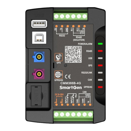
Page 5: Specification
72.5mmx105mmx34mm Working Conditions Temperature: (-25~+70)° C Humidity: (20~93)%RH Storage Condition Temperature: (-30~+80)° C Weight 0.15kg PANEL AND TERMINAL DESCRIPTION PANEL INDICATOR AND BUTTONS Fig. 1 - Panel Indicator CMM366B-4G/CAN-4G Cloud Monitoring Communication Module 2020-03-10 Version 1.0 Page 5 of 19... - Page 6 Press this button for 1s, all the LEDs are illuminated; press for 10s, recover defailt configurations of CMM366B-4G/CMM366CAN-4G and all LEDs flash for 3 times. NOTE: After reset the module, parameters need to be re-configured via PC software or mobile APP. Please operate cautiously. CMM366B-4G/CAN-4G Cloud Monitoring Communication Module 2020-03-10 Version 1.0 Page 6 of 19...
-
Page 7: Gprs/4G Antenna Port
NOTE: GPRS antenna and GPS antenna cannot be connected reversely. SIM INSTALLATION Insert 4G SIM card. CMM366B-4G/CMM366CAN-4G will connect to server via wireless mobile network. NOTE: This module supports 4G wireless network of global network communication. Standard SIM card is applied (size: 25mmx15mm);... -
Page 8: Rs485 Port
Receive genset data information by connecting module RS232 port with Genset Controller RS232 port. Fig. 5 – RS232 Connection LINK PORT Receive genset data information by connecting module LINK port with Genset Controller LINK port. Fig. 6 – LINK Connection CMM366B-4G/CAN-4G Cloud Monitoring Communication Module 2020-03-10 Version 1.0 Page 8 of 19... -
Page 9: Usb Host
USB port via USB cable. Fig. 7 - USB Host Connection USB DEVICE All the parameters can be configured and view CMM366B-4G/CMM366CAN-4G ID&Login password by connecting USB port with PC. Fig. 8 – USB Connect PC Device Fig. 9 - USB Connect SGB100 Module... -
Page 10: Can Port
0.5mm Impedance-120Ω terminal resistor is RS485 A(+) 0.5mm recommended, short connect RS485 A(+) and TR terminal. 0.5mm RS232 RX 0.5mm RS232 TX 0.5mm RS232 port RS232 GND 0.5mm CMM366B-4G/CAN-4G Cloud Monitoring Communication Module 2020-03-10 Version 1.0 Page 10 of 19... -
Page 11: Programmable Parameters
NOTE: Configuration of monitoring genset controller model, communication port, communication baud rate, and communication ID need to be set on the platform, and monitoring module need to restart up after all parameters being set. CMM366B-4G/CAN-4G Cloud Monitoring Communication Module 2020-03-10 Version 1.0 Page 11 of 19... -
Page 12: Pc Configuration Interface
PC CONFIGURATION INTERFACE Connecting the USB port of CMM366B-4G/CMM366CAN-4G communication module with PC to configure the parameters. Fig. 11 - Gateway Configuration Fig. 12 - Module Monitoring Interface CMM366B-4G/CAN-4G Cloud Monitoring Communication Module 2020-03-10 Version 1.0 Page 12 of 19... -
Page 13: System Diagram
CMM366B-4G/CAN-4G Cloud Monitoring Communication Module User Manual SYSTEM DIAGRAM One CMM366B-4G/CMM366CAN-4G module connects with one genset monitor module. It can be connected via RS485 port, LINK port, CAN port, RS232 port or USB port. Fig. 13 - CMM366B-4G/CMM366CAN-4G System Diagram CASE DIMENSION AND INSTALLATION 35mm guide rail installation or screw-fixed (M4) installation can be applied. - Page 14 CMM366B-4G/CAN-4G Cloud Monitoring Communication Module User Manual Fig.15 - CMM366B-4G/CMM366CAN-4G Guide Rail Installation Fig.16 - CMM366B-4G/CMM366CAN-4G Screw Installation CMM366B-4G/CAN-4G Cloud Monitoring Communication Module 2020-03-10 Version 1.0 Page 14 of 19...
-
Page 15: App Installation Steps
Open "tesilayun" APP from the mobile, users have to register for the first time of using it, after register input Account Number and Password to enter APP. Fig. 18 - Add Genset Interface Screenshot CMM366B-4G/CAN-4G Cloud Monitoring Communication Module 2020-03-10 Version 1.0 Page 15 of 19... - Page 16 Modem and add Modem ID, or manually input Modem ID (as Fig. 12's Module ID), choose Modem type, click Confirm, and it is OK as Fig. 18. Fig. 19 - Genset Control Interface CMM366B-4G/CAN-4G Cloud Monitoring Communication Module 2020-03-10 Version 1.0 Page 16 of 19...
- Page 17 Fig. 20, such as controller brand, controller series, controller model, model ID, Communication Port, Baud Rate etc. Click Save after setting. Users can obtain controller genset information by clicking the function icons in Fig. 19. CMM366B-4G/CAN-4G Cloud Monitoring Communication Module 2020-03-10 Version 1.0 Page 17 of 19...
-
Page 18: Fault Finding
Name Quantity Remark CMM366CAN-4G (with CAN port) Cloud Monitoring Module CMM366B-4G (without CAN port) 4G+GPS/BD Two-in-one Antenna Certification User manual SIM Card Tray RS485 Communication Cable Length: 50cm CMM366B-4G/CAN-4G Cloud Monitoring Communication Module 2020-03-10 Version 1.0 Page 18 of 19... -
Page 19: Appendix (Order Model)
CMM366CAN-4G-S04 Europe/Africa/ FDD-LTE:B1/B3/B5/B7/B8/B20 CMM366B-4G-S02 Korea/Thailand/ TDD-LTE:B38/B40/B41 CMM366CAN-4G-S02 Middle East WCDMA:B1/B5/B8 GSM:900/1800MHz South America/ FDD-LTE: Australia/ B1/B2/B3/B4/B5/B7/B8/B28 CMM366B-4G-S03 New Zealand TDD-LTE:B40 CMM366CAN-4G-S03 WCDMA:B1/B2/B5/B8 GSM:850/900/1800/1900MHz CMM366B-4G-S05 Japan FDD-LTE:B1/B3/B8/B18/B19/B26 CMM366CAN-4G-S05 _____________________________________ CMM366B-4G/CAN-4G Cloud Monitoring Communication Module 2020-03-10 Version 1.0 Page 19 of 19...
Need help?
Do you have a question about the CMM366B-4G and is the answer not in the manual?
Questions and answers